US1917536A - Threshing machine - Google Patents
Threshing machine Download PDFInfo
- Publication number
- US1917536A US1917536A US503076A US50307630A US1917536A US 1917536 A US1917536 A US 1917536A US 503076 A US503076 A US 503076A US 50307630 A US50307630 A US 50307630A US 1917536 A US1917536 A US 1917536A
- Authority
- US
- United States
- Prior art keywords
- shaft
- belt
- housing
- conveyor
- grain
- Prior art date
- Legal status (The legal status is an assumption and is not a legal conclusion. Google has not performed a legal analysis and makes no representation as to the accuracy of the status listed.)
- Expired - Lifetime
Links
- 239000010902 straw Substances 0.000 description 16
- 210000003811 finger Anatomy 0.000 description 6
- 238000010276 construction Methods 0.000 description 3
- 239000000463 material Substances 0.000 description 3
- 238000004140 cleaning Methods 0.000 description 2
- 241000507564 Aplanes Species 0.000 description 1
- 101150004141 Vcan gene Proteins 0.000 description 1
- 238000013459 approach Methods 0.000 description 1
- 150000001768 cations Chemical class 0.000 description 1
- 239000002131 composite material Substances 0.000 description 1
- 238000007599 discharging Methods 0.000 description 1
- 239000000428 dust Substances 0.000 description 1
- 238000005507 spraying Methods 0.000 description 1
- 239000002699 waste material Substances 0.000 description 1
Images


Classifications
-
- A—HUMAN NECESSITIES
- A01—AGRICULTURE; FORESTRY; ANIMAL HUSBANDRY; HUNTING; TRAPPING; FISHING
- A01F—PROCESSING OF HARVESTED PRODUCE; HAY OR STRAW PRESSES; DEVICES FOR STORING AGRICULTURAL OR HORTICULTURAL PRODUCE
- A01F12/00—Parts or details of threshing apparatus
- A01F12/56—Driving mechanisms for the threshing parts
Definitions
- This invention aims to provide a threshing
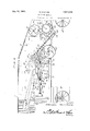
- Figure 1 shows in side elevation, a device constructed in accordancev with the invenf tion, parts being broken away 5 ⁇
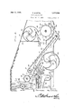
- Figure 2 is a vertical .longitudinal section parts, vbeing broken away;
- FIG. 3 is anenlarged vertical section, parts being broken away; Y v
- Figure 4 is an elevation showing a portionv 3C of -tliejadjusting means for the riddles.
- FIGS. 5 and 6 are showing portions of one of the platforms;V
- Figure 7 is a section taken approximately on the line '7 7 of Figure 1.
- r1 ⁇ he device forming ⁇ the subject matter of this application comprises the usual housing 1, carried on Wheels WV. 1
- rl ⁇ he drives will be tracedout first.
- a rst ci e shaft 2 is mounted for rotation in the housing 1 and is driven in any suitable Way.
- the end of the rst shaft 2Vthere is a pulley 3 Wnicn engages the forward run of a substanleys 5 on a second shaft 6 anden thirdr shaft 7, which are journaled in the housing 1.
- VThe shafts 6 T are located'a littlebehind'the R first shaft'2, the shaft f3' being disposed above the shaft 2, and the shaft 7 being disposed Y and above theA fourthishaft 11.
- rllhe pulley VTithY the above and other objects in View
- the pulley 8 onthe first shaft 2 drives a substantially horizontal belt 12 engaged With a pulley 14@ on a fifth shaftBO journaled for rotation in the housing 1 and located behind 1a drives an upwardlyand rearvvardlyextendedbeltl engaged with a pulleyl onV A a'sixt'h shaft 17 mounted to Vrotate in the housing 1.
- a belt 23 is downwardly and rearwardly extended, and the belt is operated by the pul-v ley 14 on the shaft SOQ
- the belt 23 drives a 75 pulley 24l-on a ninth shaft 25 supported'for ⁇ rotation in the housing ⁇ 1.-'
- the shaft 25 is located behind the shaft 11 and atrifle above the said shaft.
- The' belt 23 drives a pulley 26 on a tenth shaft 27journaled'in the hous- 8G" i v f ing 1 and located behind the shaft 25.5V
- belt 28 is located on the opposite side of the machine from thebelts 15 and and drives aneleventh yshaft 29 supported for rotation r in the upperrear portion of the housing 1.9 a
- the drives require little or no explanation, but it may bestated that the pulley 3 is driven by the shaft 2, the vpulley 3 opera-ting the'belt et, andthe belt l rotating the shafts and 7 Vby Way of the pulleys 5.
- #The belt9 isd'riven by the pulley 8 on the shaft ⁇ 25 and rotates the shaft 11 by Way of the pulleylO.
- the belt 12 I drives the pulley 14 and rotates the shaft 30.A From the shaft 30 rotation is imparted to '95- the belt 15 'and' the belt 15 drivesthe' shafts 17 and 19. rlhe sh 22is driven from the shaft 19 by the belt 20. -The belt 23 drives the shaft .25 by Way of the pulleyV 2li, 'and drives the shaft 27 byway of the pulley26., F rom the shaft 30, rotation is impartedV to l the shaft 29 through the instrumentality of the belt 28.
- the top of the housing 1 is forwardly and downwardly inclined at its forward end, as
- the gate 36 is pivoted at 37, at its forward end., to ⁇ one end of a spiral casing 39 located in the housing 1.
- the casing39 has a rearwardly extended and downwardly inclined outlet 38, and the gate 36 is located above, and forms -the upperwall, of
- a fan blower 4() is located in the casing 39 vand is driven by the shaft 6.
- a cylinder 41 which is operated by the shaft 7.
- the cylinder 41 cooperates with a concave 42 ⁇ fixed in the housing' 1 and located below the cylinder.
- the concave 42 has a straight, long, upwardly inclined rear end 43 to which a gate 44 is pivoted at 45, the gate-44 being under the control of an operator.
- the gate 44 is4 located beneath the rear end of the valve34.
- the concave 42 is placed above .a stepped bottom 46 Vcarried by the housing land leading to a trough47 in which is journaled for rotation, a shaftj48 driven by any common instrumentality (not shown).
- the shaft 48 carries an upwardly and rearwardlyV inclined conveyor belt 49 engaged'with cylindrical pulley 50 on the sixth shaft 17.
- the ,con- Veyor belt 49 passes around an upwardly and rearwardly inclined platform 51 which is imperforate, the platform 51 being supported by the housi g 1.
- a toothed cylinder .or ⁇ picker 52 is carried by the shaft 19.
- a toothed cylinder,53 is carried by the shaft 22.
- the shaftsv 17, 19 and 22 are located' substantially in la common plane, which is upwardly and rearwardly inclined.
- the toothed cylinder 53 is located above the forward end of the straw carrier 54, the straw carrier being operated by the eleventh shaft 29.
- the straw carrier needk not bedescribed in detail because it may be of any common construction well known in the art.
- VAcasing 55 is located in the bottom por* tion of the housing 1, lbeneath the inner end of the belt conveyor 49.
- a ⁇ fan blower 56 is carried by the shaft 11 and operates in the casing 55.
- the fan blower 56 has curved blades 57.
- the fan blower casing' 55 isl supplied with a rearwardly extended, upwardly inclined outlet tube 58.
- Fixed deflectors 59 are carried by the housing 1 and are located behind'the lower wall of the outletA tube 58 of the blower casing 55. The deflectors 59 are upwardly and rearwardly inclined, as shown in Figure 2 of the drawings.
- Dampers 6() are disposed one above the other, andare placed in the outlet 58, above the lower wallof the outlet, and at the rear end of the lower wall of the outlet.
- the dampers 60 are pivotally mounted intermediate the ends, and are under the control of ⁇ an operator, as shown in Figure 4, the shafts of the dampers 60 being marked by the numeral 64, and
- a V-shaped deflector 61 having its apex forwardlydisposed.
- a second deflector 62 is located in ,the outlet tube 58, above the deflector 61.
- the second deflector -62 has a V-shaped, forwardly extended end 63, which projects forwardly, considerably beyond the forward end of the deflector 61.
- a movable deilector 65 At the end of the deflector 62 is a movable deilector 65, which is pivotally mounted which is shown at 66, the deflector 65 being under the control of an operator.
- a forwardly extended, adjustable deilector 67 which is pivotally mounted as shown at.
- a substantially vertical fixed deilector 71 is mounted in the casing 61 at the upper end of the upper wall of 'the outlet tube 58 of the blower casing 55, and extends upwardly between the toothed cylinder 52 andthe pulley 50 which carries the conveyor belt 49.
- a transverse trough 72 is carried by the housing 1 and is located immediately to the rear of the fan casing 55. In the trough 72, there operates a worm conveyor 73, which may be driven bythe shaft 25.
- a stepped, downwardly and forwardlyy inclined chute 74 is carried by the housing land leads to the trough 72 in which the worm conveyor-73 operates.
- second chute board 75 which is stepped and downwardly and forwardly7 inclined, is carried by the housing 1 and extends below the rear end of the chute 74.
- the chute boa-rd 75 leads to a trough 76, die- ⁇ posed transversely of the housing 1.
- worm conveyor 77 l operates in the trough 76 and is operated by the shaft 27.
- a shaft 106 which is located at the' Referring especially to Figures 4, 1 and 7 and are located substantially in a horizonerates a carrier 79 which is a'composite structure.
- carrier 79r is made up ofja rear slide bar 80, a forward slide bar 81, and a link 82 located between the slide bars.
- - Pivot elements 83 and 84 connect the-rear and for-f ward ends of the link 82, respectively, with the forward end of the'slide'bar 80, and with the rear end of the slide bar 81.
- Substantially vertical hangers 85 are connectedatV their upper ends by pivote'le-y ments 86 with the slide bar 80 and the slide bar 81 and by the pivot element 84'with the link 82 and the slide bar 81.
- the silde bar 80 -the link 82 andthe slide bar 81 havea plurality of holes 87l for the pivot elements 86 and 84, the said holes beingplainly marked, so that anroperator need make no mistake in carrying out Vthe adjustments hereinafter described.
- VThe-numeral 88 marks a substantially vertical pendulum, hung at its upper end, as shown at 89, on the casing 1, to swing in a vertical plane, substantially parallel to the line of advance of the machine.
- the pendulum 88 is provided 'intermediate its ends with al plurality of marked holes 90 for the receipt of the pivotfelement 83.
- a Aweight 91 is secured.
- the lower end ofthe rearmost hanger 85 A is'pivoted at 93 tothe rear end of a screen 94disposed above the chute board 75.
- the forward end ofthe screen 94 is pivoted at 95, by means of a shaft or otherwise, to a frame 96 located in the casing 1.
- the intermediate' links 85 are pivoted'through the holes 92, as shown at 111,to the frame' 96.
- the forward links 85 carry, attheir lower forward end of the frame 96.
- a deflector Y 97 is mounted 'on the frame 96 at the forward end of the screen 94, ⁇ and is upwardly vand rearwardly inclined'.V
- An upper screen 98 is carried by the frame 96 and has'rearwardly and upwardly eX- 4 tended fing-ers 99 at 'its rear end.v
- a lower screen 100 is carried by the frame 96, below the screen 98, and is supplied at its rear end with upwardly and rearwardly inclined end of fthe upper screen 98.
- the deliector 102 has a slight rearward and backward inclination, and; is disposed in the path of the ⁇ throat 70.
- Aplatform 108 which ils'stepped,
- the lplatform or defiector 103 is locatedin ,front of the throat 69.
- Theshaft 106. is connected ⁇ to pitmans 107, carrying, each, a strap 108, Jchest-raps 108 being engaged Iaround eccentrics ⁇ 109 on the in Figure 2, the straw. being deposited onthe straw carrier 54.
- Thestraw, of course,l is carried along by the toothedcylinders' 52 and" 53; #Theblast of air' from the fan blower 56, .proceeding through the throat 69,
- the function of the deflector 97 is to direct the air upwardly v through tbe fingers 101 vand v99,v as thev air moves backwardly, above the chute board 7 4.y
- the invention provides means for keeping the straw iight andthoioughly separated, as hereinbefore explained, and as a consequence, less work is thrown on the cleaning means for the grain than is the case with many machines.
- the grain is thoroughly removed from the chaff and straw, before the chaff and straw moves out of the rear end of the machine, and waste of grain is cut
- the position of f down to a minimum.l y'lhemachine islightin construction, owing to the fact that many parts heretofore found necessary may be omitted, andthe 'machine maybe 'drawn or propelled by any suitable-means, over the field, with the expenditure of littleepower.
- the flying grain is checked at various parts of the machine without resorting to power driven devices for that purpose, and the advantages of this feature are obvious to any person skilled y'in the art.
- a housing In a threshing ⁇ machine, a housing, a frame vin the housing, a ,forward screen carriedby the frame, a rear screen having its forward end pivoted tothe frame, means for directing material fromthe forward screen to the rear screen, guides on the housing, a rear slide bar mounted in one of the guides, a forward slide bar mounted in another of the.
Landscapes
- Life Sciences & Earth Sciences (AREA)
- Environmental Sciences (AREA)
- Threshing Machine Elements (AREA)
Description
July l1, 1933.
SQ MCINTIRE THRESHING MACHINE Filed Dec?. 17, 1950 4 Sheets-Sheet ly July M, 1933. s. Mcm-TIRE ],917,536
THRESHING MACHINE Filed Dec. 17. 1930 4 sheets-sheet 2 Filed Deo. '17, 1930 4 Sheets-Sheet 3 SHN/U51.
@Houd m o.
july M, 1933. s. Mcm-MRE THRESHING MACHINE Filed Deo. 17, 1930 4 Sheets-Sheet 4 rasees July 1i,
' santini.' Merriman; or NEWTON, 'Kansas l, tensa."
Parana.
rnansniive Macallan Application'led December 17, 1930. Serial No. 503,076. Y.
This invention aims to provide a threshing."
'5 that it Will be made to 'operate properly Whether going up hill or down hill.
lt is Within the province of the disclosure to improve generally and to enhance the utility of devices of that type to which the inlil vent-ion appertains. i
which Will appear as', the description proceeds7 the invention resides in the combina.- tion and arrangement of pai ts and in the del5 tails of construction hereinafter described and claimed, it being understood that changes in the precise embodiment of the invention herein disclosed, may be made vWithin the scope of what is claimed7 Without departing 20 from the spirit of the invention.
ln the accompanyingdrawings: Figure 1 shows in side elevation, a device constructed in accordancev with the invenf tion, parts being broken away 5` Figure 2 is a vertical .longitudinal section parts, vbeing broken away;
Figure 3 is anenlarged vertical section, parts being broken away; Y v
Figure 4 is an elevation showing a portionv 3C of -tliejadjusting means for the riddles, and
attendant. parts;
Figures' 5 and 6 are showing portions of one of the platforms;V
Figure 7 is a section taken approximately on the line '7 7 of Figure 1.
r1`he device forming` the subject matter of this application comprises the usual housing 1, carried on Wheels WV. 1
rl`he drives will be tracedout first. Referring to Figure 1, it Will be seen that a rst ci e shaft 2 is mounted for rotation in the housing 1 and is driven in any suitable Way. Gn the end of the rst shaft 2Vthere is a pulley 3 Wnicn engages the forward run of a substanleys 5 on a second shaft 6 anden thirdr shaft 7, which are journaled in the housing 1. VThe shafts 6 T are located'a littlebehind'the R first shaft'2, the shaft f3' being disposed above the shaft 2, and the shaft 7 being disposed Y and above theA fourthishaft 11. rllhe pulley VTithY the above and other objects in View,
tially vertical belt e engagedA around pul-` below the shaft 2, the shaft 2 carrying a'pul# ley 8 about whichl is enga-ged a downwardly and rearwardly extended belt), cooperating with the pulley 10 on afourth shaft 11 sup'l ported for rotation in the housing l; 55
The pulley 8 onthe first shaft 2 drives a substantially horizontal belt 12 engaged With a pulley 14@ on a fifth shaftBO journaled for rotation in the housing 1 and located behind 1a drives an upwardlyand rearvvardlyextendedbeltl engaged with a pulleyl onV A a'sixt'h shaft 17 mounted to Vrotate in the housing 1. Y .i Y
'-lhe belt lois engaged with .a pulley 181on a seventh shaft v19 .journaledin the housing 1.k The shaft 19 drives arearwardly and'up- 'Wardly extended belt 2O Which maybe lo# cated on the oppositeside of 'the` machine from the beltl, The belt 20 is engaged 70 around Va pulley 21 onV an eighth shaft 22 supported for rotation in thehou'sing" 1'. y
A belt 23 is downwardly and rearwardly extended, and the belt is operated by the pul-v ley 14 on the shaft SOQ The belt 23 drives a 75 pulley 24l-on a ninth shaft 25 supported'for `rotation in the housing` 1.-' The shaft 25 is located behind the shaft 11 and atrifle above the said shaft. The' belt 23 drives a pulley 26 on a tenth shaft 27journaled'in the hous- 8G" i v f ing 1 and located behind the shaft 25.5V A perspective views,
belt 28 is located on the opposite side of the machine from thebelts 15 and and drives aneleventh yshaft 29 supported for rotation r in the upperrear portion of the housing 1.9 a The drives require little or no explanation, but it may bestated that the pulley 3 is driven by the shaft 2, the vpulley 3 opera-ting the'belt et, andthe belt l rotating the shafts and 7 Vby Way of the pulleys 5. #The belt9 isd'riven by the pulley 8 on the shaft `25 and rotates the shaft 11 by Way of the pulleylO. The belt 12 I drives the pulley 14 and rotates the shaft 30.A From the shaft 30 rotation is imparted to '95- the belt 15 'and' the belt 15 drivesthe' shafts 17 and 19. rlhe sh 22is driven from the shaft 19 by the belt 20. -The belt 23 drives the shaft .25 by Way of the pulleyV 2li, 'and drives the shaft 27 byway of the pulley26., F rom the shaft 30, rotation is impartedV to l the shaft 29 through the instrumentality of the belt 28.
zal
The top of the housing 1 is forwardly and downwardly inclined at its forward end, as
L shown at 31. There are corrugations 32 on 36 which is under the control of an o erator like the valve 34. The gate 36 is pivoted at 37, at its forward end., to `one end of a spiral casing 39 located in the housing 1. The casing39 has a rearwardly extended and downwardly inclined outlet 38, and the gate 36 is located above, and forms -the upperwall, of
l the outlet 38. A fan blower 4() is located in the casing 39 vand is driven by the shaft 6.
Below the outlet 38Vof the fan casing' 39 is disposed a cylinder 41 which is operated by the shaft 7. The cylinder 41 cooperates with a concave 42 `fixed in the housing' 1 and located below the cylinder. The concave 42 has a straight, long, upwardly inclined rear end 43 to which a gate 44 is pivoted at 45, the gate-44 being under the control of an operator. The gate 44 is4 located beneath the rear end of the valve34.
The concave 42 is placed above .a stepped bottom 46 Vcarried by the housing land leading to a trough47 in which is journaled for rotation, a shaftj48 driven by any common instrumentality (not shown). The shaft 48 carries an upwardly and rearwardlyV inclined conveyor belt 49 engaged'with cylindrical pulley 50 on the sixth shaft 17. The ,con- Veyor belt 49 passes around an upwardly and rearwardly inclined platform 51 which is imperforate, the platform 51 being supported by the housi g 1. Y
A toothed cylinder .or `picker 52 is carried by the shaft 19. A toothed cylinder,53 is carried by the shaft 22. The shaftsv 17, 19 and 22 are located' substantially in la common plane, which is upwardly and rearwardly inclined. The toothed cylinder 53 is located above the forward end of the straw carrier 54, the straw carrier being operated by the eleventh shaft 29. The straw carrier needk not bedescribed in detail because it may be of any common construction well known in the art.
VAcasing 55 is located in the bottom por* tion of the housing 1, lbeneath the inner end of the belt conveyor 49. A `fan blower 56 is carried by the shaft 11 and operates in the casing 55. The fan blower 56 has curved blades 57. The fan blower casing' 55 isl supplied with a rearwardly extended, upwardly inclined outlet tube 58. Fixed deflectors 59 are carried by the housing 1 and are located behind'the lower wall of the outletA tube 58 of the blower casing 55. The deflectors 59 are upwardly and rearwardly inclined, as shown in Figure 2 of the drawings. Dampers 6() are disposed one above the other, andare placed in the outlet 58, above the lower wallof the outlet, and at the rear end of the lower wall of the outlet. The dampers 60 are pivotally mounted intermediate the ends, and are under the control of `an operator, as shown in Figure 4, the shafts of the dampers 60 being marked by the numeral 64, and
suitable means (Figure 4) being provided,
whereby the shafts 64 and the dampers 6() may be. governed by anoperator. The showing of Figure 4, at 110, will illustrate how any of the various valves, gates, and dampers, which aresaid'to be under the control of an operator, may be operated.
In the outlet tube 58 of the blower casing 55 is locatedI a V-shaped deflector 61 having its apex forwardlydisposed. A second deflector 62 is located in ,the outlet tube 58, above the deflector 61. The second deflector -62 has a V-shaped, forwardly extended end 63, which projects forwardly, considerably beyond the forward end of the deflector 61. At the end of the deflector 62 is a movable deilector 65, which is pivotally mounted which is shown at 66, the deflector 65 being under the control of an operator. At the apex of the deflector 61 is a forwardly extended, adjustable deilector 67, which is pivotally mounted as shown at. 68, the deflector'67 being under the control of an operator. rlhe top of a seconddefiector 62, and the upper part of the loutlet tube 58 for the blower casing 55 form an upper, reduced throat 69. The lower portion of the second deflector 62, and the upper wall of the first deflector 61 form a lowery throat 70. A substantially vertical fixed deilector 71 is mounted in the casing 61 at the upper end of the upper wall of 'the outlet tube 58 of the blower casing 55, and extends upwardly between the toothed cylinder 52 andthe pulley 50 which carries the conveyor belt 49. l
A transverse trough 72 is carried by the housing 1 and is located immediately to the rear of the fan casing 55. In the trough 72, there operates a worm conveyor 73, which may be driven bythe shaft 25. A stepped, downwardly and forwardlyy inclined chute 74 is carried by the housing land leads to the trough 72 in which the worm conveyor-73 operates. second chute board 75, which is stepped and downwardly and forwardly7 inclined, is carried by the housing 1 and extends below the rear end of the chute 74. The chute boa-rd 75 leads to a trough 76, die-` posed transversely of the housing 1. A
worm conveyor 77 l operates in the trough 76 and is operated by the shaft 27.
, tal line. In each set of guides 78,".there open-ds, a shaft 106, which is located at the' Referring especially to Figures 4, 1 and 7 and are located substantially in a horizonerates a carrier 79 which is a'composite structure. rihe carrier 79r is made up ofja rear slide bar 80, a forward slide bar 81, and a link 82 located between the slide bars.- Pivot elements 83 and 84 connect the-rear and for-f ward ends of the link 82, respectively, with the forward end of the'slide'bar 80, and with the rear end of the slide bar 81. Substantially vertical hangers 85 are connectedatV their upper ends by pivote'le-y ments 86 with the slide bar 80 and the slide bar 81 and by the pivot element 84'with the link 82 and the slide bar 81. The silde bar 80 -the link 82 andthe slide bar 81havea plurality of holes 87l for the pivot elements 86 and 84, the said holes beingplainly marked, so that anroperator need make no mistake in carrying out Vthe adjustments hereinafter described. Y
VThe-numeral 88 marks a substantially vertical pendulum, hung at its upper end, as shown at 89, on the casing 1, to swing in a vertical plane, substantially parallel to the line of advance of the machine. l The pendulum 88 is provided 'intermediate its ends with al plurality of marked holes 90 for the receipt of the pivotfelement 83. vOn the lower' end of the pendulum 88, a Aweight 91 is secured.
- The side walls of the casing 1 are supplied with holes 92 located yon each side of the machine, Vand the structure shown 1n Figure 1 and herembefore described, as respecting thehangers 85, is located at each side of the machine. v
The lower end ofthe rearmost hanger 85 A is'pivoted at 93 tothe rear end of a screen 94disposed above the chute board 75. The forward end ofthe screen 94 is pivoted at 95, by means of a shaft or otherwise, to a frame 96 located in the casing 1. The intermediate' links 85 are pivoted'through the holes 92, as shown at 111,to the frame' 96.
The forward links 85 carry, attheir lower forward end of the frame 96. A deflector Y 97 is mounted 'on the frame 96 at the forward end of the screen 94, `and is upwardly vand rearwardly inclined'.V
An upper screen 98 is carried by the frame 96 and has'rearwardly and upwardly eX- 4 tended fing-ers 99 at 'its rear end.v A lower screen 100 is carried by the frame 96, below the screen 98, and is supplied at its rear end with upwardly and rearwardly inclined end of fthe upper screen 98. The deliector 102 has a slight rearward and backward inclination, and; is disposed in the path of the` throat 70. Aplatform 108, which ils'stepped,
is carried Jbyfthe frame 96 and has vat its rear end, a` beam 104,- carrying rearwardly', ex-V tending fingers 10.5 which project above the deflector 102. V The lplatform or defiector 103 is locatedin ,front of the throat 69.
Theshaft 106.is connected` to pitmans 107, carrying, each, a strap 108, Jchest-raps 108 being engaged Iaround eccentrics` 109 on the in Figure 2, the straw. being deposited onthe straw carrier 54. Thestraw, of course,l is carried along by the toothedcylinders' 52 and" 53; #Theblast of air' from the fan blower 56, .proceeding through the throat 69,
strikes" the deiector 71', and is carried up? wardly, lin front of the toothed cylinder 52,
the straw being thereby spread, opened out, v
and 'distributech as it is carried rearwardly.`
Any grainwhich may fall from the strawat this time, goesdownwardly on the platform 103, and passes through the fingers 105, onl
the Aupper screen 98. At this point itis to roo be noted, that there lis a blast of air through the throat 70 which is directed by the deector 102 against the material on the lingers 105. Y
. '1,05 The grain carried upwardly by the belt 49 is deposited on the platform 103,*and moves through the fingers 10.5, upon the upper lscreen 98. There is a blast of air, also, from the outlet tube 58 of the casing 51, through `the screens 100 and98, under the direction of the -defiectors 59,and smalltrash is carried overwthe fingers 99 Y,and 101upon the screen 94, where the grain receives a'final riddling,
the grain whichpasses through the'screen 94 falling `on the chute-board `75 and being returned to the trough 76, from which it is carried away by the conveyor 77 vThe grain which finds its way on the board 74 is returnedtothe vtrough 72 and is carri-ed away by the worn conveyor 7 3. The function of the deflector 97 is to direct the air upwardly v through tbe fingers 101 vand v99,v as thev air moves backwardly, above the chute board 7 4.y
When the machine moves down hill, ther natural tendency of the screens 98 and 100 is to incline down hill also, and when themachine'V moves up hill, the naturaltendency of `the screens 98 and 100 isvto incline downwardly and -rearwardlyand discharge'the grain and various attachments, heretofore used to handle the straw and chaff are dispensed with.
too fastto the rear. .This tendency is corrected bythe action of the pendulum 88 andthe weight 89. It is obvious, that as the machine is inclined with respect to the horizon-` tal, the pendulum 88 will swing with respect to the vertical, the carriers79 moving in the;
guides 78, and the position of the hangers 85 with respect to the eccentrics lOQ'being changed, andthe motion of the screens l98 and 100 being so altered lthat .if the machine Vis down hill, with its forward end 'lowermost,
the rearward movement of the grain on the" screens 98 and 100 will be enhanced; whereas, if the machine is moving `up hill, with its forward end raisedythe rearward movement of the grain on the screens 98 and 100 will be retarded, and 'thegrai'n-will not moveA rearwardly too fast.
The :function of the pendulum 8S: is to ad.V
just the position ofthe hangers'85 with respect to the operatingl means shown at 109 in Figure 4, and it has been found 'in practice, that thesuccessful operation of the screens 98V and 1,00 `depends more upon the position of the hangers 85 with respect to the operating ries the straw and chaff to thetop'of the maf chine, as shown by the arrows,`thereby keeping the straw thin as it moves'rearwardly,
There, is ample space at the top of thevmachine for the blast of air to carry the dust and chair above the straw 'and out of the machine, vthe straw thusbeing kept' loose and light, so that.
the grain can fall out of it, to the means pro.-
vided for cleaning the grain. One of the most' diiiicult points in combine liarvesting. and threshing is to get the straw and .grain dry enough so that the grain vcan be separated from the straw, and have the grain sufiicient-` ly dry 'to preservein bins, and go upon the market without spraying the gran. l 'l he machine forming the subyect matter of this appli'cation will produce the results above al# luded to. A l
The invention provides means for keeping the straw iight andthoioughly separated, as hereinbefore explained, and as a consequence, less work is thrown on the cleaning means for the grain than is the case with many machines. At the same time, the grain is thoroughly removed from the chaff and straw, before the chaff and straw moves out of the rear end of the machine, and waste of grain is cut The position of f down to a minimum.l y'lhemachine islightin construction, owing to the fact that many parts heretofore found necessary may be omitted, andthe 'machine maybe 'drawn or propelled by any suitable-means, over the field, with the expenditure of littleepower. The flying grain is checked at various parts of the machine without resorting to power driven devices for that purpose, and the advantages of this feature are obvious to any person skilled y'in the art. lHaving thus described the invention, what is claimed is: v v
f l. .In a threshing machine, a concave, a cylinder rotatable above the concave, an upward-` ly. and rearwardly inclined conveyor receiving material from the concave, means for discharging' an air blast clear of the top of the cylinder, closel to the upper, rear edge of the concave, and against the conveyor, said means comprising an outlet mouth disposed to the rear of they cylinder and close to the conveyor, the space between the outlet mouth and the conveyor being open andunencumbered, the conveyor -havingan upward and, rearward inclination which approaches the kvertical, sufiiciently to bring the place where .the air blast from theoutlet mouth impinges the conveyor close to the upper, rear edge of the concave so that the chaff travelling over said edge of the concave will be moved upwardly across the outlet mouth by the action of the conveyor as distinguished fromr the action of thecylinder, theinclination of the conveyor beingsufiicient to createvan angle of blast incidence and an angle of blast deflection which willblow the chaffl upward-ly bythe blast ole-v flected from the conveyor` before the blast has proceeded far enough to lose any appreciable amount of its force, avertical deliector at the rear end ofL the conveyor, a picker joui'- naled behind the dellector and locatedclosely adjacent thereto, and means for directing a second blast of ai'r againstthe deflector, the space above the deiector being open so that the second blast of air will engage the de-y flectedblast at a placejspaced from the place Where the deliected blast departs from the conveyor,y and rdeaden the first blast of air enoughvto causethe grain that has been elevated from the conveyor by the deflected first blast of air to drop between the deflector 'and the end ofthe conveyor, the deflected blast of air carryingthe chaff yon to thepicker.
v 2. In a threshing` machine,a housing, a frame vin the housing, a ,forward screen carriedby the frame, a rear screen having its forward end pivoted tothe frame, means for directing material fromthe forward screen to the rear screen, guides on the housing, a rear slide bar mounted in one of the guides, a forward slide bar mounted in another of the. guides,a link located lbetween the slide bars, a* first-pivot element connecting the rear'end of-the link with the forward end ofthe rear sldebar, a second pivot element Connecting the forward end of the link with the rear end of the forward slide bar, the Vlink and the forward slide bar having longitudinallyspaced means for the reception of the seeond pivot element, forward, intermediate and rear hangers, the rear hanger, being pivotal-A ly Connected at its lower end tothe rear end of the rear screen, the intermediate and for-` ward hangers 1neing pivotally-conneoted at their lower end to the fram-e, the upper end of the intermediate hanger being carriedby the second pivotelement; means for connecting the rear hanger to the rear slide bar and meansfor connecting the forward hanger to the forward slide bar, in each instance for adjustment longitudinally of the said slide v' bars, apendulum pivoted to thehousing for swinging movement in aplane parallel .t0
the direction of'advanoe ofthe machine, a
weight on the lowervend of the pendulum, means for connecting the first pivot element to the pendulum at adjusted points longitudinally of the pendulum, and means forV
Priority Applications (1)
| Application Number | Priority Date | Filing Date | Title |
|---|---|---|---|
| US503076A US1917536A (en) | 1930-12-17 | 1930-12-17 | Threshing machine |
Applications Claiming Priority (1)
| Application Number | Priority Date | Filing Date | Title |
|---|---|---|---|
| US503076A US1917536A (en) | 1930-12-17 | 1930-12-17 | Threshing machine |
Publications (1)
| Publication Number | Publication Date |
|---|---|
| US1917536A true US1917536A (en) | 1933-07-11 |
Family
ID=24000673
Family Applications (1)
| Application Number | Title | Priority Date | Filing Date |
|---|---|---|---|
| US503076A Expired - Lifetime US1917536A (en) | 1930-12-17 | 1930-12-17 | Threshing machine |
Country Status (1)
| Country | Link |
|---|---|
| US (1) | US1917536A (en) |
Cited By (10)
| Publication number | Priority date | Publication date | Assignee | Title |
|---|---|---|---|---|
| US2649760A (en) * | 1950-10-25 | 1953-08-25 | Elmer G Gustafson | Combine chaffer |
| US3412735A (en) * | 1965-10-20 | 1968-11-26 | Deere & Co | Dividers for a combine separator |
| US3538689A (en) * | 1966-09-29 | 1970-11-10 | Lely Nv C Van Der | Combine harvesters |
| US3593719A (en) * | 1969-04-02 | 1971-07-20 | Massey Ferguson Ind Ltd | Combine with three-stage separation |
| US3628609A (en) * | 1969-08-11 | 1971-12-21 | Wilbur H Graybill | Harvesting machine |
| US3757797A (en) * | 1969-04-22 | 1973-09-11 | B Mathews | Combine |
| US3797502A (en) * | 1971-11-22 | 1974-03-19 | Western Roto Thresh Ltd | Pneumatic classifier for rotary threshing machine |
| US4355647A (en) * | 1980-03-05 | 1982-10-26 | Claas Ohg | Device for distributing screen material |
| US20050101363A1 (en) * | 2003-11-07 | 2005-05-12 | Farley Herbert M. | System and method for positively discharging crop residue from a combine |
| US9462752B2 (en) | 2011-08-22 | 2016-10-11 | Cnh Industrial America Llc | Harvester with cleaning system having early clean grain evacuation |
-
1930
- 1930-12-17 US US503076A patent/US1917536A/en not_active Expired - Lifetime
Cited By (14)
| Publication number | Priority date | Publication date | Assignee | Title |
|---|---|---|---|---|
| US2649760A (en) * | 1950-10-25 | 1953-08-25 | Elmer G Gustafson | Combine chaffer |
| US3412735A (en) * | 1965-10-20 | 1968-11-26 | Deere & Co | Dividers for a combine separator |
| US3538689A (en) * | 1966-09-29 | 1970-11-10 | Lely Nv C Van Der | Combine harvesters |
| US3593719A (en) * | 1969-04-02 | 1971-07-20 | Massey Ferguson Ind Ltd | Combine with three-stage separation |
| US3757797A (en) * | 1969-04-22 | 1973-09-11 | B Mathews | Combine |
| US3628609A (en) * | 1969-08-11 | 1971-12-21 | Wilbur H Graybill | Harvesting machine |
| US3797502A (en) * | 1971-11-22 | 1974-03-19 | Western Roto Thresh Ltd | Pneumatic classifier for rotary threshing machine |
| US4051856A (en) * | 1971-11-22 | 1977-10-04 | Western Roto Thresh Ltd. | Pneumatic rotary classifier |
| US4355647A (en) * | 1980-03-05 | 1982-10-26 | Claas Ohg | Device for distributing screen material |
| US20050101363A1 (en) * | 2003-11-07 | 2005-05-12 | Farley Herbert M. | System and method for positively discharging crop residue from a combine |
| US7066810B2 (en) | 2003-11-07 | 2006-06-27 | Cnh America Llc | System and method for positively discharging crop residue from a combine |
| US20060166723A1 (en) * | 2003-11-07 | 2006-07-27 | Farley Herbert M | System and method for positively discharging crop residue from a combine |
| US7455584B2 (en) | 2003-11-07 | 2008-11-25 | Cnh America Llc | Method for positively discharging crop residue from a combine |
| US9462752B2 (en) | 2011-08-22 | 2016-10-11 | Cnh Industrial America Llc | Harvester with cleaning system having early clean grain evacuation |
Similar Documents
| Publication | Publication Date | Title |
|---|---|---|
| US4292795A (en) | Straw and chaff chopper and spreader | |
| US1917536A (en) | Threshing machine | |
| US1761286A (en) | Potato-digging machine | |
| US3186460A (en) | Straw chopping apparatus | |
| US3113574A (en) | Corn conveying, orienting and husking machine | |
| US2222282A (en) | Corn sheller | |
| US2828012A (en) | Mechanism for separating stones and other debris from potatoes in a potato harvester | |
| US707013A (en) | Corn-husker. | |
| US624378A (en) | Threshing-machine | |
| US1221110A (en) | Grain-separator. | |
| US2633851A (en) | Clover hulling and cleaning attachment for combines | |
| US594784A (en) | Band-cutter and self-feeder | |
| US1644537A (en) | Harvesting machine | |
| US538728A (en) | Vidson | |
| US1056527A (en) | Grain-recleaner for threshing-machines. | |
| USRE13242E (en) | Feeder for threshing-machines | |
| US699908A (en) | Band-cutter and feeder for threshing-machines or grain-separators. | |
| US1739380A (en) | Header thrashing attachment | |
| US210074A (en) | Improvement in corn-shellers | |
| US734241A (en) | Threshing-machine and grain-separator. | |
| US1565078A (en) | Thrashing machine | |
| US818009A (en) | Threshing-machine. | |
| US944904A (en) | Slate-picker. | |
| US1525063A (en) | Corn-husking machine | |
| US386292A (en) | Thrashing-machine |