US1916632A - Plug stop - Google Patents
Plug stop Download PDFInfo
- Publication number
- US1916632A US1916632A US54842031A US1916632A US 1916632 A US1916632 A US 1916632A US 54842031 A US54842031 A US 54842031A US 1916632 A US1916632 A US 1916632A
- Authority
- US
- United States
- Prior art keywords
- valve
- stem
- plug
- seat
- casing
- Prior art date
- Legal status (The legal status is an assumption and is not a legal conclusion. Google has not performed a legal analysis and makes no representation as to the accuracy of the status listed.)
- Expired - Lifetime
Links
- 239000012530 fluid Substances 0.000 description 4
- 238000012856 packing Methods 0.000 description 4
- 230000000295 complement effect Effects 0.000 description 3
- 238000010276 construction Methods 0.000 description 2
- 239000004519 grease Substances 0.000 description 2
- 210000001691 amnion Anatomy 0.000 description 1
- 238000004140 cleaning Methods 0.000 description 1
- 210000004907 gland Anatomy 0.000 description 1
- 238000003780 insertion Methods 0.000 description 1
- 230000037431 insertion Effects 0.000 description 1
- 238000007689 inspection Methods 0.000 description 1
- 239000012858 resilient material Substances 0.000 description 1
- 238000007789 sealing Methods 0.000 description 1
- XLYOFNOQVPJJNP-UHFFFAOYSA-N water Substances O XLYOFNOQVPJJNP-UHFFFAOYSA-N 0.000 description 1
Images
Classifications
-
- F—MECHANICAL ENGINEERING; LIGHTING; HEATING; WEAPONS; BLASTING
- F16—ENGINEERING ELEMENTS AND UNITS; GENERAL MEASURES FOR PRODUCING AND MAINTAINING EFFECTIVE FUNCTIONING OF MACHINES OR INSTALLATIONS; THERMAL INSULATION IN GENERAL
- F16K—VALVES; TAPS; COCKS; ACTUATING-FLOATS; DEVICES FOR VENTING OR AERATING
- F16K5/00—Plug valves; Taps or cocks comprising only cut-off apparatus having at least one of the sealing faces shaped as a more or less complete surface of a solid of revolution, the opening and closing movement being predominantly rotary
-
- F—MECHANICAL ENGINEERING; LIGHTING; HEATING; WEAPONS; BLASTING
- F16—ENGINEERING ELEMENTS AND UNITS; GENERAL MEASURES FOR PRODUCING AND MAINTAINING EFFECTIVE FUNCTIONING OF MACHINES OR INSTALLATIONS; THERMAL INSULATION IN GENERAL
- F16L—PIPES; JOINTS OR FITTINGS FOR PIPES; SUPPORTS FOR PIPES, CABLES OR PROTECTIVE TUBING; MEANS FOR THERMAL INSULATION IN GENERAL
- F16L55/00—Devices or appurtenances for use in, or in connection with, pipes or pipe systems
- F16L55/10—Means for stopping flow in pipes or hoses
- F16L55/1018—Pivoting closing devices
-
- F—MECHANICAL ENGINEERING; LIGHTING; HEATING; WEAPONS; BLASTING
- F16—ENGINEERING ELEMENTS AND UNITS; GENERAL MEASURES FOR PRODUCING AND MAINTAINING EFFECTIVE FUNCTIONING OF MACHINES OR INSTALLATIONS; THERMAL INSULATION IN GENERAL
- F16L—PIPES; JOINTS OR FITTINGS FOR PIPES; SUPPORTS FOR PIPES, CABLES OR PROTECTIVE TUBING; MEANS FOR THERMAL INSULATION IN GENERAL
- F16L55/00—Devices or appurtenances for use in, or in connection with, pipes or pipe systems
- F16L55/10—Means for stopping flow in pipes or hoses
- F16L55/105—Closing devices introduced radially into the pipe or hose
-
- Y—GENERAL TAGGING OF NEW TECHNOLOGICAL DEVELOPMENTS; GENERAL TAGGING OF CROSS-SECTIONAL TECHNOLOGIES SPANNING OVER SEVERAL SECTIONS OF THE IPC; TECHNICAL SUBJECTS COVERED BY FORMER USPC CROSS-REFERENCE ART COLLECTIONS [XRACs] AND DIGESTS
- Y10—TECHNICAL SUBJECTS COVERED BY FORMER USPC
- Y10T—TECHNICAL SUBJECTS COVERED BY FORMER US CLASSIFICATION
- Y10T137/00—Fluid handling
- Y10T137/598—With repair, tapping, assembly, or disassembly means
- Y10T137/6031—Assembling or disassembling rotary valve
-
- Y—GENERAL TAGGING OF NEW TECHNOLOGICAL DEVELOPMENTS; GENERAL TAGGING OF CROSS-SECTIONAL TECHNOLOGIES SPANNING OVER SEVERAL SECTIONS OF THE IPC; TECHNICAL SUBJECTS COVERED BY FORMER USPC CROSS-REFERENCE ART COLLECTIONS [XRACs] AND DIGESTS
- Y10—TECHNICAL SUBJECTS COVERED BY FORMER USPC
- Y10T—TECHNICAL SUBJECTS COVERED BY FORMER US CLASSIFICATION
- Y10T137/00—Fluid handling
- Y10T137/8593—Systems
- Y10T137/877—With flow control means for branched passages
- Y10T137/87909—Containing rotary valve
Definitions
- amnion Wank 12 may, Jrnes 71 6707 1'00 I I dcrmw July 4, 1933.
- the present invention relates to rotary valves or stops and more especially to improved means in the construction and operation of greaseless plug gas stops.
- valves of this type it has been diificult to provide a valve construction in which the plug when removed from' its seat will be maintained in a desired raised or axial position upon rotation of the valve. Accordingly, it is one of the important features of the present invention to provide a simple, compact and eflicient plug valve in which means are provided whereby the valve when moved out of engagement with its seat may be maintained exactly in any predetermined axial position and be freely rotated without danger of being moved out of this position. 7
- Another object consists in providing a gas stop in which the plug and its associated parts are so constructed and arranged as to eliminate the necessity of using grease or the like in order to insure the efficient operation of the device.
- a further object comprehends the provision of means for effecting the ready removal of'the valve from its casing without the necessity of first cutting off the flow of the supply or pressure in the supply main or the line to which the valve is connected, so that the parts may be conveniently withdrawn for the purpose of repair or renewal and access may be had to the interior of the valve in order that it may be cleaned by a suitable reaming tool or the like.
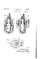
- F igure l is a sectional view taken substantially along the line 11 of Figure 3.
- Figure 2 is a sectional view taken substantially along the line 22 of Figure 3.
- Figure 3 is a plan view of a plug valve with the invention applied thereto.
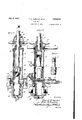
- Figure 4 is a sectional view showing a repairing apparatus and its associated parts connected to the valve casing.
- Figure 5 is a sectional view taken substa tially at rightangles to Figure 4.
- Figure 6 is a detail view of a reamer that may be connected to the operating shaft of the apparatus for cleaning the valve casing.
- the supply of fluid under pressure such as gas, steam, water or the like through the casing is preferably controlled by a rotary, axially slidable, greaseless plug valve 14 that may be tapered, so as to snugly engage a correspondingly shaped valve seat 15 formed in the wall of the casing.
- the bottom of the valve 14 is preferably formed with a threaded recess 16, which aligns with a correspondingly threaded openin lower portion of the casing, sai opening being normally closed by a plug 18, and 'slight- 1y larger than the recess 16.
- the valve 14 has a reduced stem 19, which extends upwardly through the casing and is provided with a threaded portion 20 and a polygonal shaped head 21 having a rib 22, so as to facilitate the connection of the stem with any suitable tool for imparting a rotary movement to the valve.
- a member 23 of any suitable shape and configuration which member is provided with an opening 24 through which extends the stem 19.
- the wall of the opening 24 is 17 in the the packing so as to compress the same against the valve stem.
- the valve 14 is moved axially into and out of engagement with its seat 15 preferably through the instrumentality of a lower operating nut 27 having a flange 28 and an externally threaded portion 29.
- the nut 27 is positioned above the member 23 and is connected to the stem 19 by a locking pin 30 arranged to fit in a longitudinally extending groove 31 in the stem, so that the nut 27 is non-rotatably connected to the stem but allows the stem to move axially relative thereto a limited distance.
- a clamping cap 32 has an internal flange 33 which engages the flange 28 on the nut 27 to prevent axial movement thereof.
- Bolts 34 extend through aligned openings in the casing 10, member 23 and cap 32 and receive the .nuts 35, to detachably secure these parts to the casing.
- an upper operating nut 36 Associated with the "lower operating nut 27 is an upper operating nut 36 that has spaced internal threaded portions 37 and 38 of difl'erent diameters and the threads preferably of different pitch, said portions being arranged to resepectively engage the complementary threads on the lower operating nut 27 and the threads on the stem 19. It will be seen that upon the rotation of the nut 36 in a clockwise direction, it will cause the valve stem 19 to move the valve 14 down into engagement with its seat 15. Conversel when the nut 36 is rotated in the opposite irection, the plug 14 is raised from its seat, so that it may be freely rotated by any suitable tool connected to the head 21 of the stem.
- the valve is forced into a positive and tight sealing engagement with its seat 15 when the nut 36 is actuated to close the valve and 1s qulckly raised therefrom when the nut 36 is turned in the opposite direction.
- the valve 14 may have a covering or a linlng 39 of any suitable resilient material such as rubber or the like, in order to provide a ,firm engagement of the valve with its seat when in the closed position, thus eliminating the necessity of employing grease or the like for msurmg the proper operation of the ug. Y
- a covering or a linlng 39 of any suitable resilient material such as rubber or the like
- This desired result is eflected by first removing the plug 18 from the bottom of the casing and substituting therefor a screw 40 of smaller diameter which extends through the opening 17, so as to be threadedly connected to the recess 16 in the valve 14 to prevent withdrawal of the valve from the cas' ing.
- the nuts 35 are then removed from the bolts 34 in order that the superstructure of the valve may be withdrawn.
- a repairing apparatus or housing 41 is then directly connected to the valve casing 10 by the bolts 34 and nuts 35, to replacethe member 23 and cap 32.
- a shaft or boring bar 42 extends into the housing 41 through a cap 43 and is provided at its lower end with a threaded socket 44 arranged to be detachably connected to the valve stem '19.
- the interior of the housing 41 constitutes a pressure chamber which is closed at its top by the cap 43 that has a packing 45 and gland 46, for preventing the escape of fluid between the shaft 42 and the cap.
- the cap 43 is provided with an externally threaded reduced portion 47 which carries the feed handle 48 that in turn is arranged to receive a yoke 49, that may engage either the upper or lower side of the collar 50 on the shaft 42, so as to exert an upward or downward force on the shaft as may be required.
- the by-pa'ss valve 53 is closed andthe pressure release valve 54-is opened, so that the valve 14 may bev withdrawn from the housing upon removal of the cap 43 and its associated parts therefrom.
- the cap 43 has an internally threaded lower end 55 which is detachably connected to the top of the housing 41 and may be readily applied or removed therefrom by thehandles 56.
- a suitable reaming tool 57 having a threaded stem 58 may be connected to the socket 44 of the shaft 42 after removal of the valve 14 therefrom.
- the housing 41 with the reamer mounted therein is then connected' to the casing 10 by.the bolts 35 and the pressure release valve 54 is closed and the by-pas's valve 53 opened, so as to build up pressure in the chamber.
- the slide valve 51 is moved to its open position, to. permit the insertion of the reamer 57 into the valve casing and the reamer is then forced into engagement with the valve seat 15 and this surface is re-finished by the rotation of the shaft 42.
- the yoke 49 is positioned above the collar 50 and a suitable handle or tool is connected to the outer end of the shaft 42 for rotating the same.
- the reamer is moved into the pressure chamber and the slide valve 51 closed in the manner as previously described and the valve 14 substituted for the reamer on the shaft 42, so as to be inserted into the casing.
- the valve 14 is temporarily held in position by the plug 40, which allows the removal of the housing 41 and its associated parts and the replacing of the regular valve superstructure.
- the screw 40 is then substituted for the plug 18 and the parts assume the position as shown in Figure 1.
- a valve of the class described including a body having a valve seat, a rotatable plug valve arranged to be moved into and out of engagement with said seat, said plug valve having its stem extending through said body, an operating nut non-rotatably but slidably connected to said stem and means threaded to said stem and said'nut for moving the plug valve relative to its seat.
- a valve of the class described including a body having a valve seat, a rotatable plug valve arranged to be moved into and out of engagement with said seat, said plug valve having its stem extending through said body, an operating nut non-rotatably but slidahly connected to said stem, means threaded to said stem and said nut for moving the plug valve relative to its seat, and means on said stem for rotating the plug valve when it is moved away from its seat.
- a valve of the class described including a body having a valve seat, a rotatable plug valve having a resilient cover arranged to be moved into and out of engagement with said seat, said plug valve having its stem extending through said body, an operating nut nonrotatably but slidably connected to said stem, and means threaded to said stem and said nut for moving the plug valve relative to its seat, whereby upon the plug valve being raised from its seat to permit the free rotation thereof in a predetermined axial position.
- a valve of the class described including a body having a valve seat, a rotatable and axially movable plug valve in said body for controlling the supply therethrough, said plug valve having a stem extending through said body, a member having an opening through which said stem passes, the wall of said opening having an annular recess, a
- a valve of the class described including i a casing having a tapered valve seat, a rotatable plug valve arranged to be moved axially into and out of engagement with said seat, said plug valve having a threaded stem extending through said casing, a member hav-' ing an opening through which said stem extends, the Wall of said opening being provided" with an annular recess, a packing in said recess and engaging said stem, operating -means having a portion threaded to such stem and a portion keyedlto the stem for moving the plug valve into and out of engagement with its seat, and means permitting the axial movement bf the stem relative to said operat-. ing means, whereby, upon the plug valve being raised from its seat, to permitv the free rotation thereof and the operating means in'a predetermined axial position.
- a valve of the class described including a casing having inlet and outlet openings, said casing being provided with a valve seat, a rotatable plug valve arranged to be moved axially into and out of engagement with sa d seat and contr' l the flow of fluid through said casing, said p ug valve having a threaded stem extending through said casing, a member having an) opening through which sald stem extends, the wall of said opening be ng I provided with an annular recess, a packmg mounted in said recess, a lower operating nut ha-ving'an external threaded portion, associated with said stem, a retaining cap engaging said nut, means securing said member and said cap to said casing, means non-rotatably connecting said lower, operating nut to said stem to permit axial movement of the stem relative thereto, and an upper operating nut having spaced internal threaded port ons engaging the complementary threaded portions 'on said lower retaining nut and valve stem,
- a .valve of the class described includhaving an external threaded portion, associated with said stem, a retaining cap engaging said nut, means securing said member and said cap to said casing, means non-rotatably connecting said lower operating nut to said stem to permit axial movement of the stem relative thereto, and an upper operat ng 7 nut having spaced internal threaded portions of different pitch engaging the complementary threaded portions on said lower retaining nut and valve stem, whereby when the plug valve is raised from its seat it may be maintained in any predetermined axial posi tion during the rotation thereof.
Landscapes
- Engineering & Computer Science (AREA)
- General Engineering & Computer Science (AREA)
- Mechanical Engineering (AREA)
- Mechanically-Actuated Valves (AREA)
Description
2' Sheets-Sheet l F. H., MUELLER ET AL PLUG STOP Filed July 2, 1951 July 4, 1933.
amnion Wank 12 may, Jrnes 71 6707 1'00 I I dcrmw July 4, 1933.
F. H. MUELLER El AL PLUG STOP 2 Sheets-Shet 2 Filed July 2, 1931 III/II Patented July 4, 1933 UNITED STATES PATENT OFFICE FRANK H. MUELLER AND JAMES W. SIMPSON, 0F DECATUR, ILLINOIS, ASSIGNORS m0 MUELLER 00., OF DECATUR, ILLINOIS, A CORPORATIONOF ILLINOIS PLUG STOP Application filed July 2, 1931. Serial No. 548,420.
The present invention relates to rotary valves or stops and more especially to improved means in the construction and operation of greaseless plug gas stops.
Heretofore, in valves of this type, it has been diificult to provide a valve construction in which the plug when removed from' its seat will be maintained in a desired raised or axial position upon rotation of the valve. Accordingly, it is one of the important features of the present invention to provide a simple, compact and eflicient plug valve in which means are provided whereby the valve when moved out of engagement with its seat may be maintained exactly in any predetermined axial position and be freely rotated without danger of being moved out of this position. 7
Another object consists in providing a gas stop in which the plug and its associated parts are so constructed and arranged as to eliminate the necessity of using grease or the like in order to insure the efficient operation of the device.
' A further object comprehends the provision of means for effecting the ready removal of'the valve from its casing without the necessity of first cutting off the flow of the supply or pressure in the supply main or the line to which the valve is connected, so that the parts may be conveniently withdrawn for the purpose of repair or renewal and access may be had to the interior of the valve in order that it may be cleaned by a suitable reaming tool or the like.
Other objects and advantages of the invention will become apparent from the following description when taken in conjunction with the accompanying claims and drawings. Referring to the drawings, in which is shown a preferred embodiment of the invention,
F igure l is a sectional view taken substantially along the line 11 of Figure 3.
Figure 2 is a sectional view taken substantially along the line 22 of Figure 3.
Figure 3 is a plan view of a plug valve with the invention applied thereto.
Figure 4 is a sectional view showing a repairing apparatus and its associated parts connected to the valve casing.
Figure 5 is a sectional view taken substa tially at rightangles to Figure 4.
Figure 6 is a detail view of a reamer that may be connected to the operating shaft of the apparatus for cleaning the valve casing.
body. The supply of fluid under pressure such as gas, steam, water or the like through the casing is preferably controlled by a rotary, axially slidable, greaseless plug valve 14 that may be tapered, so as to snugly engage a correspondingly shaped valve seat 15 formed in the wall of the casing. The bottom of the valve 14 is preferably formed with a threaded recess 16, which aligns with a correspondingly threaded openin lower portion of the casing, sai opening being normally closed by a plug 18, and 'slight- 1y larger than the recess 16.
The valve 14 has a reduced stem 19, which extends upwardly through the casing and is provided with a threaded portion 20 and a polygonal shaped head 21 having a rib 22, so as to facilitate the connection of the stem with any suitable tool for imparting a rotary movement to the valve. In order to prevent the escape of fluid from the casing past the valve stem 19, there is mounted on the casing a member 23 of any suitable shape and configuration, which member is provided with an opening 24 through which extends the stem 19. The wall of the opening 24 is 17 in the the packing so as to compress the same against the valve stem.
The valve 14 is moved axially into and out of engagement with its seat 15 preferably through the instrumentality of a lower operating nut 27 having a flange 28 and an externally threaded portion 29. The nut 27 is positioned above the member 23 and is connected to the stem 19 by a locking pin 30 arranged to fit in a longitudinally extending groove 31 in the stem, so that the nut 27 is non-rotatably connected to the stem but allows the stem to move axially relative thereto a limited distance. A clamping cap 32 has an internal flange 33 which engages the flange 28 on the nut 27 to prevent axial movement thereof. Bolts 34 extend through aligned openings in the casing 10, member 23 and cap 32 and receive the .nuts 35, to detachably secure these parts to the casing.
Associated with the "lower operating nut 27 is an upper operating nut 36 that has spaced internal threaded portions 37 and 38 of difl'erent diameters and the threads preferably of different pitch, said portions being arranged to resepectively engage the complementary threads on the lower operating nut 27 and the threads on the stem 19. It will be seen that upon the rotation of the nut 36 in a clockwise direction, it will cause the valve stem 19 to move the valve 14 down into engagement with its seat 15. Conversel when the nut 36 is rotated in the opposite irection, the plug 14 is raised from its seat, so that it may be freely rotated by any suitable tool connected to the head 21 of the stem. When the plug 14 rotates the bottom operating nut 27 is caused to rotate with it, due to the lockin engagement of the pin therewith. oreover, by virtue of the connection of the upper operating nut 36 with both the stem 19 and the lower nut 27, these pzrts will all rotate together and remain or heldexactly in any desired vertical position in which the valve may be placed durin the rotation of the valve. This is a de- "ci ed advantage over the usual mechanism heretofore employed, s1nce'1n such devices the nuts or retainin members have a tendency to drag and c ange the vertical position of the plug or valve, causing either a tightening or loosening of the plug, depending upon its directionof rotation. Because of the difierential screw threaded connection I of. the nut 36 with the nut 27 and the valve stem, the valve is forced into a positive and tight sealing engagement with its seat 15 when the nut 36 is actuated to close the valve and 1s qulckly raised therefrom when the nut 36 is turned in the opposite direction.
The valve 14 may have a covering or a linlng 39 of any suitable resilient material such as rubber or the like, in order to provide a ,firm engagement of the valve with its seat when in the closed position, thus eliminating the necessity of employing grease or the like for msurmg the proper operation of the ug. Y In .the event that the covering 39 on the valve becomes worn out or the. valve seat has been injured, means are provided to faclhtate the withdrawal of the valve and its associ- -ated parts from the casing without intermain. This desired result is eflected by first removing the plug 18 from the bottom of the casing and substituting therefor a screw 40 of smaller diameter which extends through the opening 17, so as to be threadedly connected to the recess 16 in the valve 14 to prevent withdrawal of the valve from the cas' ing. The nuts 35 are then removed from the bolts 34 in order that the superstructure of the valve may be withdrawn. A repairing apparatus or housing 41 is then directly connected to the valve casing 10 by the bolts 34 and nuts 35, to replacethe member 23 and cap 32. A shaft or boring bar 42 extends into the housing 41 through a cap 43 and is provided at its lower end with a threaded socket 44 arranged to be detachably connected to the valve stem '19. The interior of the housing 41 constitutes a pressure chamber which is closed at its top by the cap 43 that has a packing 45 and gland 46, for preventing the escape of fluid between the shaft 42 and the cap. The cap 43 is provided with an externally threaded reduced portion 47 which carries the feed handle 48 that in turn is arranged to receive a yoke 49, that may engage either the upper or lower side of the collar 50 on the shaft 42, so as to exert an upward or downward force on the shaft as may be required.
It will be seen that when it is desired to withdraw the valve 14 from the casing 10 for the purpose of inspection or renewal, the repair apparatus or housing 41 is attached to the casing in the manner as previously described, so as to assume the position as shown in Figure 4. The bolt 40 is withdrawn from engagement with the valve 14 and the plug 18 is substituted therefor in the bottom of the casing 10. The feed yoke 49 is then positioned below the collar 50, so that upon turning of the handle 48, the valve 14 will be raised by the shaft 42 from its seat and moved out of the casing 10 into the housing 41. When this position is reached the slide valve 51 (Fig. 5) is actuated through the handle 52 to its closed position, as shown in Figure 5. At the same time, the by-pa'ss valve 53 is closed andthe pressure release valve 54-is opened, so that the valve 14 may bev withdrawn from the housing upon removal of the cap 43 and its associated parts therefrom. The cap 43 has an internally threaded lower end 55 which is detachably connected to the top of the housing 41 and may be readily applied or removed therefrom by thehandles 56.
Shoud it be necessary to clean the valve seat 15, a suitable reaming tool 57 having a threaded stem 58 may be connected to the socket 44 of the shaft 42 after removal of the valve 14 therefrom. The housing 41 with the reamer mounted therein is then connected' to the casing 10 by.the bolts 35 and the pressure release valve 54 is closed and the by-pas's valve 53 opened, so as to build up pressure in the chamber. The slide valve 51 is moved to its open position, to. permit the insertion of the reamer 57 into the valve casing and the reamer is then forced into engagement with the valve seat 15 and this surface is re-finished by the rotation of the shaft 42. During the reaming operation the yoke 49 is positioned above the collar 50 and a suitable handle or tool is connected to the outer end of the shaft 42 for rotating the same.
After the casing has been cleaned the reamer is moved into the pressure chamber and the slide valve 51 closed in the manner as previously described and the valve 14 substituted for the reamer on the shaft 42, so as to be inserted into the casing. The valve 14 is temporarily held in position by the plug 40, which allows the removal of the housing 41 and its associated parts and the replacing of the regular valve superstructure. The screw 40 is then substituted for the plug 18 and the parts assume the position as shown in Figure 1.
It is to be understood that the form of the invention herewith shown and described is merely illustrative of a preferred embodiment of the invention and that such changes may be made as fall within the purview of one skilled in the art Without departing from the spirit of the invention and the scope of the appended claims.
We claim: y t
1. A valve of the class described including a body having a valve seat, a rotatable plug valve arranged to be moved into and out of engagement with said seat, said plug valve having its stem extending through said body, an operating nut non-rotatably but slidably connected to said stem and means threaded to said stem and said'nut for moving the plug valve relative to its seat.
2. A valve of the class described including a body having a valve seat, a rotatable plug valve arranged to be moved into and out of engagement with said seat, said plug valve having its stem extending through said body, an operating nut non-rotatably but slidahly connected to said stem, means threaded to said stem and said nut for moving the plug valve relative to its seat, and means on said stem for rotating the plug valve when it is moved away from its seat.
3; A valve of the class described including a body having a valve seat, a rotatable plug valve having a resilient cover arranged to be moved into and out of engagement with said seat, said plug valve having its stem extending through said body, an operating nut nonrotatably but slidably connected to said stem, and means threaded to said stem and said nut for moving the plug valve relative to its seat, whereby upon the plug valve being raised from its seat to permit the free rotation thereof in a predetermined axial position.
4. A valve of the class described including a body having a valve seat, a rotatable and axially movable plug valve in said body for controlling the supply therethrough, said plug valve having a stem extending through said body, a member having an opening through which said stem passes, the wall of said opening having an annular recess, a
packing in said recess .and engaging said stem, and means operatively connected to said stem for moving the plug valve relative to its seat, whereby, upon the plug valve being raised from its seat, to permit rotation of the valve in a predetermined position.
5. A valve of the class described including i a casing having a tapered valve seat, a rotatable plug valve arranged to be moved axially into and out of engagement with said seat, said plug valve having a threaded stem extending through said casing, a member hav-' ing an opening through which said stem extends, the Wall of said opening being provided" with an annular recess, a packing in said recess and engaging said stem, operating -means having a portion threaded to such stem and a portion keyedlto the stem for moving the plug valve into and out of engagement with its seat, and means permitting the axial movement bf the stem relative to said operat-. ing means, whereby, upon the plug valve being raised from its seat, to permitv the free rotation thereof and the operating means in'a predetermined axial position.
6. A valve of the class described including a casing having inlet and outlet openings, said casing being provided with a valve seat, a rotatable plug valve arranged to be moved axially into and out of engagement with sa d seat and contr' l the flow of fluid through said casing, said p ug valve having a threaded stem extending through said casing, a member having an) opening through which sald stem extends, the wall of said opening be ng I provided with an annular recess, a packmg mounted in said recess, a lower operating nut ha-ving'an external threaded portion, associated with said stem, a retaining cap engaging said nut, means securing said member and said cap to said casing, means non-rotatably connecting said lower, operating nut to said stem to permit axial movement of the stem relative thereto, and an upper operating nut having spaced internal threaded port ons engaging the complementary threaded portions 'on said lower retaining nut and valve stem,
whereby when the plug valve is raised from its seat it may be maintained in any predetermined axial position during the rotation thereof.
- 7. A .valve of the class described includhaving an external threaded portion, associated with said stem, a retaining cap engaging said nut, means securing said member and said cap to said casing, means non-rotatably connecting said lower operating nut to said stem to permit axial movement of the stem relative thereto, and an upper operat ng 7 nut having spaced internal threaded portions of different pitch engaging the complementary threaded portions on said lower retaining nut and valve stem, whereby when the plug valve is raised from its seat it may be maintained in any predetermined axial posi tion during the rotation thereof.
In testimony whereof we have hereunto set our hands.
FRANK'H. MUELLER. JAMES W. SIMPSON.
Priority Applications (1)
| Application Number | Priority Date | Filing Date | Title |
|---|---|---|---|
| US54842031 US1916632A (en) | 1931-07-02 | 1931-07-02 | Plug stop |
Applications Claiming Priority (1)
| Application Number | Priority Date | Filing Date | Title |
|---|---|---|---|
| US54842031 US1916632A (en) | 1931-07-02 | 1931-07-02 | Plug stop |
Publications (1)
| Publication Number | Publication Date |
|---|---|
| US1916632A true US1916632A (en) | 1933-07-04 |
Family
ID=24188779
Family Applications (1)
| Application Number | Title | Priority Date | Filing Date |
|---|---|---|---|
| US54842031 Expired - Lifetime US1916632A (en) | 1931-07-02 | 1931-07-02 | Plug stop |
Country Status (1)
| Country | Link |
|---|---|
| US (1) | US1916632A (en) |
Cited By (3)
| Publication number | Priority date | Publication date | Assignee | Title |
|---|---|---|---|---|
| US2620155A (en) * | 1946-01-26 | 1952-12-02 | Gar Wood Ind Inc | Axially movable rotary valve |
| US2759697A (en) * | 1950-10-20 | 1956-08-21 | Fred H Camphausen | Hydraulic control for butterfly valves |
| US3076632A (en) * | 1959-05-14 | 1963-02-05 | Mueller Co | Pipe line stopper |
-
1931
- 1931-07-02 US US54842031 patent/US1916632A/en not_active Expired - Lifetime
Cited By (3)
| Publication number | Priority date | Publication date | Assignee | Title |
|---|---|---|---|---|
| US2620155A (en) * | 1946-01-26 | 1952-12-02 | Gar Wood Ind Inc | Axially movable rotary valve |
| US2759697A (en) * | 1950-10-20 | 1956-08-21 | Fred H Camphausen | Hydraulic control for butterfly valves |
| US3076632A (en) * | 1959-05-14 | 1963-02-05 | Mueller Co | Pipe line stopper |
Similar Documents
| Publication | Publication Date | Title |
|---|---|---|
| US2763282A (en) | Pipe stopper fitting | |
| US1784094A (en) | Valve-operating means | |
| US2237476A (en) | Apparatus for fluid control | |
| US2649825A (en) | Wrench and tap device | |
| US2187838A (en) | Valve removing tool | |
| US1996345A (en) | Method of and apparatus for drilling and plugging mains and pipes and inserting and removing such plugs | |
| US1916632A (en) | Plug stop | |
| US2151594A (en) | Tapping machine | |
| US2343134A (en) | Discharge valve | |
| US2103536A (en) | Stopcock | |
| US2790677A (en) | Automatic self-cleaning shower heads | |
| US2217834A (en) | Valve construction | |
| US2996075A (en) | Valve construction | |
| US2123477A (en) | Valve | |
| US1792950A (en) | Orifice fitting | |
| US1379389A (en) | Valve | |
| US1669844A (en) | Rotating valve cock | |
| US2636514A (en) | Tank plug | |
| US2256416A (en) | Valve | |
| DE906874C (en) | Shut-off device, especially for milk pipes | |
| US1852233A (en) | Device for controlling the flow of fluid | |
| US1379388A (en) | Valve | |
| US1698439A (en) | Valve | |
| US2625172A (en) | Flow controlling device | |
| DE524598C (en) | Valve |