US1915744A - Valve - Google Patents
Valve Download PDFInfo
- Publication number
- US1915744A US1915744A US594665A US59466532A US1915744A US 1915744 A US1915744 A US 1915744A US 594665 A US594665 A US 594665A US 59466532 A US59466532 A US 59466532A US 1915744 A US1915744 A US 1915744A
- Authority
- US
- United States
- Prior art keywords
- section
- casing
- valve
- spider
- fixed
- Prior art date
- Legal status (The legal status is an assumption and is not a legal conclusion. Google has not performed a legal analysis and makes no representation as to the accuracy of the status listed.)
- Expired - Lifetime
Links
- 239000007789 gas Substances 0.000 description 15
- 241000239290 Araneae Species 0.000 description 13
- 239000000463 material Substances 0.000 description 4
- 150000001875 compounds Chemical class 0.000 description 3
- 230000004308 accommodation Effects 0.000 description 1
- 238000011109 contamination Methods 0.000 description 1
- 229940030980 inova Drugs 0.000 description 1
- 239000002184 metal Substances 0.000 description 1
- 231100000614 poison Toxicity 0.000 description 1
- 241000894007 species Species 0.000 description 1
Images
Classifications
-
- F—MECHANICAL ENGINEERING; LIGHTING; HEATING; WEAPONS; BLASTING
- F16—ENGINEERING ELEMENTS AND UNITS; GENERAL MEASURES FOR PRODUCING AND MAINTAINING EFFECTIVE FUNCTIONING OF MACHINES OR INSTALLATIONS; THERMAL INSULATION IN GENERAL
- F16K—VALVES; TAPS; COCKS; ACTUATING-FLOATS; DEVICES FOR VENTING OR AERATING
- F16K3/00—Gate valves or sliding valves, i.e. cut-off apparatus with closing members having a sliding movement along the seat for opening and closing
- F16K3/02—Gate valves or sliding valves, i.e. cut-off apparatus with closing members having a sliding movement along the seat for opening and closing with flat sealing faces; Packings therefor
- F16K3/04—Gate valves or sliding valves, i.e. cut-off apparatus with closing members having a sliding movement along the seat for opening and closing with flat sealing faces; Packings therefor with pivoted closure members
- F16K3/10—Gate valves or sliding valves, i.e. cut-off apparatus with closing members having a sliding movement along the seat for opening and closing with flat sealing faces; Packings therefor with pivoted closure members with special arrangements for separating the sealing faces or for pressing them together
Definitions
- This invention relates to valves and particularly to gas valves such as are ued to handle relatively large volumes of gases.
- One type of valve customarily used consists simply of a metal plate which is shoved between two sections of the pipe conducting the gases and bolted in place. Generally this plate is made goggle-shaped with an open and blind eye, the blind eye being boltedin piace as just mentioned and the open eye ing substituted when the valve 1s open.
- These valves are subject to the disadvantage that they are easily rendered inoperative by the rusting and lockin together of theV various bolts, journals an sliding surfaces and require extra supports in the gas mains.
- the valve embodied b y the present inven The valve embodied b y the present inven.
- Figure 1 is a vertical cross-section of a straightway form.
- Figure 2 is a cross-'section from the line lll--ll in the first figure.
- Figure 3 is a verticalcross-section of an angle form.
- the straightway valve will be described first.
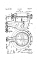
- a casing'l has a fixed gas conducting section 2 and a second similarly shaped section 3 which opposes the first and is mounted on a dat annular ring 4 of flexible material.
- a plate 5 is mounted on a pivot 6 for swinging movement between the two sections. Both surfaces of this plate adjacent its inner circumference and the edges of the two sections are ground smoothly.
- a spider ring 7 is fixed to the ring 4 adjacent the section 3.
- the casing 1 extends upwardly to accommodate the long end of a one-arm lever 8 which is fulcrumed in a socket 9 and fits through a hole in the spider 53 7
- the upper end of this lever is fixed to a shaft 1() which projects out ing 1 with which it is in relationship.
- the various 'rss PATENT .oi-Fica hrough the casscrew-threaded parts through which this lever projects have rounded surfaces which insure free operation.
- the 55 shaft 10 is operated by a hand wheel l1 in the present instance, although in large 4valves it may be found advantageous to use some sort of power drive.
- valve The operation of the valve is fairly ob- 0 vious.
- the plate 5 will 7 be relatively unsupported when the valve is open'it is referab y eral reen orcement 12.
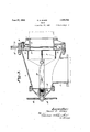
- the angle valve differs from the just described straightway valve in operating mechanism only.
- the mechanism consists simply of a rod 13 which is fixed to the spider4 7 and projects back towards the end of the casing 1, the latter being modified only ⁇ to the extent that the gases 9 are straight and of the Casin accommodation of the lever eliminated.
- a shaft 14 15 The shaft 14 is manually koperated by a hand wheel 16 although, as previously mentioned, a power drive motor may prove more suitable in some instances.
- the compound screw 15 is protected from scum or other gas contamination a diaphragm 17 interposed between it and the rod 13. The operation of this angle .y valve is substantially similar to that described in connection with the straightway the patent statutes, it not 1i this valve have accordance with itended to limit wo the scope off the invention exactly thereto, ex. ce t defined by the follow cla.
- a valve including a casey a ixed as conducting section in said Casin, a movale gas conducting section positione in said casing to oppose said fixed section, a plate arranged or swinging movement between said sections, a spider arranged in said casing and connected with said movable section, and means for moving said spider to operate said movable section.
- a valve including a casing, a ed gas conducting section in said casing, a movable conducting section positioned in said casing to oppose said fixed section, a plate arranged for swinging movement between said sections, a spider arranged in said casing and connected witli said movable section, a lever arranged in said casin and connected with said spider and a sha t xed to said lever and projecting through said casing, said shaft and casing being arranged in mutualscrew-threaded engagement.
- a valve including a casing, a fixed gas conducting section in said casing, a movable gas conducting section positioned in said caslng to oppose said fixed section, a plate arranged orswinging movement between said sentons, a spider arranged in said casing and connected with said movable section, a rod fixed to said spider, a shaft projecting through said casing and a compound screw connection between said shaft and rod.
- a valve including a casing, a aed gas Leraren conducting section in said casing, a movable gas conducting section in said casing, a flat ring of exible material carrying said movable section so as to oppose said fixed section,
- a plate arranged to swing between said sec-' ring of flexible material carrying said mov-4 able section so as to oppose said xed section, a plate arraned to swing between said sections, a spider t ed to said ring adjacem said movable section.
- a lever arranged in said casing to move said spider, and an outwardly projecting shaft arranged in screw-threaded engagement with said .casing and fixed to said lever.
- a valve including a casing, a fixed as conducting section in said casing, a Inova le gas conductingsection in said casing, a flat ring of dexible material carrying said movable section so as to oppose said fixed section, a plate arranged to swing between said sections, a spider fixed to said ning adjacent said movable section, a rod fixed to said spider, a shaft projectingv through said casing and a com ound screw connection between said sha and rod.
Landscapes
- Engineering & Computer Science (AREA)
- General Engineering & Computer Science (AREA)
- Mechanical Engineering (AREA)
- Mechanically-Actuated Valves (AREA)
- Sliding Valves (AREA)
Description
Patented June 27, 1933 ran STA VALVE Application med. February 23, 1932. Serial No. 594,665.
This invention relates to valves and particularly to gas valves such as are ued to handle relatively large volumes of gases. One type of valve customarily used consists simply of a metal plate which is shoved between two sections of the pipe conducting the gases and bolted in place. Generally this plate is made goggle-shaped with an open and blind eye, the blind eye being boltedin piace as just mentioned and the open eye ing substituted when the valve 1s open. These valves are subject to the disadvantage that they are easily rendered inoperative by the rusting and lockin together of theV various bolts, journals an sliding surfaces and require extra supports in the gas mains.
The valve embodied b y the present inven.
tion is intended to obviate the above mentioned objectionable features. Further, .it is to be capable of being operated much more quickly, which isa great advantage, for instance, when handling blast furnace gases. Other attainments of the invention will be understood from the following disclosure.
Having reference vto the accom anying drawings, which illustrate two speci c forms of the invention:
Figure 1 is a vertical cross-section of a straightway form.
Figure 2 is a cross-'section from the line lll--ll in the first figure.
Figure 3 is a verticalcross-section of an angle form.
The straightway valve will be described first.
A casing'l has a fixed gas conducting section 2 and a second similarly shaped section 3 which opposes the first and is mounted on a dat annular ring 4 of flexible material. A plate 5 is mounted on a pivot 6 for swinging movement between the two sections. Both surfaces of this plate adjacent its inner circumference and the edges of the two sections are ground smoothly.
A spider ring 7 is fixed to the ring 4 adjacent the section 3. The casing 1 extends upwardly to accommodate the long end of a one-arm lever 8 which is fulcrumed in a socket 9 and fits through a hole in the spider 53 7 The upper end of this lever is fixed to a shaft 1() which projects out ing 1 with which it is in relationship. The various 'rss PATENT .oi-Fica hrough the casscrew-threaded parts through which this lever projects have rounded surfaces which insure free operation. The 55 shaft 10 is operated by a hand wheel l1 in the present instance, although in large 4valves it may be found advantageous to use some sort of power drive.
The operation of the valve is fairly ob- 0 vious.
Rotation of the shaft 10 lin one direction will move the section 3 away from the section 2 permitting movement of the plate When this plate is tion it will be hugge in closed posion either side by the 5 two sections in a gas-tight manner. When the plate is withdrawn so that the valve is open the two sections arel shoved together so that their ground edges coact whereby a gastight conduit is formed. As
the plate 5 will 7 be relatively unsupported when the valve is open'it is referab y eral reen orcement 12.
provided with a periph- The angle valve differs from the just described straightway valve in operating mechanism only.
its spider ring Here the mechanism consists simply of a rod 13 which is fixed to the spider4 7 and projects back towards the end of the casing 1, the latter being modified only` to the extent that the gases 9 are straight and of the Casin accommodation of the lever eliminated.
rThis rod 13 is operated through a compound screw directed right-angularly instead of the upwardly `projecting partk shown in the first instance for 8 is, of course,
by a shaft 14 15. The shaft 14 is manually koperated by a hand wheel 16 although, as previously mentioned, a power drive motor may prove more suitable in some instances. The compound screw 15 is protected from scum or other gas contamination a diaphragm 17 interposed between it and the rod 13. The operation of this angle .y valve is substantially similar to that described in connection with the straightway the patent statutes, it not 1i this valve have accordance with itended to limit wo the scope off the invention exactly thereto, ex. ce t defined by the follow cla.
c aim:
l. A valve including a casey a ixed as conducting section in said Casin, a movale gas conducting section positione in said casing to oppose said fixed section, a plate arranged or swinging movement between said sections, a spider arranged in said casing and connected with said movable section, and means for moving said spider to operate said movable section.
2., A valve including a casing, a ed gas conducting section in said casing, a movable conducting section positioned in said casing to oppose said fixed section, a plate arranged for swinging movement between said sections, a spider arranged in said casing and connected witli said movable section, a lever arranged in said casin and connected with said spider and a sha t xed to said lever and projecting through said casing, said shaft and casing being arranged in mutualscrew-threaded engagement.
3. A valve including a casing, a fixed gas conducting section in said casing, a movable gas conducting section positioned in said caslng to oppose said fixed section, a plate arranged orswinging movement between said sentons, a spider arranged in said casing and connected with said movable section, a rod fixed to said spider, a shaft projecting through said casing and a compound screw connection between said shaft and rod.
l. A valve including a casing, a aed gas Leraren conducting section in said casing, a movable gas conducting section in said casing, a flat ring of exible material carrying said movable section so as to oppose said fixed section,
a plate arranged to swing between said sec-' ring of flexible material carrying said mov-4 able section so as to oppose said xed section, a plate arraned to swing between said sections, a spider t ed to said ring adjacem said movable section. a lever arranged in said casing to move said spider, and an outwardly projecting shaft arranged in screw-threaded engagement with said .casing and fixed to said lever.
6. A valve including a casing, a fixed as conducting section in said casing, a Inova le gas conductingsection in said casing, a flat ring of dexible material carrying said movable section so as to oppose said fixed section, a plate arranged to swing between said sections, a spider fixed to said ning adjacent said movable section, a rod fixed to said spider, a shaft projectingv through said casing and a com ound screw connection between said sha and rod.
ln testimony whereof, l have hereunto set my hand.
FRANK R. MGGEE.
Priority Applications (1)
| Application Number | Priority Date | Filing Date | Title |
|---|---|---|---|
| US594665A US1915744A (en) | 1932-02-23 | 1932-02-23 | Valve |
Applications Claiming Priority (1)
| Application Number | Priority Date | Filing Date | Title |
|---|---|---|---|
| US594665A US1915744A (en) | 1932-02-23 | 1932-02-23 | Valve |
Publications (1)
| Publication Number | Publication Date |
|---|---|
| US1915744A true US1915744A (en) | 1933-06-27 |
Family
ID=24379859
Family Applications (1)
| Application Number | Title | Priority Date | Filing Date |
|---|---|---|---|
| US594665A Expired - Lifetime US1915744A (en) | 1932-02-23 | 1932-02-23 | Valve |
Country Status (1)
| Country | Link |
|---|---|
| US (1) | US1915744A (en) |
Cited By (1)
| Publication number | Priority date | Publication date | Assignee | Title |
|---|---|---|---|---|
| US2649117A (en) * | 1946-08-30 | 1953-08-18 | Paul A Dewhirst | Pipe line fitting |
-
1932
- 1932-02-23 US US594665A patent/US1915744A/en not_active Expired - Lifetime
Cited By (1)
| Publication number | Priority date | Publication date | Assignee | Title |
|---|---|---|---|---|
| US2649117A (en) * | 1946-08-30 | 1953-08-18 | Paul A Dewhirst | Pipe line fitting |
Similar Documents
| Publication | Publication Date | Title |
|---|---|---|
| US4190074A (en) | Pressure equalization valve and technique for shaft furnace | |
| US2770477A (en) | Mechanical seal | |
| US3843090A (en) | Damper | |
| US2344594A (en) | Motor operated toggle valve | |
| US2144417A (en) | Sludge pump | |
| US3471121A (en) | Butterfly valve | |
| US1915744A (en) | Valve | |
| US3207174A (en) | Fluid cooled valve | |
| US2133487A (en) | Liquid sealed rotating joints | |
| US2892609A (en) | Compound-movement butterfly valve | |
| US3047024A (en) | Slide valve | |
| US2165874A (en) | Valve | |
| US2354987A (en) | Toggle operated valve | |
| US2370604A (en) | Valve actuating means | |
| US2267057A (en) | Valve | |
| US2334663A (en) | Seal for rotary kilns | |
| US1386792A (en) | Rotary blower | |
| US2455539A (en) | Joint construction | |
| US3013766A (en) | Spherical valve | |
| US2724978A (en) | Valve operator | |
| CN204153175U (en) | The quick detachable sealing configuration of ultralow temperature polytetrafluoroethylsealed sealed butterfly valve | |
| US3638674A (en) | Gastight damper having an inflatable seal | |
| US2157263A (en) | Valve actuating mechanism | |
| US2273720A (en) | Valve | |
| US3741522A (en) | Gate valve |