US1911707A - Phonograph - Google Patents
Phonograph Download PDFInfo
- Publication number
- US1911707A US1911707A US1911707DA US1911707A US 1911707 A US1911707 A US 1911707A US 1911707D A US1911707D A US 1911707DA US 1911707 A US1911707 A US 1911707A
- Authority
- US
- United States
- Prior art keywords
- record
- carrier
- tone arm
- switch
- arm
- Prior art date
- Legal status (The legal status is an assumption and is not a legal conclusion. Google has not performed a legal analysis and makes no representation as to the accuracy of the status listed.)
- Expired - Lifetime
Links
- 239000000969 carrier Substances 0.000 description 248
- 230000001276 controlling effect Effects 0.000 description 24
- 230000000875 corresponding Effects 0.000 description 22
- 230000000051 modifying Effects 0.000 description 10
- 230000000694 effects Effects 0.000 description 8
- 239000004020 conductor Substances 0.000 description 6
- OKTJSMMVPCPJKN-UHFFFAOYSA-N carbon Chemical compound [C] OKTJSMMVPCPJKN-UHFFFAOYSA-N 0.000 description 4
- 229910052799 carbon Inorganic materials 0.000 description 4
- 230000000717 retained Effects 0.000 description 4
- 239000007787 solid Substances 0.000 description 4
- 210000003414 Extremities Anatomy 0.000 description 2
- CMWTZPSULFXXJA-VIFPVBQESA-N Naproxen Chemical compound C1=C([C@H](C)C(O)=O)C=CC2=CC(OC)=CC=C21 CMWTZPSULFXXJA-VIFPVBQESA-N 0.000 description 2
- 241000681094 Zingel asper Species 0.000 description 2
- 230000001133 acceleration Effects 0.000 description 2
- 238000010586 diagram Methods 0.000 description 2
- 239000002184 metal Substances 0.000 description 2
- 230000000737 periodic Effects 0.000 description 2
- 230000001105 regulatory Effects 0.000 description 2
- 230000035939 shock Effects 0.000 description 2
- 230000001340 slower Effects 0.000 description 2
Images


Classifications
-
- G—PHYSICS
- G11—INFORMATION STORAGE
- G11B—INFORMATION STORAGE BASED ON RELATIVE MOVEMENT BETWEEN RECORD CARRIER AND TRANSDUCER
- G11B17/00—Guiding record carriers not specifically of filamentary or web form, or of supports therefor
- G11B17/22—Guiding record carriers not specifically of filamentary or web form, or of supports therefor from random access magazine of disc records
- G11B17/24—Guiding record carriers not specifically of filamentary or web form, or of supports therefor from random access magazine of disc records the magazine having a toroidal or part-toroidal shape
Definitions
- This invention relates to an automatic phonograph in which provision is made for automatically selecting and playmg any one of a series of records which are mounted upon a carrier by which they are moved to and from a playing station.
- the invention contemplates a machine of this character which may be adapted for coin operation.
- One of the objects of the invention 1s to provide in a machine of this character a cam device in which the actuating cam element forms a partof a unitary structure including the record carrier which is periodically' rotated to change from one record to another.
- Another object of the invention is to provide in combination with said rotatable structure means operable by the actuating cam .for controlling the record playing and drivlng 'mechanism in timed relation to the movement record to the other may be automatically effected without jarring the mechanism or in any way interferring with the action of the carrier in presenting successive or selected records to the playing station.
- a further object of the invention is to provide a tone arm which is pivoted to swing about both a horizontal and a vertical axis whereby the arm may be swung into and out of a playing position withoutinterferring with the adjacent record supports.
- a still further object of the invention is to provide speed control means controlled by the movement of the tone arm to automatically regulate th'e movement of the record carrier.
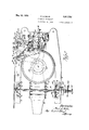
- Fig. 1 is an elevational view showing a portion of the record carrier and the associated reproducer assembly, the tone arm being shown in position-to start the playing of a record;
- Fig. 2 is a top plan view-0f a .portion of the record carrier and the associated repro- 50 ducer assembly, the position of the tone arm reproducer assembly showing the tone arm of the carrier so that the change from one at the beginning of the record being shown in solid lines, and the position of the tone arm at the end of the record being shown in dotted lines; l
- Fig. -3 is a side elevational view, partly in section, looking toward the record carrier from the right hand side of the machine, viewing 1;
- Fig. 4 is a detail elevational view of the p ioved to the inactlve or non-playing posilon.
- Fig. 5 is a detail section taken on the line 5 5 of Fig. 3 showin the upper portion of the reproducer assemb y;
- F ig. 6 is a detail of the coin control cut-out switch, taken on the line 6 6 of Fig. 3;
- Fig.- 7 is a detail section of the tone arm, the section being taken immediately forward of the tone arm supporting bracket;
- Fig. 8 is a broken detail section of one of the record supports; .and
- Fig. 9 is-a wiring diagram of the various electrical circuits employed in the machine.
- the record carrier comprises a series of radially disposed record holders 10, secured by means of screws 11 to a hub 12, which is mounted on a horizontal shaft 13, said shaft being journaled in uprights 14 which are in turn secured to a base 15 by bolts 16.
- Each of the record holders 10 is provided with a central aperture for receiving record supporting spindles 17, which in turn support recordcarrying plates or discs 18.
- the records 19 are removably secured to the record-carrying discs'18 by means of a spring clamp 20, shown in detail in Fig. 8.
- the spindle 17 is provided centrally with a bore in which is retained a spring-pressed button 21, the upper end of which is rounded and bears against a clip 22 which is provided with a slot 23 for receiving a pin 24, said pin extending between ears 25 on the, upper end of the spindle 17. It will be apparent that by shifting the clip 22 laterally until the pin 24 is at the extremity of the slot, the clip may be pivoted about the pin 24 into vertical position, whereupon the record 19 may. be removed.
- a notch 22, formed in t e end of the clip 22, vreceives the upper end of the button 21 when the clip is in the vertical po.-
- Thespindle 17 is revolubly mounted in a sleeve 27 which is fixedly secured to the record holder 10 by means of a cap 28 which has screw threaded engagement with a shoulder portion 29 of the sleeve 27.
- a bearing 30 affords free rotation for the s indle17 in the sleeve 27
- the lower end o the spindle 17 is provided with a stud 31, the free end of which is threaded to vreceive a lock nut 32 which bears against a flan ed collar 33 thereby retaining the spindle 1 within said sleeve 27.
- the record-carrying d isc orplate 18 is fixedly secured to the spindle 17, and may conveniently be made of sheet metal, the circumferential edge being turned down as shown at 34 to alord a bevelled face for a friction drive.
- a felt pad 35 may be placed on the upper face of the record plate 18 to afford a soft surface for engaging the under face of the'record.
- motor 36 which thus effects a movement of the record carrier, is adapted to de-energized as the record to be played 1s brought to the playing station, leaving the recordcarrier stationary until such record h as been completed after which the motor is agaln energized and turns said record carrier suiciently to bring the next or a selected record to the playing station.
- the reproducer assembly Associated with the record carrier 1s a reproducer assembly adapted to play. the record which has been brought into positlon by s aid carrier.
- the reproducer assembly comprises a tiltably mounted tone arm support 40, to
- tone arm 41 which is pivotally secured a tone arm 41, said arm being provided with a pick-up element 42 which has a needle 43 for engaging the sound grooves ⁇ of the records 19.
- the tone arm support 40 is pivotally mounted at 44 to an upright 45 which in turn is secured to the base 15 by the bolts 46.
- the tone arm 41 is arranged for double pivotal movement relative to the tone arm support 40.
- a pin 47 (see Fig. 7) which pivotally secures a bracket 48 to the tone arm support 40, and said bracket 48 is provided with a pair of spaced ears 49 between which extends a pin 50 upon which the tone arm 41 is pivotally mounted to permit it to Aswing about a horizontal axis.
- the pivotal movement of thetone arm 41 about the pin 50 allows the needle to follow irregularities or undulations n which the record carin themovement of the record, and the pivotal movement of said arm about the pin 47 yallows it to swing across the record from the position shown by the solid lines in Fig. 2 to that shown by the dotted lines in said figure as the playing of the record progresses.
- the tone arm support 40 is automatically tilted from the position shown in Fig. 1 to that shown in Fig. 4. During this movement the tone arm 41 pivots about the pin 47 to assumea folded position adjacent t e tone arm support 40 as shown in Fig. 2.
- a stop flange 57 carried by the tone arm 41 serves to limit the return movement of the arm as it is tilted into nonplaying or inactive position (see Figs. 5 and 7).
- a downwardly inclined arm 58 Aextends laterally from the tone arm support 40 to afford a support for the tone arm 41 during the interval in which the reproducer assembly is being tilted from the vertical position into the horizontal position preparatory to playing the record.
- the mechanism for this purpose comprises a large cam ring 59 (see Fig. 1) circumferentially disposed about the record carrier and secured thereto by cleats 60 which may be formed as an integral part of the record holders 10.
- the cam ring 59 is preferably made up of a series of cam unit segments which are joined end for end. to form the complete cam ring. Ihe adjacent ends of the cam segments are Joined to the cleats 60 by means of the bolts 61.
- Each of the cam segments is cut to form a cam groove 62, adapted to engage a roller 63, carried by the lower free end of a lever 64 which is pivotally supported at 65 to a yoke 66, secured to the base 15, said yoke' including a pair of vertical arms 67 and 68 between the upper free ends of which the lever 64 is supported.
- the upper end of the lever 64 is provided with a hook 69 adapted to engage a lug ⁇ 70 on the lower free end of the tone arm bracket 40.
- the cam roller 63 in following the (preripheral surface of the cam ring 59, will op into the camring groove 62, which movement will in turn pivot the lever 64 1n a clockwise dlrection, viewing Fig. 1, thereby permitting the tone arm support 40 to turn 1n a counter-clockwise direction upon its pivot 44 to lower the tone arm 41 into horizontal ositivon preparatory to playing a record.
- the record carrier is subsequently turned to remove the record from the playing station the roller 63 is projected outwardly by the cam groove 62 which in turn, through the movement of the lever 64, throws the tone arm support 40 and the tone arm 41 into the vertical or in- A active position shown in Fig. 4.
- the records are driven by a disc drive motor 71 provided with a drive shaft 72, the upper free end 'of which is equipped with a friction wheel 73 which is adapted to engage the bevelled face 34 of the record sup- .porting plate or disc 18.
- the motor is angularly mounted in a yoke 74 which is secured to the base plate 15, said yoke including vertical'arms 75 and 76 between which extends shaft 77 which in turn affords pivotal support for arms-7 8 and 79 rigidly affixed to the shell of the motor 71.
- the speed of the motor is regulated by a ball governor 8O mounted on the drive shaft 72.
- a brake shoe 81 is carried on the free end of a lever 82 (see Fig. 2) which is pivoted at 83 to an arm 84 carried on the upper end of the motor supporting member 79.
- the brake shoe 81 is thus mounted to swing with the disc motor 71 and is at all times in a position to engage a friction disc 85 carried by the governor when said disc is moved upwardly due to the extension of the balls of said governor carried by centrifugal force in the rotation of the motor shaft.
- An adjusting screw 86 is provided to regulate the position of the shoe 81 relative to the friction disc 85.
- the rotation of the record carrier is not only adapted, as previously pointed out, to control the movement of the reproducer assembly, but is also utilized to control the tilting movement of the disc motor 71 to bring the drive wheel 73 into engagement with a record plate 18 after the latter has been brought into position at the playing station.
- the motor 71 is provided with an apron 87, secured to the shell of the motor, and equipped with a roller 88 which is positioned to engage a cam surface 89 formed in the lever 64 (see Figs. 1 and 4).
- roller 88 in turn follows the cam surface 89 in the lever 64 thereby allowing the disc motor 71 to pivot in a counter-clockwise direction to bring the, drive wheel 73 into engagement with the edge of therecord. plate 18.
- a coil spring 90 secured at one end to alu 91 upon the motor shell and at the other end to alu 92 on the lever 64, serves to draw the motor 1 forwardl to keep the roller 88 in engagement with t e cam surface89 on the lever 64. Said spring 90 also serves to hold the roller 63 on the lower end of the lever 64 in engagement with the cam ring 59.
- the disc motor 71 is positioned to be in the main. circuit at all times and is designed to be in continuous operation until the main circuit is automatically opened by a suitable multiple Vcoin control.
- the mechanism for actuatingthe coin control comprises an arm 96 pivoted at 97 to the tone arm support 40 and normally held ⁇ in the position shown in said Figs. 5 and 6 by a spring 98, which is secured at one end to the tone arm support 40 and at the other end to the upper free end of the arm 96; and an arm 99, pivotally mounted at 100 on the upright 45, and provided with a s ring held contact 101 adapted to make and break a circuit with the contact102.
- a spring 103 extending between a fixed point on the upright 45 and the arm 99, normally holds the contacts 101 and 102 apart.
- a stud 104 on the lower end ofthe arm 96 momentarily engages the free end of the arm 99 and completes the multiple coin con- ⁇ trol circuit by closing the terminals 101 and 102. If the number of pieces corresponding to the number of coins inserted have been plaed the main circuit will automatically be bro en by the multiple coin control mechanism and the disc motor 71 will be shut ofi'.
- the record changing motor 36 is arranged in the circuit yto effect a periodic change of the records and necessarily must be shut oii' during the interval that the record is being played.
- an automatic double acting switch which is controlled by the movement of the tone arm 41 to start the record changing motor 36 immediately upon the completion of the playing of the record.- This switch is best shown in Figs.
- It comprises a double throw arm 105 pivotally mounted at 106 on a switch plate 1.07, which in turn is supported on the upright 45.
- One end of the arm 105 is provided with a toothed rack 108, the teeth of said rack being arranged to engage a pawl 109 which is pivotally mounted at.110 on a bracket 111, said bracket being carried by an arm 112 which :forms a part of the tone arm 41.
- a stop 111a limits the turning ofthe pawl 109 on the pivot 110 when the tone arm 41 is tilted into inoperative position. As the tone arm 41. is drawn across the record by the sound grooves, the pawl 109 rides across the rack 108.
- the record is of the type which is provided at the end of the piece with an eccentric groove such as is shown at 113
- the reverse movement of the tone arm caused by the needle riding in the eccentric groove will cause the pawl 109 to engage the rack 108 which in turn moves the switch arm 105 into enga ement with a contact arm 114, said arm 114 eing also pivotally mounted on the switch plate 107.
- the circuit is thereupon completed through contacts 115 and 116 car-- ried by the switch arm 105 and the contact arm 114, respectively, to thereupon energize the record changing' motor 36.
- the pawl 109 completely traverses the teeth on the rack 108 and engages a stop 118 to throw the switch arm 105 into engagement with a contact arm 119,'which in turn completes a circuit through contacts 120 and 121, carried by the switch arm 105 and the contact arm 119, respectively, to energize the record changing motor 36.
- the contact arms 114 and 119 are provided With depending ears 122 and 123, respectively, -which engage the edge of the switch plate 107 to prevent the arms from being drawn together under the action of spring 124 which extends between the arms adjacent their points of pivotal support on the switch plate 107
- the switch arm 105 is normally held midway between the arms 114 and 119 by a spring 125 which is secured at one end to the arm and at the other end to a fixed point on the switch plate 107.
- This automatic tone arm switch forms the subject matter of my co-pending application Serial No. 427,360, filed February 10, 1930, which has become Patent #1,889,786, dated Dec. 6, 1932.
- a contact arm 126 which is ivotedat 127 to an insulating plate ⁇ 128, w ⁇ ich in turn is secured at 129 to the upright 45.
- the upper end of the contact arm 126 is provided with a contact 130, and the insulating plate128 is provided with a contact 131, the circuit through the record changing motor 36 being completed through these contacts.
- the running switch is automatically closed to carry the circuit through the record changing motor by the movement of the lever 64 -whiclr-is provided with a shoe 132 positioned to engage the lower end of the contact arm 126.
- a helical spring 133 secured at one end to the upright and at the other end to the contact arm 126, serves to normally hold the lower end of said arm against the shoe 132.
- a supporting lever 134 is pivoted at 135 to the upright 45 and is curved downwardly at its forward end to engage the lower edge of the tone arm support 40.
- 'A helical spring 136 is secured at 137 to the forward end of the-lever 134 and is secured at the other end to the upright 45. Under the action of this spring the support member 134 checks the downward movement of the reproducer assembly as it is tilted into the horizontal position preparatory to playing.
- rlhe tone arm 41 is projected across the smooth preipheral portion 138 on the record 19 by means of a lever 139 which is pivoted at 140 to the tone arm support 40.
- the lower end ofthe lever 139 is provided with a flange 141, and the other end of the lever is secured to a helical sprin 142' which is secured to a fixed point on t e tone arm support 40.
- the ange 141 is positioned to engage the face of an adjustable screw 143 mounted in a cleat 144 which is secured to the tone arm 41.
- the spring 142 turns the lever 139 sufliciently to project the needle across the marginal ring 138 to start it in the first roove of the record.
- the screw 143 may e adjusted to control the distance which the tone arm 4l is thus initially advanced by the lever 139.
- the eXtreme lower end of the lever 139 may be provided with a bu'er 145 which absorbs the shock incident tothe folding of the tone arm 41 back against the tone arm support 40 when the reproducer assembly is raised.
- the control mechanism includes means for selecting any one of the records 19 without the need of playing records which may intervene between the record which has just been played and the next desired record.
- a selector latch 146 shown in Figs. 1 and 4, which is provided near one end with a shoulder 147 adapted to engage the roller 63 on the lower end of the lever 64.
- the roller 63 When in the unlatched position, as shown in Fig. 1, the roller 63 is free to drop into the cam groove 62 to permit the corresponding record to be-played, but when the roller 63 is engaged by the notch 147, as shown in Fig.
- the movenent of the latch 146 is controlled by a magnet 148, the armature 149 of which is pivotally mounted at 150 to the base 15.
- the latch 146 is pivoted at 151 to the armature 149 and is yieldingly held against the cam roller 63 by aspring 152, secured at one end to the latch and at the other end to the armature.
- the selector mechanism for controlling the magnet 148 is shown in Figs. 1, 2 and 9. It comprises a selector element 153 mounted to lturn with the shaft 13, and a second selector element 154 mounted to turn with a shaft 155, which rotates independently of the shaft 13.
- a dial 156 controlled through a ratchet 156a by a knob 157, is provided with numerals as indicated at 158, said numerals indicating the records corresponding to like numbers indicated on a suitable chart.
- the dial 156 is turned until the number corresponding to that record is opposite an indicator 159, whereupon a circuit which normally energizes the magnet 148 through the selector elements 153, 154, and a conductor 153, (see Fig.
- the tone arm 41 is arranged to automatically control the speed of the record changing motor 36.
- a tone arm switch 160 shown in Fig. 2.'
- the switch comprises a pair of spring contact arms 161 and 162 which are carried by the tone arm support member 40 and are provided on their outer free ends with contacts 163 and 164 respectively.
- the tone arm 41 carries a cam stud 165 which normally holds the contact 163 against the contact 164, as shown in Fig. 2.
- the cam stud 165 is removed from engagement with the arm 161 and opens the circuit between the contacts 163 and 164.
- the switch 160 is closed when the tone arm is raised and folds back against the tone arm support. As will hereinafter be pointed out in the description of Fig. 9, this automatically cuts out part of a resistance which is shunted across the armature of the record changing motor 36.
- a speed control switch 166 (see Figs. 1 and 4) is provided to further control the speed of the record changing motor 36 during the interval of the record change. It comprises a switch arm 167 pivotally mounted at 168 to an upright 169 which in turn is secured to the base 15; and a Contact arm 170 mounted on the upright 169 adjacent the lower end of the switch arm 167.
- the switch arm 167 is provided at its upper end with a roller 171 which normally is held against the shell of the motor 71 by a spring 172, which is secured at one end to the switch arm 167 and at the other end to a fixed point on the upright 169.
- the switch 166 When the disc'motor 71 pivots into playing position the switch 166 is closed, which action throws a part of the resistance in the shunt circuit across the armature of the record changing motor 36 and chokes the speed ofthe motor.
- the tone arm switch 160 in conjunction with the speed control switch 166, not only automatically adjusts the speed of the record changin motor to eliminate unnecessary delay inci ent to the changing of the records but also slows the carrier down sufhciently to give the running switch plenty of time to open and stop the carrier at the proper point for the next record. This deceleration also insures gradual lowering of the needle onto the record, thereby avoiding danger of breaking the record or damaging the needle by sudden impact.
- Fig. 9 I have shown a diagrammatic sketch of the electrical circuits and their reation to the various parts of the phonograph mechanism. A rough outline of certain of the parts of the phonograph mechanism is shown so that by reference to the corresponding numbers on the other figures the relation of these parts to the circuits will be readily understood.
- the main circuit is taken from a plug 175 to a fuse block 176, from which one side of the line is carried by the wire 177 to a ⁇ converter connecting block 178, and from there by a wire 179 to the terminal block 180.
- the other side of the line is taken from the fuse block 176, through the wire 181, to the terminal block 182, and from there by the wire 183 4through the carbon terminals 184, 185 and 186 of the multiple coin control device, back through the wire 187 to the terminal block 182.
- the wire 188 carries this side of the Y circuit from that point down to the converter connecting block 178 from which'point the4 Wire 189 leads back to the terminal block 180.
- the two sides of the line are thence taken from the terminal block 180 by the wires 190 and 191 to the terminal block 192, from which block the various circuits 'are taken which feed the various working parts of the phonograph. It might be added that wherever alternating current is available it is not necessary to use the converter connecting block 178, the object of this block being merely to adapt the apparatus for use where only direct current is available.
- the disc motor 71 is placed directly across the main line terminals on the terminal block 192 and accordingly is continuously in operation until the main line is interrupted by the multiple coin control which is automatically returned one step toward circuit breaking position when the magnet 193 is energized by the completion of a circuit through the contacts 101, 102.
- the record changing motor 36 is fed from the terminal block 192 by the wire 194, the circuit being through the armature of the motor, thence through the wire 195 back to the terminal block 192, through the wire 196 to the arms 114 and 119 of the double acting cut-off switch, and thence through the wire 197 back to the main line terminal on the block 192.
- the record changing motor 36 therefore, is periodically operated through the combined action of the double throw cutoil switch and the running switch 126 which is inserted between the wires 196 and 197 leading to the double throw cut-off switch.
- the speed of the record changing motor 36 is controlled by the tone arm switch 160 and the speed control switch 166.
- This speed control is effected by shunting across the armature of the motor a iixed resistance 198, a portion ⁇ 198* of which is arranged to be automatically y cut out upon the closing of the tone arm j switch 160, and the balance 198b of which remains shunted across the armature of the motor 36 until the speed control switch 166 is opened.
- a variable resistance 199 may be inserted in series with the fixed resistance 198 to control the amount of resistance which is shunted across the armature of the record changing motor 36.
- the resistances 198 and 198b act as a choke for controlling the speed of the record changing motor 36.
- the switch 166 When the reproducer assembly is lowered to play another record the switch 166 is closed which again places the shunt circuit across the armature of the motor 36. At this time, however, only the variable resistance 199 and the portion 198b of the resistance 198 are in the shunt circuit, the portion 198'* remaining cut out until the tone arm again moves across the record and opens the switch 160. The speed of the motor 36 is therefore cut down considerably since a good portion of the resistance is removed from the shunt circuit. As the roller 63 drops into the cam groove 62 the record changing motor 36 is therefore moving quite slowly and ample time is allowed to bring the record to rest atthe proper la 1n osition.
- p 'lyhegmragnet 148 controlling the selector latch 146, is fed from the main circuit through the wires 194 and 200, the return being through the wires 201, the'selector element 153, the conductor 153, the selector element 154, and the .wire 202 back to the other side of the line on the terminal block 192.
- the amplifier 203 is fed directly from the block 192 by the wires 204 and 205.
- the magnetic pick-up 42 is connected by the wires 206 and 207 to the amplifier 203, 'a variable resistance 208 being inserted as a means of volume control.
- An automatically controlled modulator may be included in the amplifying circuit if desired. It consists of a resistance 209 which is shunted across the leads 206, 207. This resistance is automatlcally thrown in for any particular record by the modulator disc 210 which is mounted on the shaft 13.
- the disc is provided with adjustable tabs 211 which may be positioned to engage the arm 212 of the modulator switch. ⁇ When the tab engages the modulator switch arm 212, the switch is closed and the resistance 209 is thrown in the amplifying circuit to soften the tone.
- the tabs 211 which control the modulator switch are positioned to correspond to the records on the record carrier.
- the speaker 213 is connected in a well-known manner with the amplifier 203.
- the record carrier turns until the record corresponding to the number selected on the dial 156 has arrived at the playing station, whereupon the selector latch 146 releases the roller 63, which is then free to drop into the cam groove 62'on the cam ring 59.
- the tone arm thereupon pivots from vertical to horizontal position under the action of the lever 64, and the disc motor 71 is tilted until the friction wheel 7 3 engages the edge of the record plate 18. As the disc motor 71' tilts into drivlng position the speed control switch 166 is closed and the record changing motor 36 is slowed down by the throwing in of the shunt circuit across the motor armature.
- the needle is thereupon projected across the smooth band 138 on the edge of the record and is then drawn by the record, the tone arm switch 160 being opened during this interval to place the additional resistance 198a in the shunt circuit.
- the double throw switch 105 closes the circuit through the record changing motor 36, which starts the turning of therecord carrier.
- the arm 96 engages the arm 99 to close the cut-out switch which, through the multiple coin control, will open the main line circuit cutting off both motors when the number of records corresponding to the number of coins inserted have been played. If additional records remain to be played the closing of the terminals 101, 102, merely returns the multiple coin control switch one step toward circuit breaking position.
- An automatic multiple record phonograph comprising a record carrier rotatably supported on a horizontal axis and provided with a plurality of record supports mounted in -spaced relation around said axis, a reproducer assembly including a tone arm and a tone arm support, the latter being mounted for pivotal movement in a vertical plane, said tone arm having pivotal connection with said support permitting it to swing relative thereto in a plane substantially parallel to the face of the record, and means supported on and rotatable with the carrier for moving said reproducer assembly into and out of operative relation to the records at predetermined stages in the operation of the machine.
- An automatic multiple record phonograph comprising a record carrier rotatably supported on a horizontal axis and p'rovided with a plurality of record supports mounted in spaced relation around said axis, and a reproducer assembly including a tone arm and a tone arm support, the latter being mounted sound grooves until it reaches the end of the including a-plurality of record supports radifor pivotal movement in a vertical plane, said tone arm havlng double pivotal connection with said support permitting it to swing relative thereto in-a plane substantially parallel to the face of the record and in a second plane substantially at right angles to the face of the record.
- An automatic multiple record phonograpli comprising a record carrier rotatably supported on a horizontal axis and provided with a plurality of record supports mounted in spaced relation around said axis, a reproducer assembly mounted adjacent said carrier, and an annular cam member circumterentially disposed about said supports and operable upon rotation of the carrier to move said reproducer assembly into and away from playing position.
- An automatic multiple-record phonograph comprising; a rotatable record carrier including a plurality of record supports radially mounted on a common center; record drive mechanism mounted .adjacent said carrier and automatically movable into and :iut of operative relation to the record supports as the latter are presented to and removed from a playing station; a tiltably mounted reproducer assembly automatically movable into and out of operative relation to 'Lhe records at predetermined stages in the operation of the machine, said reproducer assembly including a tone arm having pivotal mounting permitting it to swing in a plane substantially parallel to the face of the rec- 'n'd, and means supported on and rotatable with the carrier for moving said reproducer assembly and record drive mechanism to and from operative position.
- An automatic multiple-record phonoraph comprising; a rotatable record carrier including a plurality of record supports radially mounted on a common center; record drive mechanism mounted adjacent said carrier and automatically movable into and out "t operative relation to the record supports as the latter are presented to and removed from a playing station; a tiltably mounted reproducer assembly automatically movable into and out of operative relation to the records :it predetermined stages in the operation of the machine, said reproducer assembly including a tone arm having pivotal mounting permitting it to swing in a plane substantially parallel to the face of the record; and means for rotating said carrier, the movement of said reproducer assembly to .and from operative position being eiiected by the rotation of said carrier.
- An automatic multiple-record phono- 'raph comprising; a rotatable record carrier ally mounted on a common center; record drive mechanism mounted adjacent said carrier and automatically movable into and out cf operative relation to the record supports as the latter are presented to and removed from a playing station; a tiltably mounted reproducer assembly automatically movable into and out of operative relation to the records at predetermined stages in the operation of the machine, said reproducer assembly including a tone arm having pivotal mounting permitting it to swing in a lane substantially parallel to the face of t e record; and means for rotating said carrier, the movement of said record dr1ve mechanism to and from operative position being effected by the rotation of said carrier.
- An automatic multiple-record phonograph comprising; a rotatable record carrier including a plurality of record supports radially mounted on a common center; record drive mechanism mounted adjacent said carrier and automatically movable into and out of operative relation to the record supports as the latter are presented to and removed from a playing station; a tiltably mounted reproducer assembly automatically movable into and out of operative relation to the records at predetermined stages in the operation of the machine, said reproducer assembly including a tone arm having pivotal mounting permitting it to swing in a plane substantlally parallel to the face of the record; and means for rotating said carrier, the movement of said reproducer assembly and record drive mechanism to and from operative position being effected by the rotation of said carrier.
- An automatic multiple-record phonograph comprisin ;a rotatable record carrier including a plura ity of record supports radially mounted on a common center; record drive mechanism mounted adjacent said carrier and automatically movable into and out of operative relation to the record supports as the latter are presented to and removed from a playing station; and a tiltably mounted reproducer .assembly automatically movable into and out of operative relation to the records at predetermined stages i-n the operation of the machine, said reproducer assembly including a support arm, a needle-carrying member pivotally mounted on said support-arm, meansfor producing initial advancement of said needle-carrying member, spring mea-ns resiliently supporting said needle-carrying member from the support arm during the playing interval, and a springheld member operable to retard the downward movement of said reproducer assembly.
- An automatic multiple-record phonograph comprising; a record carrier; a reproducer assembly, including a tone arm, mounted adjacent said carrier; electrically operated means for moving said'carrier to change records at a playing station; and means for controlling the record changing movement of said carrier, said last mentioned ing switch operable by movement of saidtone arm at the end of the record to start movement of the carrier immediately upon completion of the playing of a record, and a running switch operable upon the openingof the starting switch to maintain a circuit through said carrier moving means during the interval of the record change, said running switch being actuated by the carrier to cut off said carrier moving means upon the positioning of another record at the playing station.
- An automatic multiple-record phonograph comprising; a record carrier; a reproducer assembly* mounted adjacent ⁇ said carrier; means for rotating said carrier to change records at a playing station; and means operated through rotation of said carrier for moving said reproducer assembly into and away from playing position, said last mentioned means including a cam ring mounted to turn with the record carrier, said ring being provided with cam grooves, and a lever operatively connected with said reproducer assembly and provided with a cam roller positioned to engage said cam grooves.
- An automatic multiple-record phonograph comprising; a record carrier rotatably supported on a horizontal axis and provided with a plurality of record supports mounted in spaced relation around said axis; a reproducer assembly mounted adjacent said carrier; mea-ns for rotating said carrier to change records at a playing station; and means operated through rotation of said carrier for moving said reproducer assembly into and away from playing position, said last mentioned means including a cam ring circumferentially disposed about said supports, said ring being provided with a series of cam grooves corresponding in number to the number of records, and a lever operatively connected with said reproducer assembly and provided with a cam roller positioned to engage said cam grooves.
- An automatic multiple-record phonograph comprising; a record carrier rotatably supported on a horizontal axis and provided with a plurality of record supports mounted in spaced relation around said axis; a reproducer assembly, including a tone arm, mounted adjacent said carrier; means for rotating said carrier to change records at a playing station; means for controlling theV record changing movement of said carrier, said control means including a switch operable by movement of said tone arm at the end of the record to start rotation of the carrier immediately upon completion of the playing of the record: and a cam ring circumferentially disposed about said supports and operable upon rotation of said carrier to move said reproducer assembly into and :away from playing position.
- An automatic multiple-record phonograph comprising; a record carrier rotatably supported on a horizontal axis and provided with'a plurality of record supports mounted in s aced relation around said axis; a repro ucer assembly mounted adjacent said carrler; means for rotating said carrier to change records at a playing station; means for controlling lthe record changlng move- I means operated through rotation of said carrier for moving said reproducer assembly into and away from playing position, said last mentloned means including a cam ring circumferentially disposed about said supports, said ring being provided with cam grooves, and a lever operatively connected with the reproducer assembly and provided with a cam roller positioned to enga e said cam grooves.
- An automatic mutiple-record phonograph comprising; a record carrier rotatably supported on a horizontal axis and provided with a plurality of record supports mounted in spaced relation around said axis; record drive mechanism mounted adjacent said carrier; a reproducer assembly, including a tone arm, mounted adjacent said carrier; means for rotating said carrier to change records at a playing station; means for controlling the record changing movement of said carrier, said control means including a switch operated by movement of the tone arm at the end of the record to start rotation of the carrier immediately upon completion of the playing of the record; and an annular cam member circumferentially disposed about said supports and operable upon rotation of the carrier to move said record drive mechanism into and out of operative position.
- An automatic multiple-record phonograph comprising; a record carrier; record drive mechanism mounted adjacent said carrier; a reproducer assembly, including a tone arm, mounted adjacent said carrier; means for rotating said carrier to change records at a playing station; means for controlling the record changing movement of said carrier, said control means including a switch operable by movement of said tone arm at the end of the record to start rotation of the carrier immediately upon completion of the playing of the record, and a switch operable by further movement of said carrier to cut off said carrier rotating means when the next selected record arrives at the playing station; and a cut out switch operable by rotation of the carrier to cut oi both the record drive mechanism and the carrier rotating means with the reproducer positioned at a point intermediate a pair of adjacent records.
- An automatic multiple-record phonograph comprising; a rotatable record carrier including a plurality of record supports; a reproducer assembly automatically movable into and out of operative relationto the records; means for rotating said carrier to chan e records at a playing station; and Spee control means associated with said carrier rotating means for automatically giving the carrier a running speed somewhat greater than the starting speed permitted the latter, whereby to minimize the time required to effect a record change.
- An automatic multiple-record phonograph comprising; a rotatable record carrier including a plurality of record supports; record drive mechanism mounted ad]acent said carrier and automatically movable into and out of operative relation to the record supports as the latter are presented to and removed from a playing station; a reproducer assembly automatically movable into and out of operative relation to the records; means for rotating said carrier to change records at a playing station; and speed control means associated with said carrier rotating means for automatically giving the carrier a running speed somewhat greater than the starting speed permitted the latter, whereby to minimize the time required to effect a record change.
- An automatic multiple-record phonograph comprising; a rotatable record carrier including a plurality of record supports; a reproducer assembly, including a tone arm, automatically movable into and out of operative relation to the records; electrically operated means for rotating said carrier to change records at a playing station; and means for automatically controlling the speed of said carrier rotating means, said control means comprising a speed control circuit including a switch actuated by rotation of the carrier lto accelerate its speed of rotation during the interval of movement between the selected records, said switch being operable to retard rotation of the carrier as the reproducer assembly approaches operative position preparatory to the playing of the next selected record.
- An automatic multiple-record phonograph comprising; a rotatable record carrier including a plurality of record supports; a reproducer assembly, including a tone arm, automatically movable into and out of operative relation to the records; electrically operated means for rotating said carrier to change records at a playing station; and means for automatically controlling the speed of said carrier rotating means, said control means comprising a speed control circuit including a switch actuated by rotation of the carrier to accelerate its speed of rotation during the interval of movement between the selected records, said switch being operable to retard rotation of the carrier as the reproducer assembly approaches operative position preparatory to the playing of the next selected record, and a second swltch actuated by movement of the tone arm and operable in conjunction with said irst mentioned switch to give said carrier a starting speed somewhat greater than the speed permitted the carrier upon the approach to the playin station.
- automatic multiple record phonograph comprising a record carrier rotatably supported on a horizontal axis and provided with a plurality of record supports mounted in spaced relation around said axis, a tiltably mounted reproducer assembly mounted adjacent said carrier, and an annular cam member circumferentially disposed about said supports and operable u on rotation of the carrier to move sai reproducer assembly into and away from playing position.
- An automatic multiple record phonograph comprising a record carrier rotatably supported on a horizontal axis and provided with a plurality of record supports mounted in spaced relation around said axis, a reproducer assembly mounted adjacent said carrier, a movably supported record drive mechanism, and an annular cam member circumferentially disposed about said supports and operable upon rotation of the carrier to move said record drive mechanism to and from operative position.
- An automatic multiple record phonograph comprising a record carrier rotatably supported on a horizontal axis and provided with a plurality of record supports mounted in spaced relation around said axis, a tiltably supported reproducer assembly mounted adjacent said carrier, a movably supported record drive mechanism, and an annular cam member circumferentially disposed about said supports and operable upon rotation of the carrier to move said reproducer assembly and record drive mechanism to and from operative position.
Description
May 30, 1933 B. E. MILLS AUTOMATICl PHoNoGRAPH Filed Feb. l0, 1930 6 Sheets-Sheet 1 May 30, 1933. B, E. MILLS AUTOMATIC PHONOGRAPH 6 Sheets-Sheet 2 Filed Feb. l0, 1930 May 30, 1933. B. E. MILLS 1,911,707
AUTOMATIC PHONOGRAPH Filed Feb. l0, 1930 6 Sheets-Sheet 3 May 30, 1933. B. E. MILLS 1,911,707
AUTOMATIC PHONOYGRAPH Filed Feb. l0, 1930 6 Sheets-Sheet 4 May 30, 1933. B. E. MILLS 1,911,707
AUTOMAT I C PHONOGRAPH Filed Feb. l0, 1930 6 Sheets-Sheet 5 May 30, 1933.
B. E. MILLS 1,911,707
AUTOMATIC PHONOGRAPH Filed Feb. 10, 1930 e sheenssheet 6 flo Patented A May 30, 1933 UNITED STATES PATENT OFFICE.
BERT E. HILLS, F OAK PARK, ILLINOIS., ASSIGNOIB,v TO MILLS NOVELTY COMPANY, 0F CHIOAGO, ILLINOIS, A. CORPORATION 0F ILLINOIS AUTomLTIc PHoNoGwH Application filed February 10, 1930. Serial No. 427,361.
This invention relates to an automatic phonograph in which provision is made for automatically selecting and playmg any one of a series of records which are mounted upon a carrier by which they are moved to and from a playing station. The invention contemplates a machine of this character which may be adapted for coin operation.
One of the objects of the invention 1s to provide in a machine of this character a cam device in which the actuating cam element forms a partof a unitary structure including the record carrier which is periodically' rotated to change from one record to another. Another object of the invention is to provide in combination with said rotatable structure means operable by the actuating cam .for controlling the record playing and drivlng 'mechanism in timed relation to the movement record to the other may be automatically effected without jarring the mechanism or in any way interferring with the action of the carrier in presenting successive or selected records to the playing station.
A further object of the invention is to provide a tone arm which is pivoted to swing about both a horizontal and a vertical axis whereby the arm may be swung into and out of a playing position withoutinterferring with the adjacent record supports.
A still further object of the invention is to provide speed control means controlled by the movement of the tone arm to automatically regulate th'e movement of the record carrier.
Further objects and advantages of the inventi on will be apparent as I proceed with my specification, which,takei1` in connection with the accompanying drawings, discloses a preferred embodiment thereof.
Referring to the drawings:
Fig. 1 is an elevational view showing a portion of the record carrier and the associated reproducer assembly, the tone arm being shown in position-to start the playing of a record;
Fig. 2 is a top plan view-0f a .portion of the record carrier and the associated repro- 50 ducer assembly, the position of the tone arm reproducer assembly showing the tone arm of the carrier so that the change from one at the beginning of the record being shown in solid lines, and the position of the tone arm at the end of the record being shown in dotted lines; l
Fig. -3 is a side elevational view, partly in section, looking toward the record carrier from the right hand side of the machine, viewing 1;
Fig. 4 is a detail elevational view of the p ioved to the inactlve or non-playing posilon.
Fig. 5 is a detail section taken on the line 5 5 of Fig. 3 showin the upper portion of the reproducer assemb y;
F ig. 6 is a detail of the coin control cut-out switch, taken on the line 6 6 of Fig. 3;
Fig.- 7 is a detail section of the tone arm, the section being taken immediately forward of the tone arm supporting bracket;
Fig. 8 is a broken detail section of one of the record supports; .and
Fig. 9 is-a wiring diagram of the various electrical circuits employed in the machine.
The record carrier comprises a series of radially disposed record holders 10, secured by means of screws 11 to a hub 12, which is mounted on a horizontal shaft 13, said shaft being journaled in uprights 14 which are in turn secured to a base 15 by bolts 16. Each of the record holders 10 is provided with a central aperture for receiving record supporting spindles 17, which in turn support recordcarrying plates or discs 18.
The records 19 are removably secured to the record-carrying discs'18 by means of a spring clamp 20, shown in detail in Fig. 8. The spindle 17 is provided centrally with a bore in which is retained a spring-pressed button 21, the upper end of which is rounded and bears against a clip 22 which is provided with a slot 23 for receiving a pin 24, said pin extending between ears 25 on the, upper end of the spindle 17. It will be apparent that by shifting the clip 22 laterally until the pin 24 is at the extremity of the slot, the clip may be pivoted about the pin 24 into vertical position, whereupon the record 19 may. be removed. A notch 22, formed in t e end of the clip 22, vreceives the upper end of the button 21 when the clip is in the vertical po.-
sition thereby locking 1t in that position and it will be apparent that the spring-pressed plunger 21 also serves to hold said clip in the locking position shown in said Fig. 8.
Thespindle 17 is revolubly mounted in a sleeve 27 which is fixedly secured to the record holder 10 by means of a cap 28 which has screw threaded engagement with a shoulder portion 29 of the sleeve 27. A bearing 30 affords free rotation for the s indle17 in the sleeve 27 The lower end o the spindle 17 is provided with a stud 31, the free end of which is threaded to vreceive a lock nut 32 which bears against a flan ed collar 33 thereby retaining the spindle 1 within said sleeve 27. The record-carrying d isc orplate 18 is fixedly secured to the spindle 17, and may conveniently be made of sheet metal, the circumferential edge being turned down as shown at 34 to alord a bevelled face for a friction drive. A felt pad 35 may be placed on the upper face of the record plate 18 to afford a soft surface for engaging the under face of the'record.
Referring again to Fig. 1, it will be noted that the shaft 13 upo rier is supported 1s rotated by a motor 36 carrying a toothed gear 37 the prongsof which engage the links of a chain 38, which in turn engages a sprocket 39 mounted on sald Ashaft 13. As will hereinafter appear, the
Associated with the record carrier 1s a reproducer assembly adapted to play. the record which has been brought into positlon by s aid carrier. The reproducer assembly comprises a tiltably mounted tone arm support 40, to
which is pivotally secured a tone arm 41, said arm being provided with a pick-up element 42 which has a needle 43 for engaging the sound grooves `of the records 19. The tone arm support 40 is pivotally mounted at 44 to an upright 45 which in turn is secured to the base 15 by the bolts 46.
The tone arm 41 is arranged for double pivotal movement relative to the tone arm support 40. For this purpose there 1s provided a pin 47 (see Fig. 7) which pivotally secures a bracket 48 to the tone arm support 40, and said bracket 48 is provided with a pair of spaced ears 49 between which extends a pin 50 upon which the tone arm 41 is pivotally mounted to permit it to Aswing about a horizontal axis. The pivotal movement of thetone arm 41 about the pin 50 allows the needle to follow irregularities or undulations n which the record carin themovement of the record, and the pivotal movement of said arm about the pin 47 yallows it to swing across the record from the position shown by the solid lines in Fig. 2 to that shown by the dotted lines in said figure as the playing of the record progresses. `A
41` is thus resiliently supported from the tone arm support 40 so that the needle maybe lowered onto the record without danger of sudden impact. l
As will hereinafter appear, after the tone arm 41 has traversed the record, the tone arm support 40 is automatically tilted from the position shown in Fig. 1 to that shown in Fig. 4. During this movement the tone arm 41 pivots about the pin 47 to assumea folded position adjacent t e tone arm support 40 as shown in Fig. 2. A stop flange 57 carried by the tone arm 41 serves to limit the return movement of the arm as it is tilted into nonplaying or inactive position (see Figs. 5 and 7). A downwardly inclined arm 58 Aextends laterally from the tone arm support 40 to afford a support for the tone arm 41 during the interval in which the reproducer assembly is being tilted from the vertical position into the horizontal position preparatory to playing the record.
rlhe reproducer assembly is automatically tilted to and from playing position by the movement of the record carrier, which, through camy action, controls the pivotal movement of the tone arm support 40. The mechanism for this purpose comprises a large cam ring 59 (see Fig. 1) circumferentially disposed about the record carrier and secured thereto by cleats 60 which may be formed as an integral part of the record holders 10. The cam ring 59 is preferably made up of a series of cam unit segments which are joined end for end. to form the complete cam ring. Ihe adjacent ends of the cam segments are Joined to the cleats 60 by means of the bolts 61. Each of the cam segments is cut to form a cam groove 62, adapted to engage a roller 63, carried by the lower free end of a lever 64 which is pivotally supported at 65 to a yoke 66, secured to the base 15, said yoke' including a pair of vertical arms 67 and 68 between the upper free ends of which the lever 64 is supported.. The upper end of the lever 64 is provided with a hook 69 adapted to engage a lug` 70 on the lower free end of the tone arm bracket 40. It will be apparent that as the record carrier is moved ina counter-clockwise direction, viewingv Fig. 1, to
bring a record to the playing station, the cam roller 63, in following the (preripheral surface of the cam ring 59, will op into the camring groove 62, which movement will in turn pivot the lever 64 1n a clockwise dlrection, viewing Fig. 1, thereby permitting the tone arm support 40 to turn 1n a counter-clockwise direction upon its pivot 44 to lower the tone arm 41 into horizontal ositivon preparatory to playing a record. en the record carrier is subsequently turned to remove the record from the playing station the roller 63 is projected outwardly by the cam groove 62 which in turn, through the movement of the lever 64, throws the tone arm support 40 and the tone arm 41 into the vertical or in- A active position shown in Fig. 4.
The records are driven by a disc drive motor 71 provided with a drive shaft 72, the upper free end 'of which is equipped with a friction wheel 73 which is adapted to engage the bevelled face 34 of the record sup- .porting plate or disc 18. The motor is angularly mounted in a yoke 74 which is secured to the base plate 15, said yoke including vertical'arms 75 and 76 between which extends shaft 77 which in turn affords pivotal support for arms-7 8 and 79 rigidly affixed to the shell of the motor 71.
The speed of the motor is regulated by a ball governor 8O mounted on the drive shaft 72. A brake shoe 81 is carried on the free end of a lever 82 (see Fig. 2) which is pivoted at 83 to an arm 84 carried on the upper end of the motor supporting member 79. The brake shoe 81 is thus mounted to swing with the disc motor 71 and is at all times in a position to engage a friction disc 85 carried by the governor when said disc is moved upwardly due to the extension of the balls of said governor carried by centrifugal force in the rotation of the motor shaft. An adjusting screw 86 is provided to regulate the position of the shoe 81 relative to the friction disc 85.
The rotation of the record carrier is not only adapted, as previously pointed out, to control the movement of the reproducer assembly, but is also utilized to control the tilting movement of the disc motor 71 to bring the drive wheel 73 into engagement with a record plate 18 after the latter has been brought into position at the playing station. For this purpose the motor 71 is provided with an apron 87, secured to the shell of the motor, and equipped with a roller 88 which is positioned to engage a cam surface 89 formed in the lever 64 (see Figs. 1 and 4). As the movement of the record carrier brings the roller 63 into engagement with the cam groove 62 to thereby turn the lever 64 in a counter-clockwise direction, viewing Fig. 1, the roller 88 in turn follows the cam surface 89 in the lever 64 thereby allowing the disc motor 71 to pivot in a counter-clockwise direction to bring the, drive wheel 73 into engagement with the edge of therecord. plate 18. A coil spring 90 secured at one end to alu 91 upon the motor shell and at the other end to alu 92 on the lever 64, serves to draw the motor 1 forwardl to keep the roller 88 in engagement with t e cam surface89 on the lever 64. Said spring 90 also serves to hold the roller 63 on the lower end of the lever 64 in engagement with the cam ring 59.
The disc motor 71 is positioned to be in the main. circuit at all times and is designed to be in continuous operation until the main circuit is automatically opened by a suitable multiple Vcoin control. `Referring to Figs. 5 and 6, the mechanism for actuatingthe coin control comprises an arm 96 pivoted at 97 to the tone arm support 40 and normally held `in the position shown in said Figs. 5 and 6 by a spring 98, which is secured at one end to the tone arm support 40 and at the other end to the upper free end of the arm 96; and an arm 99, pivotally mounted at 100 on the upright 45, and provided with a s ring held contact 101 adapted to make and break a circuit with the contact102. A spring 103, extending between a fixed point on the upright 45 and the arm 99, normally holds the contacts 101 and 102 apart. When the tone arm support 40 is tilted into inactive position record, a stud 104 on the lower end ofthe arm 96 momentarily engages the free end of the arm 99 and completes the multiple coin con-` trol circuit by closing the terminals 101 and 102. If the number of pieces corresponding to the number of coins inserted have been plaed the main circuit will automatically be bro en by the multiple coin control mechanism and the disc motor 71 will be shut ofi'. If, however, additional records remain to be played the completion of the circuit at the terminals 101, 102, merely serves to return the multiple coin circuit controller one step towards circuit breaking position, and the disc motor 71 will continue to run until a number of records corresponding to the number of coins inserted have been played. A
-coin control device affording action of the type referred to is shown in my co-pending application Serial No. 427,670 filed February 12, 1930, which has become Patent #1,864,144, dated June 21, 1932.
The record changing motor 36, however, is arranged in the circuit yto effect a periodic change of the records and necessarily must be shut oii' during the interval that the record is being played. For the purpose of automatically controlling the record changing motor 36 there is provided an automatic double acting switch which is controlled by the movement of the tone arm 41 to start the record changing motor 36 immediately upon the completion of the playing of the record.- This switch is best shown in Figs.
2 and 3. It comprises a double throw arm 105 pivotally mounted at 106 on a switch plate 1.07, which in turn is supported on the upright 45. One end of the arm 105 is provided with a toothed rack 108, the teeth of said rack being arranged to engage a pawl 109 which is pivotally mounted at.110 on a bracket 111, said bracket being carried by an arm 112 which :forms a part of the tone arm 41. A stop 111a limits the turning ofthe pawl 109 on the pivot 110 when the tone arm 41 is tilted into inoperative position. As the tone arm 41. is drawn across the record by the sound grooves, the pawl 109 rides across the rack 108. If the record is of the type which is provided at the end of the piece with an eccentric groove such as is shown at 113, the reverse movement of the tone arm caused by the needle riding in the eccentric groove will cause the pawl 109 to engage the rack 108 which in turn moves the switch arm 105 into enga ement with a contact arm 114, said arm 114 eing also pivotally mounted on the switch plate 107. The circuit is thereupon completed through contacts 115 and 116 car-- ried by the switch arm 105 and the contact arm 114, respectively, to thereupon energize the record changing' motor 36. If the record is of the type in` which the needle travels in a uniform spiral to the innermost groove which is indicated at 117, the pawl 109 completely traverses the teeth on the rack 108 and engages a stop 118 to throw the switch arm 105 into engagement with a contact arm 119,'which in turn completes a circuit through contacts 120 and 121, carried by the switch arm 105 and the contact arm 119, respectively, to energize the record changing motor 36. The contact arms 114 and 119 are provided With depending ears 122 and 123, respectively, -which engage the edge of the switch plate 107 to prevent the arms from being drawn together under the action of spring 124 which extends between the arms adjacent their points of pivotal support on the switch plate 107 The switch arm 105 is normally held midway between the arms 114 and 119 by a spring 125 which is secured at one end to the arm and at the other end to a fixed point on the switch plate 107. This automatic tone arm switch forms the subject matter of my co-pending application Serial No. 427,360, filed February 10, 1930, which has become Patent #1,889,786, dated Dec. 6, 1932.
When the tone arm 41 is elevated the circuit to the record changing motor 36 is broken by the removal .of the pawl y109 from the rack 108, however by the time thishas occurred, the circuit through the record changing motor 36 has been picked up by a running switch so that the movement of the record carrier is not interrupted. The running switch employed for this purpose, and which is shown in detail in Figs. 4 and 5,
comprises a contact arm 126 which is ivotedat 127 to an insulating plate `128, w` ich in turn is secured at 129 to the upright 45. The upper end of the contact arm 126 is provided with a contact 130, and the insulating plate128 is provided with a contact 131, the circuit through the record changing motor 36 being completed through these contacts. The running switch is automatically closed to carry the circuit through the record changing motor by the movement of the lever 64 -whiclr-is provided with a shoe 132 positioned to engage the lower end of the contact arm 126. A helical spring 133, secured at one end to the upright and at the other end to the contact arm 126, serves to normally hold the lower end of said arm against the shoe 132. In the position of the reproducer assembly shown in Fig. 5 this running switch is opened, the assembly being in the playing position. As the lever 64 is turned by movement of the record carrier to raise the reproducer assembly from the osition shown in Fig. 5 to that shown in ig.
44, the lower end of the contact arm 126, under the action of a spring 133, follows the movement of said lever 64 and closes the contacts 130, 131. The circuit through the record changing motor 36, which up to this point has been carried through the switch arm 105, is thereupon carried through the running switch, and said motor continues to operate until the next station is reached. If the number of records corresponding to the number of coins inserted have all been played, both the record changing motor 36 and the disc motor 71 are stopped at a point intermediate a playing station by. the above mentioned cut- out switch 101, 102, which controls the main line vcircuit through the multiple coin control.
A supporting lever 134 is pivoted at 135 to the upright 45 and is curved downwardly at its forward end to engage the lower edge of the tone arm support 40. 'A helical spring 136 is secured at 137 to the forward end of the-lever 134 and is secured at the other end to the upright 45. Under the action of this spring the support member 134 checks the downward movement of the reproducer assembly as it is tilted into the horizontal position preparatory to playing.
rlhe tone arm 41 is projected across the smooth preipheral portion 138 on the record 19 by means of a lever 139 which is pivoted at 140 to the tone arm support 40. The
lower end ofthe lever 139 is provided with a flange 141, and the other end of the lever is secured to a helical sprin 142' which is secured to a fixed point on t e tone arm support 40. The ange 141 is positioned to engage the face of an adjustable screw 143 mounted in a cleat 144 which is secured to the tone arm 41. When inthe-*elevated position the weight of the tonearm itself is suficient to hold it in folded position against the tone arm support 40. However, when the tone arm is lowered into playing position the spring 142 turns the lever 139 sufliciently to project the needle across the marginal ring 138 to start it in the first roove of the record. The screw 143 may e adjusted to control the distance which the tone arm 4l is thus initially advanced by the lever 139. The eXtreme lower end of the lever 139 may be provided with a bu'er 145 which absorbs the shock incident tothe folding of the tone arm 41 back against the tone arm support 40 when the reproducer assembly is raised. Y
The control mechanism includes means for selecting any one of the records 19 without the need of playing records which may intervene between the record which has just been played and the next desired record. For this purpose there is provided a selector latch 146, shown in Figs. 1 and 4, which is provided near one end with a shoulder 147 adapted to engage the roller 63 on the lower end of the lever 64. When in the unlatched position, as shown in Fig. 1, the roller 63 is free to drop into the cam groove 62 to permit the corresponding record to be-played, but when the roller 63 is engaged by the notch 147, as shown in Fig. 4, it cannot drop into the cam groove 62 and the record corresponding to that groove will not be played inasmuch as the reproducer assembly Will not be lowered into playing position. The movenent of the latch 146 is controlled by a magnet 148, the armature 149 of which is pivotally mounted at 150 to the base 15. The latch 146 is pivoted at 151 to the armature 149 and is yieldingly held against the cam roller 63 by aspring 152, secured at one end to the latch and at the other end to the armature. When the magnet 148 is energized the latch 146 is retained against the roller 63, as shown in Fig. 4, and when it is `le-energized the armature drops and allows the latch to disengage the roller 63.
The selector mechanism for controlling the magnet 148 is shown in Figs. 1, 2 and 9. It comprises a selector element 153 mounted to lturn with the shaft 13, and a second selector element 154 mounted to turn with a shaft 155, which rotates independently of the shaft 13. A dial 156, controlled through a ratchet 156a by a knob 157, is provided with numerals as indicated at 158, said numerals indicating the records corresponding to like numbers indicated on a suitable chart. To select a desired record the dial 156 is turned until the number corresponding to that record is opposite an indicator 159, whereupon a circuit which normally energizes the magnet 148 through the selector elements 153, 154, and a conductor 153, (see Fig. 9) will be broken when the record carrier has been turned until the record selected is at the playing station. The breaking of this circuit through the selector elements occurs when an insulating plate 154, carried bythe element 154, comes into engagement with the conductor 153% The selector mechanism is so designed that after a selected record has been played the selector elements 153 and 154 will rotate together and the magnet 148 remains de-energized until another selection is made. If no. additional selection is made the records will be played in continuous succession. The selector mechanism for accomplishing this purpose forms the subject matter of my co-pending application Serial No. 427,359, filed February 10, 1930, which has become Patent #1,864,143, dated June 21, 1932.
The tone arm 41 is arranged to automatically control the speed of the record changing motor 36. For this purpose there is provided a tone arm switch 160 shown in Fig. 2.'
The switch comprises a pair of spring contact arms 161 and 162 which are carried by the tone arm support member 40 and are provided on their outer free ends with contacts 163 and 164 respectively. The tone arm 41 carries a cam stud 165 which normally holds the contact 163 against the contact 164, as shown in Fig. 2. When the tone arm 41 is moved to the dotted position shown in said Fig. 2, the cam stud 165 is removed from engagement with the arm 161 and opens the circuit between the contacts 163 and 164.` The switch 160 is closed when the tone arm is raised and folds back against the tone arm support. As will hereinafter be pointed out in the description of Fig. 9, this automatically cuts out part of a resistance which is shunted across the armature of the record changing motor 36.
A speed control switch 166 (see Figs. 1 and 4) is provided to further control the speed of the record changing motor 36 during the interval of the record change. It comprises a switch arm 167 pivotally mounted at 168 to an upright 169 which in turn is secured to the base 15; and a Contact arm 170 mounted on the upright 169 adjacent the lower end of the switch arm 167. The switch arm 167 is provided at its upper end with a roller 171 which normally is held against the shell of the motor 71 by a spring 172, which is secured at one end to the switch arm 167 and at the other end to a fixed point on the upright 169. As the disc motor 71 is tilted from the playing position into the non-playing position, the contacts 173 and 174, carried b the switch arm 167 and the contact arm 1 0 respectively, are separated. `As will appear presently in the description of Fig. 9, the opening of the switch 166, which occurs almost simultaneously with the closing of the tone arm switch 160, cuts out all of the resistance which is shunted across the armature of the record changing motor 36, thereby accelerating the speed of this motor `during the interval between the removal of the completed record and the positioning of a new one at the playing station. When the disc'motor 71 pivots into playing position the switch 166 is closed, which action throws a part of the resistance in the shunt circuit across the armature of the record changing motor 36 and chokes the speed ofthe motor. It will be noted that the tone arm switch 160, in conjunction with the speed control switch 166, not only automatically adjusts the speed of the record changin motor to eliminate unnecessary delay inci ent to the changing of the records but also slows the carrier down sufhciently to give the running switch plenty of time to open and stop the carrier at the proper point for the next record. This deceleration also insures gradual lowering of the needle onto the record, thereby avoiding danger of breaking the record or damaging the needle by sudden impact.
In Fig. 9 I have shown a diagrammatic sketch of the electrical circuits and their reation to the various parts of the phonograph mechanism. A rough outline of certain of the parts of the phonograph mechanism is shown so that by reference to the corresponding numbers on the other figures the relation of these parts to the circuits will be readily understood.
The main circuit is taken from a plug 175 to a fuse block 176, from which one side of the line is carried by the wire 177 to a`converter connecting block 178, and from there by a wire 179 to the terminal block 180. The other side of the line is taken from the fuse block 176, through the wire 181, to the terminal block 182, and from there by the wire 183 4through the carbon terminals 184, 185 and 186 of the multiple coin control device, back through the wire 187 to the terminal block 182. The wire 188 carries this side of the Y circuit from that point down to the converter connecting block 178 from which'point the4 Wire 189 leads back to the terminal block 180. The two sides of the line are thence taken from the terminal block 180 by the wires 190 and 191 to the terminal block 192, from which block the various circuits 'are taken which feed the various working parts of the phonograph. It might be added that wherever alternating current is available it is not necessary to use the converter connecting block 178, the object of this block being merely to adapt the apparatus for use where only direct current is available.
The disc motor 71 is placed directly across the main line terminals on the terminal block 192 and accordingly is continuously in operation until the main line is interrupted by the multiple coin control which is automatically returned one step toward circuit breaking position when the magnet 193 is energized by the completion of a circuit through the contacts 101, 102.
The record changing motor 36 is fed from the terminal block 192 by the wire 194, the circuit being through the armature of the motor, thence through the wire 195 back to the terminal block 192, through the wire 196 to the arms 114 and 119 of the double acting cut-off switch, and thence through the wire 197 back to the main line terminal on the block 192. The record changing motor 36 therefore, is periodically operated through the combined action of the double throw cutoil switch and the running switch 126 which is inserted between the wires 196 and 197 leading to the double throw cut-off switch.
The speed of the record changing motor 36, as previously pointed out, is controlled by the tone arm switch 160 and the speed control switch 166. This speed control is effected by shunting across the armature of the motor a iixed resistance 198, a portion` 198* of which is arranged to be automatically y cut out upon the closing of the tone arm j switch 160, and the balance 198b of which remains shunted across the armature of the motor 36 until the speed control switch 166 is opened. A variable resistance 199 may be inserted in series with the fixed resistance 198 to control the amount of resistance which is shunted across the armature of the record changing motor 36. The resistances 198 and 198b act as a choke for controlling the speed of the record changing motor 36. For example, assuming that the needle is at the end of the record, at which point the tone arm switch 160 is open and the speed control switch 166 is closed, all of the resistance 198 will be shunted across the armature of the motor 36. Most of the current will therefore go through the motor armature and the motor therefor has suflicient power to start the carrier and raise the reproducer assembly. As the reproduceris tilted to inactive position the tone arm folds back and closes the switch 160 which cuts out the resistance 198 from the shunt circuit. At about the same instant the switch 166 is opened and removes all of the shunt resistance resulting in acceleration of the record changing motor. When the reproducer assembly is lowered to play another record the switch 166 is closed which again places the shunt circuit across the armature of the motor 36. At this time, however, only the variable resistance 199 and the portion 198b of the resistance 198 are in the shunt circuit, the portion 198'* remaining cut out until the tone arm again moves across the record and opens the switch 160. The speed of the motor 36 is therefore cut down considerably since a good portion of the resistance is removed from the shunt circuit. As the roller 63 drops into the cam groove 62 the record changing motor 36 is therefore moving quite slowly and ample time is allowed to bring the record to rest atthe proper la 1n osition.
p 'lyhegmragnet 148, controlling the selector latch 146, is fed from the main circuit through the wires 194 and 200, the return being through the wires 201, the'selector element 153, the conductor 153, the selector element 154, and the .wire 202 back to the other side of the line on the terminal block 192.
The amplifier 203 is fed directly from the block 192 by the wires 204 and 205. The magnetic pick-up 42 is connected by the wires 206 and 207 to the amplifier 203, 'a variable resistance 208 being inserted as a means of volume control. An automatically controlled modulator may be included in the amplifying circuit if desired. It consists of a resistance 209 which is shunted across the leads 206, 207. This resistance is automatlcally thrown in for any particular record by the modulator disc 210 which is mounted on the shaft 13. The disc is provided with adjustable tabs 211 which may be positioned to engage the arm 212 of the modulator switch.` When the tab engages the modulator switch arm 212, the switch is closed and the resistance 209 is thrown in the amplifying circuit to soften the tone. The tabs 211 which control the modulator switch are positioned to correspond to the records on the record carrier. The speaker 213 is connected in a well-known manner with the amplifier 203.
While the operation of the apparatus has been outlined in the foregoing description, 1t is believed that a brief description of the sequence of the several steps in the operatlon of the device will aid to a clearer understanding of the invention. Assuming the parts are in the intermediate position shown in Fig. 4, in which the reproducer assembly is raised and held in the non-playing position, upon the dropping of a coin in the multiple coin control, the circuit is completed through the carbon terminals 184, 185, thereby starting the disc motor 71, and also the record changing motor 36 Whose circuit is completed inasmuch as the running switch 126 in this position is closed. The record carrier turns until the record corresponding to the number selected on the dial 156 has arrived at the playing station, whereupon the selector latch 146 releases the roller 63, which is then free to drop into the cam groove 62'on the cam ring 59. The tone arm thereupon pivots from vertical to horizontal position under the action of the lever 64, and the disc motor 71 is tilted until the friction wheel 7 3 engages the edge of the record plate 18. As the disc motor 71' tilts into drivlng position the speed control switch 166 is closed and the record changing motor 36 is slowed down by the throwing in of the shunt circuit across the motor armature. The needle is thereupon projected across the smooth band 138 on the edge of the record and is then drawn by the record, the tone arm switch 160 being opened during this interval to place the additional resistance 198a in the shunt circuit. The double throw switch 105 closes the circuit through the record changing motor 36, which starts the turning of therecord carrier. The
turning of the record carrier, through the action of the cam goove 62 on the roller 63 then tilts the tone arm 41 into vertical non-playing position, the disc motor 71 being at the same time tilted back into inactive position. As the tone arm 41 swings back against the tone arm support 40 the double throw switch 105 is opened, but by this time the running switch 126 is closed and carries the record changing motor 36. When the tone arm 41 folds back against the tone arm support 40, the tone arm switch 160 is closed which in turn cuts out the resistance 1988, and at about the same instant the switch 160 is opened to speed up the record changing motor by opening the shunt circuit. As the tone arm is raised the arm 96 engages the arm 99 to close the cut-out switch which, through the multiple coin control, will open the main line circuit cutting off both motors when the number of records corresponding to the number of coins inserted have been played. If additional records remain to be played the closing of the terminals 101, 102, merely returns the multiple coin control switch one step toward circuit breaking position.
The foregoing detailed description has been given for clearness of understanding only, and no unnecessary limitations should be understood therefrom, but the appended claims should be construed as broadly as permissible in view of the prior art.
What I regard as new and desire to secure by Letters Patent is:
1. An automatic multiple record phonograph comprising a record carrier rotatably supported on a horizontal axis and provided with a plurality of record supports mounted in -spaced relation around said axis, a reproducer assembly including a tone arm and a tone arm support, the latter being mounted for pivotal movement in a vertical plane, said tone arm having pivotal connection with said support permitting it to swing relative thereto in a plane substantially parallel to the face of the record, and means supported on and rotatable with the carrier for moving said reproducer assembly into and out of operative relation to the records at predetermined stages in the operation of the machine.
2. An automatic multiple record phonograph comprising a record carrier rotatably supported on a horizontal axis and p'rovided with a plurality of record supports mounted in spaced relation around said axis, and a reproducer assembly including a tone arm and a tone arm support, the latter being mounted sound grooves until it reaches the end of the including a-plurality of record supports radifor pivotal movement in a vertical plane, said tone arm havlng double pivotal connection with said support permitting it to swing relative thereto in-a plane substantially parallel to the face of the record and in a second plane substantially at right angles to the face of the record.
3. An automatic multiple record phonograpli comprising a record carrier rotatably supported on a horizontal axis and provided with a plurality of record supports mounted in spaced relation around said axis, a reproducer assembly mounted adjacent said carrier, and an annular cam member circumterentially disposed about said supports and operable upon rotation of the carrier to move said reproducer assembly into and away from playing position.
4. An automatic multiple-record phonograph comprising; a rotatable record carrier including a plurality of record supports radially mounted on a common center; record drive mechanism mounted .adjacent said carrier and automatically movable into and :iut of operative relation to the record supports as the latter are presented to and removed from a playing station; a tiltably mounted reproducer assembly automatically movable into and out of operative relation to 'Lhe records at predetermined stages in the operation of the machine, said reproducer assembly including a tone arm having pivotal mounting permitting it to swing in a plane substantially parallel to the face of the rec- 'n'd, and means supported on and rotatable with the carrier for moving said reproducer assembly and record drive mechanism to and from operative position.
5. An automatic multiple-record phonoraph comprising; a rotatable record carrier including a plurality of record supports radially mounted on a common center; record drive mechanism mounted adjacent said carrier and automatically movable into and out "t operative relation to the record supports as the latter are presented to and removed from a playing station; a tiltably mounted reproducer assembly automatically movable into and out of operative relation to the records :it predetermined stages in the operation of the machine, said reproducer assembly including a tone arm having pivotal mounting permitting it to swing in a plane substantially parallel to the face of the record; and means for rotating said carrier, the movement of said reproducer assembly to .and from operative position being eiiected by the rotation of said carrier.
6. An automatic multiple-record phono- 'raph comprising; a rotatable record carrier ally mounted on a common center; record drive mechanism mounted adjacent said carrier and automatically movable into and out cf operative relation to the record supports as the latter are presented to and removed from a playing station; a tiltably mounted reproducer assembly automatically movable into and out of operative relation to the records at predetermined stages in the operation of the machine, said reproducer assembly including a tone arm having pivotal mounting permitting it to swing in a lane substantially parallel to the face of t e record; and means for rotating said carrier, the movement of said record dr1ve mechanism to and from operative position being effected by the rotation of said carrier.
7. An automatic multiple-record phonograph comprising; a rotatable record carrier including a plurality of record supports radially mounted on a common center; record drive mechanism mounted adjacent said carrier and automatically movable into and out of operative relation to the record supports as the latter are presented to and removed from a playing station; a tiltably mounted reproducer assembly automatically movable into and out of operative relation to the records at predetermined stages in the operation of the machine, said reproducer assembly including a tone arm having pivotal mounting permitting it to swing in a plane substantlally parallel to the face of the record; and means for rotating said carrier, the movement of said reproducer assembly and record drive mechanism to and from operative position being effected by the rotation of said carrier.
8. An automatic multiple-record phonograph comprisin ;a rotatable record carrier including a plura ity of record supports radially mounted on a common center; record drive mechanism mounted adjacent said carrier and automatically movable into and out of operative relation to the record supports as the latter are presented to and removed from a playing station; and a tiltably mounted reproducer .assembly automatically movable into and out of operative relation to the records at predetermined stages i-n the operation of the machine, said reproducer assembly including a support arm, a needle-carrying member pivotally mounted on said support-arm, meansfor producing initial advancement of said needle-carrying member, spring mea-ns resiliently supporting said needle-carrying member from the support arm during the playing interval, and a springheld member operable to retard the downward movement of said reproducer assembly.
9. An automatic multiple-record phonograph comprising; a record carrier; a reproducer assembly, including a tone arm, mounted adjacent said carrier; electrically operated means for moving said'carrier to change records at a playing station; and means for controlling the record changing movement of said carrier, said last mentioned ing switch operable by movement of saidtone arm at the end of the record to start movement of the carrier immediately upon completion of the playing of a record, and a running switch operable upon the openingof the starting switch to maintain a circuit through said carrier moving means during the interval of the record change, said running switch being actuated by the carrier to cut off said carrier moving means upon the positioning of another record at the playing station.
10. An automatic multiple-record phonograph comprising; a record carrier; a reproducer assembly* mounted adjacent `said carrier; means for rotating said carrier to change records at a playing station; and means operated through rotation of said carrier for moving said reproducer assembly into and away from playing position, said last mentioned means including a cam ring mounted to turn with the record carrier, said ring being provided with cam grooves, and a lever operatively connected with said reproducer assembly and provided with a cam roller positioned to engage said cam grooves.
11. An automatic multiple-record phonograph comprising; a record carrier rotatably supported on a horizontal axis and provided with a plurality of record supports mounted in spaced relation around said axis; a reproducer assembly mounted adjacent said carrier; mea-ns for rotating said carrier to change records at a playing station; and means operated through rotation of said carrier for moving said reproducer assembly into and away from playing position, said last mentioned means including a cam ring circumferentially disposed about said supports, said ring being provided with a series of cam grooves corresponding in number to the number of records, and a lever operatively connected with said reproducer assembly and provided with a cam roller positioned to engage said cam grooves.
12. An automatic multiple-record phonograph comprising; a record carrier rotatably supported on a horizontal axis and provided with a plurality of record supports mounted in spaced relation around said axis; a reproducer assembly, including a tone arm, mounted adjacent said carrier; means for rotating said carrier to change records at a playing station; means for controlling theV record changing movement of said carrier, said control means including a switch operable by movement of said tone arm at the end of the record to start rotation of the carrier immediately upon completion of the playing of the record: and a cam ring circumferentially disposed about said supports and operable upon rotation of said carrier to move said reproducer assembly into and :away from playing position.
13. An automatic multiple-record phonograph comprising; a record carrier rotatably supported on a horizontal axis and provided with'a plurality of record supports mounted in s aced relation around said axis; a repro ucer assembly mounted adjacent said carrler; means for rotating said carrier to change records at a playing station; means for controlling lthe record changlng move- I means operated through rotation of said carrier for moving said reproducer assembly into and away from playing position, said last mentloned means including a cam ring circumferentially disposed about said supports, said ring being provided with cam grooves, and a lever operatively connected with the reproducer assembly and provided with a cam roller positioned to enga e said cam grooves.
14. An automatic mutiple-record phonograph comprising; a record carrier rotatably supported on a horizontal axis and provided with a plurality of record supports mounted in spaced relation around said axis; record drive mechanism mounted adjacent said carrier; a reproducer assembly, including a tone arm, mounted adjacent said carrier; means for rotating said carrier to change records at a playing station; means for controlling the record changing movement of said carrier, said control means including a switch operated by movement of the tone arm at the end of the record to start rotation of the carrier immediately upon completion of the playing of the record; and an annular cam member circumferentially disposed about said supports and operable upon rotation of the carrier to move said record drive mechanism into and out of operative position.
15. An automatic multiple-record phonograph comprising; a record carrier; record drive mechanism mounted adjacent said carrier; a reproducer assembly, including a tone arm, mounted adjacent said carrier; means for rotating said carrier to change records at a playing station; means for controlling the record changing movement of said carrier, said control means including a switch operable by movement of said tone arm at the end of the record to start rotation of the carrier immediately upon completion of the playing of the record, and a switch operable by further movement of said carrier to cut off said carrier rotating means when the next selected record arrives at the playing station; and a cut out switch operable by rotation of the carrier to cut oi both the record drive mechanism and the carrier rotating means with the reproducer positioned at a point intermediate a pair of adjacent records.
16. An automatic multiple-record phonograph comprising; a rotatable record carrier including a plurality of record supports; a reproducer assembly automatically movable into and out of operative relationto the records; means for rotating said carrier to chan e records at a playing station; and Spee control means associated with said carrier rotating means for automatically giving the carrier a running speed somewhat greater than the starting speed permitted the latter, whereby to minimize the time required to effect a record change.
17. An automatic multiple-record phonograph comprising; a rotatable record carrier including a plurality of record supports; record drive mechanism mounted ad]acent said carrier and automatically movable into and out of operative relation to the record supports as the latter are presented to and removed from a playing station; a reproducer assembly automatically movable into and out of operative relation to the records; means for rotating said carrier to change records at a playing station; and speed control means associated with said carrier rotating means for automatically giving the carrier a running speed somewhat greater than the starting speed permitted the latter, whereby to minimize the time required to effect a record change.
18. An automatic multiple-record phonograph comprising; a rotatable record carrier including a plurality of record supports; a reproducer assembly, including a tone arm, automatically movable into and out of operative relation to the records; electrically operated means for rotating said carrier to change records at a playing station; and means for automatically controlling the speed of said carrier rotating means, said control means comprising a speed control circuit including a switch actuated by rotation of the carrier lto accelerate its speed of rotation during the interval of movement between the selected records, said switch being operable to retard rotation of the carrier as the reproducer assembly approaches operative position preparatory to the playing of the next selected record.
'19. An automatic multiple-record phonograph comprising; a rotatable record carrier including a plurality of record supports; a reproducer assembly, including a tone arm, automatically movable into and out of operative relation to the records; electrically operated means for rotating said carrier to change records at a playing station; and means for automatically controlling the speed of said carrier rotating means, said control means comprising a speed control circuit including a switch actuated by rotation of the carrier to accelerate its speed of rotation during the interval of movement between the selected records, said switch being operable to retard rotation of the carrier as the reproducer assembly approaches operative position preparatory to the playing of the next selected record, and a second swltch actuated by movement of the tone arm and operable in conjunction with said irst mentioned switch to give said carrier a starting speed somewhat greater than the speed permitted the carrier upon the approach to the playin station.
20. n automatic multiple record phonograph comprising a record carrier rotatably supported on a horizontal axis and provided with a plurality of record supports mounted in spaced relation around said axis, a tiltably mounted reproducer assembly mounted adjacent said carrier, and an annular cam member circumferentially disposed about said supports and operable u on rotation of the carrier to move sai reproducer assembly into and away from playing position.
21. An automatic multiple record phonograph comprising a record carrier rotatably supported on a horizontal axis and provided with a plurality of record supports mounted in spaced relation around said axis, a reproducer assembly mounted adjacent said carrier, a movably supported record drive mechanism, and an annular cam member circumferentially disposed about said supports and operable upon rotation of the carrier to move said record drive mechanism to and from operative position.
22. An automatic multiple record phonograph comprising a record carrier rotatably supported on a horizontal axis and provided with a plurality of record supports mounted in spaced relation around said axis, a tiltably supported reproducer assembly mounted adjacent said carrier, a movably supported record drive mechanism, and an annular cam member circumferentially disposed about said supports and operable upon rotation of the carrier to move said reproducer assembly and record drive mechanism to and from operative position.
In witness whereof, I hereunto subscribe my name to this specification.
BERT E. VMILLS.
Publications (1)
| Publication Number | Publication Date |
|---|---|
| US1911707A true US1911707A (en) | 1933-05-30 |
Family
ID=3425406
Family Applications (1)
| Application Number | Title | Priority Date | Filing Date |
|---|---|---|---|
| US1911707D Expired - Lifetime US1911707A (en) | Phonograph |
Country Status (1)
| Country | Link |
|---|---|
| US (1) | US1911707A (en) |
Cited By (2)
| Publication number | Priority date | Publication date | Assignee | Title |
|---|---|---|---|---|
| US2574598A (en) * | 1948-08-04 | 1951-11-13 | Paul B Eaton | Check controlled phonograph |
| US2622884A (en) * | 1942-08-28 | 1952-12-23 | Rca Corp | Phonograph |
-
0
- US US1911707D patent/US1911707A/en not_active Expired - Lifetime
Cited By (2)
| Publication number | Priority date | Publication date | Assignee | Title |
|---|---|---|---|---|
| US2622884A (en) * | 1942-08-28 | 1952-12-23 | Rca Corp | Phonograph |
| US2574598A (en) * | 1948-08-04 | 1951-11-13 | Paul B Eaton | Check controlled phonograph |
Similar Documents
| Publication | Publication Date | Title |
|---|---|---|
| US2374842A (en) | Recording and reproducing apparatus | |
| US2291158A (en) | Talking machine for playing a plurality of records in succession | |
| US2343992A (en) | Record changer for phonographs | |
| US1911707A (en) | Phonograph | |
| US2371361A (en) | Record changing mechanism for phonographs | |
| US1879291A (en) | Phonograph | |
| US2230106A (en) | Phonographic record changer | |
| US2309197A (en) | Automatic phonograph | |
| US1970417A (en) | Automatic phonograph | |
| US1841593A (en) | Self-operating talking machine | |
| US2311596A (en) | Automatic record-changing apparatus | |
| US1395035A (en) | Multiple-disk phonograph | |
| US1872706A (en) | Record changing mechanism for phonographs | |
| US2684248A (en) | Record player with an automatic record changer | |
| US2676805A (en) | Record discharging mechanism for automatic phonographs | |
| US2342411A (en) | Machine for recording and dispensing phonograph records | |
| US1858396A (en) | Sound recording and record vending machine | |
| US2334547A (en) | Synchronized sound and picture sequence projector | |
| US2421909A (en) | Record changer mechanism for phonographs | |
| US2369938A (en) | Phonograph record repeater | |
| US1719184A (en) | Multiplaying graphophone | |
| US2018881A (en) | Automatic phonograph | |
| US1889786A (en) | Automatic cut-off switch | |
| US2300779A (en) | Automatic phonograph | |
| US2012326A (en) | Automatic talking machine |