US1908905A - Backstop for machinery - Google Patents
Backstop for machinery Download PDFInfo
- Publication number
- US1908905A US1908905A US443517A US44351730A US1908905A US 1908905 A US1908905 A US 1908905A US 443517 A US443517 A US 443517A US 44351730 A US44351730 A US 44351730A US 1908905 A US1908905 A US 1908905A
- Authority
- US
- United States
- Prior art keywords
- pawl
- shaft
- pawls
- projections
- rotation
- Prior art date
- Legal status (The legal status is an assumption and is not a legal conclusion. Google has not performed a legal analysis and makes no representation as to the accuracy of the status listed.)
- Expired - Lifetime
Links
Images

Classifications
-
- B—PERFORMING OPERATIONS; TRANSPORTING
- B66—HOISTING; LIFTING; HAULING
- B66D—CAPSTANS; WINCHES; TACKLES, e.g. PULLEY BLOCKS; HOISTS
- B66D5/00—Braking or detent devices characterised by application to lifting or hoisting gear, e.g. for controlling the lowering of loads
-
- B—PERFORMING OPERATIONS; TRANSPORTING
- B66—HOISTING; LIFTING; HAULING
- B66D—CAPSTANS; WINCHES; TACKLES, e.g. PULLEY BLOCKS; HOISTS
- B66D2700/00—Capstans, winches or hoists
- B66D2700/03—Mechanisms with latches or braking devices in general for capstans, hoists or similar devices as well as braking devices actuated electrically or by fluid under pressure
-
- Y—GENERAL TAGGING OF NEW TECHNOLOGICAL DEVELOPMENTS; GENERAL TAGGING OF CROSS-SECTIONAL TECHNOLOGIES SPANNING OVER SEVERAL SECTIONS OF THE IPC; TECHNICAL SUBJECTS COVERED BY FORMER USPC CROSS-REFERENCE ART COLLECTIONS [XRACs] AND DIGESTS
- Y10—TECHNICAL SUBJECTS COVERED BY FORMER USPC
- Y10T—TECHNICAL SUBJECTS COVERED BY FORMER US CLASSIFICATION
- Y10T29/00—Metal working
- Y10T29/51—Plural diverse manufacturing apparatus including means for metal shaping or assembling
- Y10T29/5152—Plural diverse manufacturing apparatus including means for metal shaping or assembling with turret mechanism
- Y10T29/5165—Plural diverse manufacturing apparatus including means for metal shaping or assembling with turret mechanism including rotating and/or locking means
- Y10T29/5167—Lock means for tool or work turrets
Landscapes
- Engineering & Computer Science (AREA)
- Mechanical Engineering (AREA)
- Centrifugal Separators (AREA)
Description
amsw
May 16, 1933. E. E. LANDAHL" BACKSTOP FOR MACHINERY Filed April 11, 1950 2 Sheets-Sheet 1' May 16 i933. E. E. LANDAHL 1,908,905
BACKSTOP FOR MACHINERY Fil April 11, 1930 2 Sheets-Sheet 2 Patented May 16, 1933 EUGENE E. LANDAHL, F FAIBMONT, WEST VIRGINIA BAGKSTOP FOR EIACHINERY Application filed April 11,
This invention relates to back stops, for machinery of all kinds, adapted more particularly to prevent reverse rotation of driven parts when the power supply thereto is discontinued or becomes insuflicient to produce forward rotation of such driven parts. Obviously the invention has an almost unlimited range of application, although especially suited for use in connection with elevators, mine hoists, conveyors and the like. The various forms of back-stops previously proposed have not proved satisfactory in practice. Rollers or balls operating in spaces having inclined walls so as to wedge in one direction and run free in the other direction, do not give satisfactory results on account of the fact that, owing to the con tinuous relative movement of the rollers or balls, the latter in time wear grooves in the housing and then fail to function; Spring actuated pawls are noisy and the constant 'movement of the pawl soon wears away eitherthe end of the pawl or the ratchet teeth over which it runs or both.
The principal objects of the present invention are to provide a back-stop which may be made a part of one of the bearings and whose operating parts move with a minimum of wear and without noise.
The combination of a back-stop and a bearing is particularly advantageousin that it avoids the necessity of providing special supporting means for the back-stop, and the bearing portions form a desirable housing for the back-stop mechanism to exclude dust and dirt therefrom.
The back-stop itself is advantageously constructed so that in normal operation the parts all have purely rotative movement about the axis of the shaft whose reverse ro tation is to be prevented. This allows wear to be reduced to a minimum, especially if the friction of relatively rotating parts is reduced by ball or roller bearings, antifriction metal or the like.
One desirable practical form of construc tion is shown, by way of example, in the accompanying drawings, wherein-:-
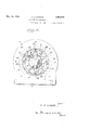
Figure l is a transverse central section through the apparatus on the line 1-1Iof 1930. Serial No. 443,517.
Figure 2, with parts in elevation, showing the pawls in position to prevent reverse rotation of the shaft. i
Figure 2 is in part a section on the line 22of Figure 1 with parts in elevation and in part a side elevation. v
Fig. 3 is a view similar to Fig. 1, but with the pawls inposition to permit for ward rotation of the, shaft. i
- The apparatus comprises a hollow bearing block or housing 1, which, for con venien'ce in manufacture and assembly, may be made inrtwo identical sections formed with laterally 'and outwardly extending flanges 2 by which the two sections may be clamped together by bolts 3. Each section is provided with a base 4 by which the bearing block may be secured to any suitable supporting means.
The shaft v5 is journaled in the bearing block in any convenient manner, such as by rollers 6 arranged between suitable bearing Surfaces orrunways. The outer roller runways are formed by-steel rings 7 a held in place by rings 7, bolted to the ends of the bearing block. The inner roller runways 8a abut against the ends of a steel collar 8, which is non-rota-tably secured to the shaft 5 by a key 9. The rings 7 are to advantage formed with a radially inwardly extending grooved flange, inthe grooves of which felt or other packing may be inserted to contact with the shaft 5 for the dual purpose of ex eluding dirt and retaining oil. I
The peripheral interior surface of the hearing block is formed with a series of inwardly p'rojectingteeth or serrations 10 to be engaged by pawls 11. The latter are mounted so that they are moved in and out of engagement with the serrations without the aid of springs or the like. Further, the pawls are so designed and mounted that when the shaft is turning in the direction of the arrow, shown in Fig. 1, the pawls are entirely out of contact with the serrations and there is no movement of any of the parts other than a smooth noiseless rota tion of the moving parts about the axis of the shaft. Further, it is advantageous to use a plurality" of pawls symmetrically disposed about the shaft to give balance to the apparatus. Theseadvantageous results may be obtained in various ways, one convenient method involving mounting the pawls on a squirrel-cage formed of two rings but free to rotate with respect to the bearing block.
The friction between the edge of the rings 12 andthe antifrictionmetal strips 14 is greater than the frictionfbe'tween the pawls and the pins 13 on which they are mounted.
Hence, by providing a loose'connection between the shaft and the pawls, the turning of the shaft will first cause the pawls 11 to turn on their pins as far as possible and not until that has been accomplished will the squirrel cage be moved.
The pawls and shaft 5 maybe loosely connected in Various ways. One convenient method is by means of lugs 15 projecting outwardly from the collar 8 and extending into recesses 16 in the pawls. These recesses are wider than the projections to allow the desired relative movement between such projections and the adjacent pawls. v
The pawls are so designed and mounted that movement of the shaft in one direction only (i; e. in the opposite direction to that indicated by the arrow in Fig. 3) causes the pawls to engage the serrationslO. This is conveniently accomplishedby providing a projecting tip 17 on one arm .of'each pawl which engages the serrations 10 (see Fig. 1 when the shaft 5 attempts to rotate in the direction opposite to that indicated by the arrow in Fig. 3 to prevent such rotation,
' eachpawl being-so mounted that when shaft 5 rotates in the direction of the arrow in Fig. 3, shoulder 16 of each pawl engages collar 8 to act as a stop to restrain outward movement of the other arm of the pawl at a point early enough to prevent the-end of such other arm of the pawl coming into enf gageinent with the serrations 10 (see Fig. 3). Adouble-ended, centrally pivoted pawl, as shown, has the advantage that it enables the pawl to be balancedagainst centrifugal force, which would otherwise force the tip 17 outwardly against the serrations and thereby cause friction, wear and. noise, when the shaft is turning in the direction of the arrow in Fig. 1. g ,Preferably the interior of the bearing is filled with oil to ensure thorough lubrication and reduce wear- While the back stop may advantageously be combined with and made a part of one of the shaft bearings, such combination is projections.
not essential and the back stop may be arranged in a housing supported by the shaft, although provided with means for preventing rotation of the housing with the shaft.
In operation, if the shaft is turned in the direction of the arrow shown in Fig. 3, the projections 15 engage the shoulders 16 of thelrecesses 16 of the pawls, and, since the friction of the pawls on their pivots 13 is less" than the friction of the squirrel cage with respect to thebabbitt strips 14, cause the pawls to turn about their pivotal axes so as to draw the projecting ends or tips 17 of the latter out of engagement with the teeth or serrations 14-. This turning movement continues until the other shoulders 16' of the recesses in the pawls contact with the collar 8. This occurs before the ends of the pawls opposite the tips 17 contact with the teeth 10.- As soon as the pawls have com pleted this movement, further rotation of the shaft produces rotation of the squirrel cage.
When the shaft is turned in the opposite direction (see Fig. 1) the pawls are rotated about their pivotal axes in the opposite direction so as to bring the tips 17 in engagement with the teeth 10, thereby preventing any further rotation of the shaft in that direction.
What is claimed is: s
1. A combined back-stop and bearing comprising a shaft, a hollow bearing therefor, having on its interior face internally directed projections and a pawl operatively connected to said shaft adapted by radial movement and independently of centrifugal forceto engage said projections in only one direction of rotation of said shaft, said pawl being held out of engagement with said projections when the shaft rotates in the other direction. I v V '2. A back-stop comprising a rotatable member, a stationary annular member surrounding the first member, inwardly extending projections on the second member, a ring rotatably mounted within the second member and in frictional engagement therewith,
pawl and said rotatable member to allow the frictional drag of said ring to turn saidpawl about itsJpivot, rotation of said rotatable member in .one direction moving the pawl into. engagement with one of said 3.,Aback-stop as in claim 2 in which said operative: connection comprises a recess in said pawl on the side opposite said rotatable member and a projection on said rotatable member entering and loosely engaging the walls-of said recess.
4:. A back-stopas in claim 2 in which a band of antifriction metal is mounted in engagement with said projections opposite to and in frictional engagement with the periphery of said ring.
5. A back-stop comprising a rotatable member, a stationary annular member surrounding the first member, inwardly extending projections on the second member, a ring rotatably mounted within the second member and in frictional engagement therewith, a pawl pivotally mounted intermediate its ends on said ring, a projection on the first member adapted to engage a recess in said pawl adjacent the pivot of the latter to turn the pawl in either direction according to the direction of rotation of the first member, movement of the pawl in one direction bringing one end of the pawl in locking engagement with one of said projections and means for limiting movement of the pawl in the opposite direction sufliciently to prevent the other end of the pawl engaging said projections.
6. A back-stop comprising a rotatable member, a stationary annular member sur rounding the first member, inwardly extending projections on the second member, a ring rotatably mounted within the second memher and in frictional engagement therewith, and a pawl pivotally mounted on said ring, the pivot point of said pawl being so located that the centrifugal force produced by the rotation of said ring has substantially no turning effect on the pawl, movement of the first member in one direction moving the pawl into engagement with one of said projections.
7. A back-stop as in claim 2 in which the pivot point of said pawl is so located that the centrifugal force produced by the rotation of said ring has substantially no turning effect on the pawl.
8. In a device of the character described, a rotatable member, an annular member surrounding the rotatable member and provided with a plurality of inwardly extending projections, a third member rotatably mounted within the second member and in frictional engagement therewith, a pawl pivotally mounted on said third member and a movable operative connection between the pawl and said rotatable member to allow the frictional drag of said third member to turn said pawl about its pivot, rotation of said rotatable member in one direction moving the pawl into engagement with one of said projections to prevent relative rotation of said rotatable member and said second member, rotation of said rotatable memher in the other direction moving the pawl out of engagement with said projections and maintaining the pawl in disengaged position during such rotation.
In testimony whereof I hereunto afix my signature.
EUGENE E. LANDAHL.
Priority Applications (1)
| Application Number | Priority Date | Filing Date | Title |
|---|---|---|---|
| US443517A US1908905A (en) | 1930-04-11 | 1930-04-11 | Backstop for machinery |
Applications Claiming Priority (1)
| Application Number | Priority Date | Filing Date | Title |
|---|---|---|---|
| US443517A US1908905A (en) | 1930-04-11 | 1930-04-11 | Backstop for machinery |
Publications (1)
| Publication Number | Publication Date |
|---|---|
| US1908905A true US1908905A (en) | 1933-05-16 |
Family
ID=23761099
Family Applications (1)
| Application Number | Title | Priority Date | Filing Date |
|---|---|---|---|
| US443517A Expired - Lifetime US1908905A (en) | 1930-04-11 | 1930-04-11 | Backstop for machinery |
Country Status (1)
| Country | Link |
|---|---|
| US (1) | US1908905A (en) |
Cited By (8)
| Publication number | Priority date | Publication date | Assignee | Title |
|---|---|---|---|---|
| US3332720A (en) * | 1966-02-01 | 1967-07-25 | Melvin O Hansen | Retractable, stowable and yieldable to normal force but automatically restraining tonon-normal force seat belt mechanism |
| US3354993A (en) * | 1964-06-09 | 1967-11-28 | Philips Corp | One way brake for a self-starting synchronous motor |
| US3774477A (en) * | 1971-12-30 | 1973-11-27 | D Murphy | Gear motor |
| US3921930A (en) * | 1972-03-24 | 1975-11-25 | Foehl Artur | Winding-up device with automatic lock initiated by friction for a safety belt |
| US4230414A (en) * | 1977-10-18 | 1980-10-28 | Uop Inc. | Ratchet-action hinge device |
| US4410072A (en) * | 1981-08-14 | 1983-10-18 | Westinghouse Electric Corp. | Gravity controlled anti-reverse rotation device |
| US4548304A (en) * | 1981-11-17 | 1985-10-22 | Canon Kabushiki Kaisha | One-way clutch and winding and rewinding device for camera using the same |
| WO1997016660A1 (en) * | 1995-11-01 | 1997-05-09 | Abb Kraft A/S | Power transfer device |
-
1930
- 1930-04-11 US US443517A patent/US1908905A/en not_active Expired - Lifetime
Cited By (8)
| Publication number | Priority date | Publication date | Assignee | Title |
|---|---|---|---|---|
| US3354993A (en) * | 1964-06-09 | 1967-11-28 | Philips Corp | One way brake for a self-starting synchronous motor |
| US3332720A (en) * | 1966-02-01 | 1967-07-25 | Melvin O Hansen | Retractable, stowable and yieldable to normal force but automatically restraining tonon-normal force seat belt mechanism |
| US3774477A (en) * | 1971-12-30 | 1973-11-27 | D Murphy | Gear motor |
| US3921930A (en) * | 1972-03-24 | 1975-11-25 | Foehl Artur | Winding-up device with automatic lock initiated by friction for a safety belt |
| US4230414A (en) * | 1977-10-18 | 1980-10-28 | Uop Inc. | Ratchet-action hinge device |
| US4410072A (en) * | 1981-08-14 | 1983-10-18 | Westinghouse Electric Corp. | Gravity controlled anti-reverse rotation device |
| US4548304A (en) * | 1981-11-17 | 1985-10-22 | Canon Kabushiki Kaisha | One-way clutch and winding and rewinding device for camera using the same |
| WO1997016660A1 (en) * | 1995-11-01 | 1997-05-09 | Abb Kraft A/S | Power transfer device |
Similar Documents
| Publication | Publication Date | Title |
|---|---|---|
| US3107955A (en) | Bearing | |
| US1737997A (en) | Means for the transmission of power | |
| US1908905A (en) | Backstop for machinery | |
| US2569533A (en) | Differential | |
| US3497046A (en) | Rotary seal for clutch and brake members having relative rotation and reciprocation | |
| US1434970A (en) | Clutch | |
| US2076239A (en) | Trolley roller | |
| US1781083A (en) | Power-driving unit | |
| US1831577A (en) | Speed change mechanism | |
| US1453548A (en) | Overrunning clutch | |
| US2622946A (en) | Retaining means for idler units | |
| US1972355A (en) | Roller bearing | |
| US2155657A (en) | Thrust bearing | |
| US2055081A (en) | Aircraft propelling mechanism | |
| US1687756A (en) | Roller bearing | |
| US2155766A (en) | Constant-fit bearing | |
| US1291654A (en) | Automatically-adjusting speed or revolution change gear. | |
| US2049118A (en) | Wheel mounting for rail vehicles | |
| US1634507A (en) | Ball transmission | |
| US1139192A (en) | Roller-bearing. | |
| US1674979A (en) | Driving mechanism | |
| US2231832A (en) | Transmission | |
| US1744393A (en) | Take-up for multiple antifriction bearings | |
| US1417072A (en) | Bearing | |
| US879679A (en) | Hoisting device. |