US1908880A - Alternating current electric motor for phonographs and the like - Google Patents
Alternating current electric motor for phonographs and the like Download PDFInfo
- Publication number
- US1908880A US1908880A US411591A US41159129A US1908880A US 1908880 A US1908880 A US 1908880A US 411591 A US411591 A US 411591A US 41159129 A US41159129 A US 41159129A US 1908880 A US1908880 A US 1908880A
- Authority
- US
- United States
- Prior art keywords
- stator
- magnetic field
- rotor
- phonographs
- torque
- Prior art date
- Legal status (The legal status is an assumption and is not a legal conclusion. Google has not performed a legal analysis and makes no representation as to the accuracy of the status listed.)
- Expired - Lifetime
Links
Images


Classifications
-
- H—ELECTRICITY
- H02—GENERATION; CONVERSION OR DISTRIBUTION OF ELECTRIC POWER
- H02K—DYNAMO-ELECTRIC MACHINES
- H02K19/00—Synchronous motors or generators
- H02K19/02—Synchronous motors
- H02K19/14—Synchronous motors having additional short-circuited windings for starting as asynchronous motors
Definitions
- the present invention has for its object to provide an alternating current electric inc tor suitable for driving phonographs or similar purposes.
- the motor drives directly the a table carrying the record disc (or equivalent member) without the necessity of providing it with a friction governor of the usual type, r it comprises no commutator and its construc- F tion is sturdy and economical.
- Figures 1 and 2 show one emhodiment oi the invention
- Fig. 1a shows a sectional view of the stators on the line 1a-lo of Fig. 2
- Fig. 2a shows the characteristic curve of the gower of the device as a function of speed
- ig. 3 shows a modified form wherein the stator laminations are perpendicular to the rotor axis
- Fig. l shows a modified form wherein the rotor is c lindrical and the stator is adjacentthe cylin rical surface of the rotor
- Fig 5 shows a modified form wherein the induction motor side of the rotor is slotted and wound
- Fig. 6 shows a modification wherein the rotor is slotted and wound and both stators are on the same side of the retor
- Fig. 7 shows a method of connecting the windings of the two stators in series
- the rotor comprises a disc 4 of a metal, such as copper or aluminum, which is a good con' cluster and ,a plate 5 of ma netic material.
- the disc 4 is-subjectedto t e inductive eifect of a stator'l, formed of laminated metal andprovided with slots'2; this stator is arranged close to the periphery of the rotor, as may be seenifrom Fig. 1a, which shows a a section taken on the line 1a1a of Fig. 2. In order to explain the arrangement there have been shown in Fig. 2, four slots of.
- the record the slip is 50% two-phase windings suppliedhy common single phase source by connecting conductors 21 and 22, or 23 and 24, respectively the two wires 25 and 26 supplied by the single phase source 27 and by inserting a phase shifter 28 which may consist of impedances in the conductor 21.
- the change oil the respective phase of the currents in the two windings can furthermore he effected by means of any other known device.
- the lower ot'the plate 5 is provided, near its ery, with teeth d which move past teeth m 7 of a second stator 2, comprising a laminated metal core and a winding 9 which is plied from the same source of current 27 as the windings arranged on the stator Tl Fey means of the conductors 29 and 30, connect ed respectively to the wires 25 and 26.
- An alternator of the so called varialole reluctance type is thus obtained, which exerts a torque on the disc 4i which is additional to,
- lay-suitably prodisc may he maintained at this synchronous speed, that is to say at a substantially constant speed, the frequency of modern alternating current mains onl varying within very small limits.
- the speed or synchronism of the alternator must be substantially below the speed at which thetorque exerted by the stator 1, 2 on the disc t vanishes.
- the system 1, 2, 4 really forms a low powered in- 05' duction motor, rotating atvery low speed and having a progressive magnetic field and a torque'substantially proportional to the its output is thus'at a maximum when slip;
- the torque produced by this assembly when the rotor is stationary is sufiicient to overcome the magnetic attraction between the teeth 6 and the teeth 7, when the winding 9 is excited.
- the maximum retarding torque produced by this assembly remains sufiiciently higher than the torque produced by the stator 1 and thus effects an automatic synchronizing when the normal speed is reached.
- the assembly 6, 7, 8, 9 produces a pulsating magnetic field.
- the rotor 3 may thus be started by the mere closing'of a switch 31 which controls the circuits of the windings 2 and 9, without the operator having to perform any further operation.
- the condition for maintaining synchronism of the "motor unit by the synchronous motor is that the torque of the synchronous motor shouldexceed at normal speed the torque of the induction motor. It will be realized that if the normal speed is 50% of the synchronous speed of the induction motor, a value corresponding to the maximum of the power parabola, the torque of the synchronous motor should exceed by 50% the starting torque OC ofv the induction motor. But as calculations will show, the starting torque and the torque due to'the magnetic attraction of the teeth 6 and 7 is double the a torque of the synchronous machine at syn- 1 of the motor.
- the synchronous motor can be arranged in such a manner that its torque will be less than 50% of the starting torque but greater than the torque of the induction motor at normal speed.
- the slip of 30% in normal operation represented by AD on Fig. 2a appears to suit in the majority of cases, and again it corresponds to a very satisfying utilization of the assembly 1, 2, 4, whose power AG attains again 84% of the maximum power EH, the torque AB of the synchronous motor exceeding the torque AF of'the induction motor but being less than 50% of the starting torque OC.
- Figure 3 shows in section (similar to 1) a modified arrangement in which the' planes of the laminae forming the stator 8 are parallel to the plate 5; the teeth 6 are formed in the actual periphery of the said plate which thus takes the form of a spur wheel.
- the remainder of the apparatus is as shown in Figs. 1 and 2,-the same references indicating similar parts.
- the same ap lies to the modification shown in Fig. 4.
- w ich only differs essentiall from the arrangement placed by a squirrel-cage windlng 10 (or.
- the number of slotsholdin the said windings may correspond in num er to those on the stator 8 and are preferably so arranged that the axis of each of these slots coincides with the axis of one of the teeth 6 (as shown in the figure) maximum utilization is thus made of the iron core of the rotor.
- the stator 8 may Ee stator 1, each of the stators occupying a portion only of the total periphery as shown in Fig. 6; the stator 8 thus acts on the teeth 11 separating the conductors 10 of the squirrelcage.
- the latter weakening the variations of reluctance thus producedit may be advantageous to allow magnetic leakage to occur, for example, by arrangin the conducarranged on the same side of the rotor as the tors 10 at the bottom of sufficient y deep slots.
- stator 8 which ensures nchronous operation is shown in the form 0 an E, the central armof which is provided at its extremity with two teeth 7; the arrangement is particularly advantageous both from the point of view of elliciency and of construction.
- a stator wound to produce a progressive magnetic field a separate stator wound to produce a pulsating magnetic field, a common rotor rotating in-the fields of said two stators and having salient; poles cooperating with said pulsatin magnetic field,'and means forsupplying te stator windings with alternating 2.
- a stator wound to produce a progressive magnetic field a separate stator wound to produce a pulsating magnetic field, a common'rotor having salient poles cooperating with said pulsating magnetic'field, a part of the pe riphery of said common rotor'being acted upon simultaneously by .the field of each stator, and means for supplying the'stator,
- a stator wound to produce a progressive magnetic field a separate stator wound to produce a pulsating magnetic field, a common rotor rotating in-the fields of said two stators 05 and having salient poles cooperating with said pulsating magnetic field, and means -for supplying said stators with alternating current, said two stators and said rotor bein constructed so that the synchronous spec of said pulsating magnetic field is equal to I a proximately seventy percent of the syncnronous speed of said progressive magnetic field.
- stator wound to produce a progressive mag.- netic field, a separate stator wound to produce a pulsating magnetic field, a common rotor rotating in the fields of said two stators and having salient poles cooperating with said pulsating magnetic field, said rotor comprising a layer oi material of high electrical con uctivity coacting with said progressive magnetic field and another layer of material of high magnetic permeability coacting with said pulsating magnetic field,
- said la er of material of high magnetic permea ility being provided with peripheral slots, conductors oi high electrical conductivity carried in said slots, and means for exciting said stators with alternating current for establishing said progressive magnetic field for driving said rotor.
- a stator wound to produce a progressive magnetic field a separate stator wound to produce a pulsating magnetic field
- a common rotor rotating in the fields of said two stators and provided on one face thereof substantially perpendicular to its axis ofrotation with peripheral teeth and intermediate slots carrying conductors of high electrical conductivity, both of said stators being positioned on the slotted side of said rotor for presentation in magnetic relation thereto and for cooperation between said pulsating magnetic field and the teeth and slots of said rotor.
- a combined motor unit comprising a stator wound to produce a progressive magnetic field and a stator wound to produce a pulsating magnetic field, a composite rotor common to said stators comprising a layer of material of high electrical conductivity and a layer of material of high magnetic permeability superposed on said first mentioned layer, said layer of material of high magnetic permeability being provided with salient poles cooperating with said pulsating field.
- a combined motor unit comprising a stator wound to produce a progressive magnetic field and a stator wound to produce a pulsating magnetic field,- a composite rotor trical conductivity being provided with slots positioned for presentation to said stator wound to produce a progressive magnetic field, said slots in said material of high elec trical conductivity being provided with a winding cooperatlng with said progressive magnetic field.
Landscapes
- Engineering & Computer Science (AREA)
- Power Engineering (AREA)
- Synchronous Machinery (AREA)
- Induction Machinery (AREA)
Description
J. BETHENOD May 16, 1933.
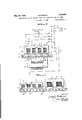
ALTERNATING CURRENT ELECTRIC MOTOR FOR PHONOGRAPHS AND THE LIKE Filed Dec. 4, 1929 3 Sheets-Sheet 1 (Illllllllllz M W 5 MW M U o w w 5 M 3 vM .A w Qw v W mm a M my a m m H W; .M w 1 .Ja r .m *m w 3;? v I J. W 3 Z I L, 7 7
May 16, 1933. J. BETHENOD ALTERNATING CURRENT ELECTRIC MOTOR FOR PHONOGRAPHS AND THE LIKE Filed Dec. 4, 1929 SSheets-Sheet 2 Pase(6/zfler /0 3 INVENTOR.
JW/My Vz bxzfifm),
WTTORNEYZ y 5 1933- J. BETHENOD 1,908,880
ALTBRNATING CURRENT ELECTRIC MOTOR FOR PHONOGRAPHS AND THE LIKE Filed Dec. 4, 1929 3 Sheets-Sheet 3 III Patented May 16, 1933'.-
UNITED STATES Persu- JOBEPH EIETHENDD, @3 il /A318, FRANCE Application filed December 4, 1926, Berle. Ho. eraser, and in France Eleceaaher d, was.
The present invention has for its object to provide an alternating current electric inc tor suitable for driving phonographs or similar purposes. The motor drives directly the a table carrying the record disc (or equivalent member) without the necessity of providing it with a friction governor of the usual type, r it comprises no commutator and its construc- F tion is sturdy and economical.
,Figures 1 and 2 show one emhodiment oi the invention; Fig. 1a shows a sectional view of the stators on the line 1a-lo of Fig. 2; Fig. 2a shows the characteristic curve of the gower of the device as a function of speed; ig. 3 shows a modified form wherein the stator laminations are perpendicular to the rotor axis; Fig. l shows a modified form wherein the rotor is c lindrical and the stator is adjacentthe cylin rical surface of the rotor; Fig 5 shows a modified form wherein the induction motor side of the rotor is slotted and wound; Fig. 6 shows a modification wherein the rotor is slotted and wound and both stators are on the same side of the retor; and Fig. 7 shows a method of connecting the windings of the two stators in series,
In the arrangement shown in Figs. l and 2 the rotor member of the motor is shown at 3 (Fig. 1) and is given the form of a wheel:
the hub 12 of which is secured on a vertical shaft 13 which is held inhearings 1i and 15 and carries at its upper end the turn tahle 16 on which the record disc is placed. The rotor comprises a disc 4 of a metal, such as copper or aluminum, which is a good con' cluster and ,a plate 5 of ma netic material. The disc 4 is-subjectedto t e inductive eifect of a stator'l, formed of laminated metal andprovided with slots'2; this stator is arranged close to the periphery of the rotor, as may be seenifrom Fig. 1a, which shows a a section taken on the line 1a1a of Fig. 2. In order to explain the arrangement there have been shown in Fig. 2, four slots of.
which two, 17 and 19, carry the active conductors belonging to a. first coil, and a secand coil corresponds to slots 18 and 20. The first coil is supplied through the conductors 21 and 22, the second through conductors 23 and 24. There'is obtained a system of or opposed to, that exerted by the system 1, 2
portioning the various elements, the record the slip is 50% two-phase windings suppliedhy common single phase source by connecting conductors 21 and 22, or 23 and 24, respectively the two wires 25 and 26 supplied by the single phase source 27 and by inserting a phase shifter 28 which may consist of impedances in the conductor 21. The change oil the respective phase of the currents in the two windings can furthermore he effected by means of any other known device.
The currents induced in the disc d hy this system cause rotation of the rotor ii, the plate 5 closing the magnetic circuit oi he system. lo prevent a substantial. varin oi the speed rotation w h voriati potential of the source o2? cur ent or ations in the couple produced the tri 1 or" the pick up, or the like, the lower ot'the plate 5 is provided, near its ery, with teeth d which move past teeth m 7 of a second stator 2, comprising a laminated metal core and a winding 9 which is plied from the same source of current 27 as the windings arranged on the stator Tl Fey means of the conductors 29 and 30, connect ed respectively to the wires 25 and 26. An alternator of the so called varialole reluctance type is thus obtained, which exerts a torque on the disc 4i which is additional to,
according as the speed of the rotor 3 tends to he higher or lower than the speed of synchronism oi the said alterhator.
It will thus be seen that lay-suitably prodisc may he maintained at this synchronous speed, that is to say at a substantially constant speed, the frequency of modern alternating current mains onl varying within very small limits. To enab e the device to opcrate in this manner, the speed or synchronism of the alternator must be substantially below the speed at which thetorque exerted by the stator 1, 2 on the disc t vanishes. The system 1, 2, 4 really forms a low powered in- 05' duction motor, rotating atvery low speed and having a progressive magnetic field and a torque'substantially proportional to the its output is thus'at a maximum when slip;
and it would be of advantage 100 speed of the induction motor.
from this point. of view to so proportion the elements of the motor that this would correspond to the normal speed; however, experience shows that if the normal s eed is fixed in this manner the torque exerte by the stator 1 when the rotor is stationary may be insuflicient for startin if the winding 9 is also excited. It is t erefore necessary to close the circuit of this winding 9 only after rotation has begun if a slip of 50% is employed. This necessity may be inconvenient and in any case leads to certain complications in the switching arrangements. It becomes unnecessary if a normal speed is chosen which corresponds to a smaller slip of the disc 4 relative to the displacement of the magnetic field produced by the assembly 1, 2. It may be shown that under these conditions the torque produced by this assembly when the rotor is stationary is sufiicient to overcome the magnetic attraction between the teeth 6 and the teeth 7, when the winding 9 is excited. Moreover, it may be shown that when the speed of synchronism of the alternator formed by the assembly 6, 7, 8, 9 is reached, the maximum retarding torque produced by this assembly remains sufiiciently higher than the torque produced by the stator 1 and thus effects an automatic synchronizing when the normal speed is reached. The assembly 6, 7, 8, 9 produces a pulsating magnetic field. The rotor 3 may thus be started by the mere closing'of a switch 31 which controls the circuits of the windings 2 and 9, without the operator having to perform any further operation.
The considerations set forth will be understood by examining the diagram of Fig. 2a in which there are shown as abscissas the speeds, and as ordinates the torques, and finally the powers. GA is the normal speed corresponding to synchronism of the syn-' chronous motor. OD is the synchronous H The line CD represents the torque of the induction motor and the parabola OED represents the power furnished by the whole assembly. The torque of the synchronous motor is represented by the ordinate AB; it is zero for every speed except synchronism.
The condition for maintaining synchronism of the "motor unit by the synchronous motor is that the torque of the synchronous motor shouldexceed at normal speed the torque of the induction motor. It will be realized that if the normal speed is 50% of the synchronous speed of the induction motor, a value corresponding to the maximum of the power parabola, the torque of the synchronous motor should exceed by 50% the starting torque OC ofv the induction motor. But as calculations will show, the starting torque and the torque due to'the magnetic attraction of the teeth 6 and 7 is double the a torque of the synchronous machine at syn- 1 of the motor. By choosing the normal spee to exceed 50% of the synchronous speed of the induction motor, the synchronous motor can be arranged in such a manner that its torque will be less than 50% of the starting torque but greater than the torque of the induction motor at normal speed.
Taking into consideration the reasons set forth, the slip of 30% in normal operation, represented by AD on Fig. 2a appears to suit in the majority of cases, and again it corresponds to a very satisfying utilization of the assembly 1, 2, 4, whose power AG attains again 84% of the maximum power EH, the torque AB of the synchronous motor exceeding the torque AF of'the induction motor but being less than 50% of the starting torque OC.
Figure 3 shows in section (similar to 1) a modified arrangement in which the' planes of the laminae forming the stator 8 are parallel to the plate 5; the teeth 6 are formed in the actual periphery of the said plate which thus takes the form of a spur wheel. The remainder of the apparatus is as shown in Figs. 1 and 2,-the same references indicating similar parts. The same ap lies to the modification shown in Fig. 4. w ich only differs essentiall from the arrangement placed by a squirrel-cage windlng 10 (or.
equivalent system). In this case the number of slotsholdin the said windings may correspond in num er to those on the stator 8 and are preferably so arranged that the axis of each of these slots coincides with the axis of one of the teeth 6 (as shown in the figure) maximum utilization is thus made of the iron core of the rotor. With the squirrel-ca e arrangement of Fig. 5, the stator 8 may Ee stator 1, each of the stators occupying a portion only of the total periphery as shown in Fig. 6; the stator 8 thus acts on the teeth 11 separating the conductors 10 of the squirrelcage. To prevent, the latter weakening the variations of reluctance thus producedit may be advantageous to allow magnetic leakage to occur, for example, by arrangin the conducarranged on the same side of the rotor as the tors 10 at the bottom of sufficient y deep slots.
Figs. 5 and 6, the stator 8 which ensures nchronous operation is shown in the form 0 an E, the central armof which is provided at its extremity with two teeth 7; the arrangement is particularly advantageous both from the point of view of elliciency and of construction.
It should be noted that all the embodiments above described are given by way of example only and that further variations are postor and not being the one which supplies conductor. 26'; the series method of connection allows wire of a relatively larger gauge to be used, which is clearly o importance in the construction of a low powered device. Moreover, with the series connection it is only neccurrent.
essary to momentarily short circuit the winding 9 by means of interrupter 32 to increase the couple exerted bythe stator l, as a higher potential will then be 'ap lied to the winding 2; this may be of use tor accelerating the starting in certain special cases.
I claim:
1. In a system for driving phonographs, a stator wound to produce a progressive magnetic field, a separate stator wound to produce a pulsating magnetic field, a common rotor rotating in-the fields of said two stators and having salient; poles cooperating with said pulsatin magnetic field,'and means forsupplying te stator windings with alternating 2. In a system for driving phonographs, a stator wound to produce a progressive mag: netic field, a separate stator Wound to produce a pulsating magnetic field,.a common rotor in the form of a disc rotating in the fields of said two stators and having salient poles cooperating'with said pulsating magnetic field, and means for supplying said stators with alternating current.
3. In a system for driving phonographs, a stator wound to produce a progressive magnetic field, a separate stator wound to produce a pulsating magnetic field, a common'rotor having salient poles cooperating with said pulsating magnetic'field, a part of the pe riphery of said common rotor'being acted upon simultaneously by .the field of each stator, and means for supplying the'stator,
windings with alternating current. a
4. In a system for driving phonographs, a stator wound to produce a progressive magnetic field, a separate stator wound to produce a pulsating magnetic field, a common rotor rotating in-the fields of said two stators 05 and having salient poles cooperating with said pulsating magnetic field, and means -for supplying said stators with alternating current, said two stators and said rotor bein constructed so that the synchronous spec of said pulsating magnetic field is equal to I a proximately seventy percent of the syncnronous speed of said progressive magnetic field.
5. In a system for driving phonographs,
stator wound to produce a progressive mag.- netic field, a separate stator wound to produce a pulsating magnetic field, a common rotor rotating in the fields of said two stators and having salient poles cooperating with said pulsating magnetic field, said rotor comprising a layer oi material of high electrical con uctivity coacting with said progressive magnetic field and another layer of material of high magnetic permeability coacting with said pulsating magnetic field,
said la er of material of high magnetic permea ility being provided with peripheral slots, conductors oi high electrical conductivity carried in said slots, and means for exciting said stators with alternating current for establishing said progressive magnetic field for driving said rotor.
6. in a motor unit, a stator wound to produce a progressive magnetic field, a separate stator wound to produce a pulsating magnetic field, a common rotor rotating in the fields of said two stators and provided on one face thereof substantially perpendicular to its axis ofrotation with peripheral teeth and intermediate slots carrying conductors of high electrical conductivity, both of said stators being positioned on the slotted side of said rotor for presentation in magnetic relation thereto and for cooperation between said pulsating magnetic field and the teeth and slots of said rotor.
7. In a combined motor unit comprising a stator wound to produce a progressive magnetic field and a stator wound to produce a pulsating magnetic field, a composite rotor common to said stators comprising a layer of material of high electrical conductivity and a layer of material of high magnetic permeability superposed on said first mentioned layer, said layer of material of high magnetic permeability being provided with salient poles cooperating with said pulsating field.
8. In a combined motor unit comprising a stator wound to produce a progressive magnetic field and a stator wound to produce a pulsating magnetic field,- a composite rotor trical conductivity being provided with slots positioned for presentation to said stator wound to produce a progressive magnetic field, said slots in said material of high elec trical conductivity being provided with a winding cooperatlng with said progressive magnetic field.
JOSEPH BETHEN OD.
Applications Claiming Priority (3)
| Application Number | Priority Date | Filing Date | Title |
|---|---|---|---|
| FR1908880X | 1928-12-05 | ||
| FR342427X | 1928-12-08 | ||
| FR566674X | 1928-12-08 |
Publications (1)
| Publication Number | Publication Date |
|---|---|
| US1908880A true US1908880A (en) | 1933-05-16 |
Family
ID=27249029
Family Applications (1)
| Application Number | Title | Priority Date | Filing Date |
|---|---|---|---|
| US411591A Expired - Lifetime US1908880A (en) | 1928-12-05 | 1929-12-04 | Alternating current electric motor for phonographs and the like |
Country Status (2)
| Country | Link |
|---|---|
| US (1) | US1908880A (en) |
| DE (1) | DE566674C (en) |
Cited By (2)
| Publication number | Priority date | Publication date | Assignee | Title |
|---|---|---|---|---|
| WO1993015513A1 (en) * | 1992-01-31 | 1993-08-05 | Flynn Charles J | Permanent magnet control means |
| US20070018520A1 (en) * | 2005-07-21 | 2007-01-25 | Nissan Motor Co., Ltd. | Motor/generator to reduce cogging torque |
-
1929
- 1929-11-30 DE DEB147011D patent/DE566674C/en not_active Expired
- 1929-12-04 US US411591A patent/US1908880A/en not_active Expired - Lifetime
Cited By (5)
| Publication number | Priority date | Publication date | Assignee | Title |
|---|---|---|---|---|
| WO1993015513A1 (en) * | 1992-01-31 | 1993-08-05 | Flynn Charles J | Permanent magnet control means |
| US5254925A (en) * | 1992-01-31 | 1993-10-19 | Flynn Bros., Inc. | Permanent magnet control means |
| US20070018520A1 (en) * | 2005-07-21 | 2007-01-25 | Nissan Motor Co., Ltd. | Motor/generator to reduce cogging torque |
| US7595575B2 (en) * | 2005-07-21 | 2009-09-29 | Nissan Motor Co., Ltd. | Motor/generator to reduce cogging torque |
| CN100578892C (en) * | 2005-07-21 | 2010-01-06 | 日产自动车株式会社 | motor generator |
Also Published As
| Publication number | Publication date |
|---|---|
| DE566674C (en) | 1932-12-28 |
Similar Documents
| Publication | Publication Date | Title |
|---|---|---|
| US3210644A (en) | Dynamo electric machine | |
| US1908880A (en) | Alternating current electric motor for phonographs and the like | |
| US2310874A (en) | Variable speed motor | |
| US2333538A (en) | Induction motor with open-slot rotor windings | |
| US3573578A (en) | Electric machine arrangements including electric rotating machines | |
| US2479329A (en) | Single-phase electric motor | |
| US2570894A (en) | Multispeed motor | |
| US2796580A (en) | Dynamo-electric machines | |
| US2054678A (en) | Direct-current motor-inductor alternator | |
| US3541410A (en) | Excitation apparatus for synchronous rotating machinery | |
| US1300308A (en) | Electrical converter. | |
| US1479463A (en) | Electric brake | |
| US1872371A (en) | Alternating current motor | |
| US2287603A (en) | Frequency changer set | |
| US1239979A (en) | Alternating-current motor. | |
| US1709120A (en) | Combination of induction machine and commutator machine | |
| US1784235A (en) | Induction synchronous motor system | |
| US1218747A (en) | Multispeed induction-motor. | |
| US1675677A (en) | Alternating-current motor | |
| US2642555A (en) | Adjustable speed induction motor | |
| US1187180A (en) | Means for improving the power factor of induction-machines. | |
| US2462184A (en) | Quiet single-phase motor | |
| US1336566A (en) | Speed-control system for induction-motors | |
| US1637040A (en) | Self-excited induction motor | |
| US1454872A (en) | Commutator repulsion induction motor |