US1908801A - Odometer - Google Patents
Odometer Download PDFInfo
- Publication number
- US1908801A US1908801A US267167A US26716728A US1908801A US 1908801 A US1908801 A US 1908801A US 267167 A US267167 A US 267167A US 26716728 A US26716728 A US 26716728A US 1908801 A US1908801 A US 1908801A
- Authority
- US
- United States
- Prior art keywords
- odometer
- shaft
- gear
- eccentric
- hub
- Prior art date
- Legal status (The legal status is an assumption and is not a legal conclusion. Google has not performed a legal analysis and makes no representation as to the accuracy of the status listed.)
- Expired - Lifetime
Links
Images

Classifications
-
- G—PHYSICS
- G06—COMPUTING; CALCULATING OR COUNTING
- G06M—COUNTING MECHANISMS; COUNTING OF OBJECTS NOT OTHERWISE PROVIDED FOR
- G06M1/00—Design features of general application
- G06M1/04—Design features of general application for driving the stage of lowest order
- G06M1/06—Design features of general application for driving the stage of lowest order producing continuous revolution of the stage, e.g. with gear train
- G06M1/064—Design features of general application for driving the stage of lowest order producing continuous revolution of the stage, e.g. with gear train for dial, pointer, or similar type indicating means
Landscapes
- Physics & Mathematics (AREA)
- General Physics & Mathematics (AREA)
- Engineering & Computer Science (AREA)
- Theoretical Computer Science (AREA)
- Measurement Of Distances Traversed On The Ground (AREA)
- Gear Transmission (AREA)
Description
May 16, 1933- c. H. VEEDER 1,908,801
ODOMETER l Filed April 4, 1928 2 Sheets-Sheet 1 May 16, 1933.
ci H. VEEDER ODOMETER Filed April 4. 1928 2 Sheets-Sheei'.` 2
Patented May 16, 1933 UNITED STATES PATENT OFFICE l CURTIS HUSSEY VEEDEB, OF HARTFORD, CONNECTICUT, ASSIGNOR, BY MESNE .ASSIGN- IENTS, T 'VEEDER-ROOT INCORPORATED, 0F HARTFORD, CONNECTICUT, A CORPO- RATION OF CONNECTICUT ODOMETER `.Application illed April 4, 1928. Serial No. 267,167.
such applications the limitations of size are.
rather severe and the present invention has for its special objectl the production of an odometer mechanism which shall meet the limitations of size andshall be reliable and satisfactory in operation.
The invention will be more fully explained hereinafter with reference to the accompanying drawings in which is illustrated an 1mproved embodiment of the invention and 1n which:
Figure 1 is a View in longitudinal sectlonal elevation showing a portion of the inner hub of a vehicle wheel with the improved odometer mechanism applied thereto.
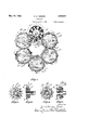
Figure 2 is a view of the same'in end elevation as seen from the right hand in Figure 1. g
Figure 3 is an extended sectional view of the transmitting gearing on a larger scale ythan that of Figures 1 and 2.
Figure 4 is a view in elevation as seen from the lane indicated by the broken line 4--4 of liigure 3.
Figure 5 is a detail view in section on the plane indicated by the broken line 5-5 of Figure 1, on a larger scale, showing the single toothed ratchet engagement between the main shaft and the eccentric which forms part of the reduction gearing.
Figure 6 is a detail View in section on the plane indicatedby the broken line 6 6 of Figure 1.A
Figure 7 is a detail view of the ldial and wheel arrangement shown diagrammatically inv Figure 2. l
Figure 8 is a view on the line 8-8 of Figure 9, looking in the direction of the arrows.
Figure 9 is a detail view showing the gears on the shaft carrying the dial h?.
Figure 10 is a detail view on the line 10-1() of Figure 11, looking in the direction of the arrows.v
Figure 11 is a detail view showing the gears on the shaft carrying the dial ha In the embodiment of the invention represented in the drawings the odometer a is shown as threaded into the inner hub b of the vehicle wheel. The non-rotating axle c is shown as carrying an arm c1 arranged for coaction in the usual manner with the arm al of the odometer mechanism to hold the arm d from rotation, so that the odometer mechanism shall be. actuated through the rotation of the casing a, the inner hub and the wheel of the vehicle. The hub d1 of the arm d is supported in a ball bearing d2 which is carried by a relatively stationary internal gear eheldin place against the plate e8 of a supporting frame e1 of the odometer mechanism b a ring e2 threaded into the casing a. This 1nternal gear e, it will be observed, rotates with the wheel and is engaged by one of a pair of compound eccentric gears f, f1 through which motion is imparted to an internal gear g. The latter, through an Oldham coupling g1, imparts motion tothe main shaft h, which may be journaled in a hub e2 on plate e". The shaft 7i, through a gear i, drives the first of the odometer dials indicated at h2, ha, etc. Motion is transmitted from one dial to the next in order through transmitting gearing of usual character, indicated at 2, is, etc., in Figure 3. These dials, as shown in Figure 2, are arranged about the axis of the odometer, the figures on the dials being read through sight openings k1 in a dial plate 7c which is held in position by a spring ring k2. The compound eccentric lgears f, f1 are carried by an eccentric Z which is loose on the hub d1. A shaft d3 is formed with a disk upon which a gear g is journaled, shaft d3 and hub Z1 being separate elements to enable the shaft and disk to be inserted through the eccentric l. In' this manner, the shaft da serves as a centering stud. A spring-pressed pawl or dog Z1, having a single ratchet tooth d, is carried by the eccentric for engagement with the hub d1 upon forward motion of the wheel. When the eccentric is thus held against rotation, the compound gears f and f1, which are driven by gear c rotating with the wheel, are caused to move about the eccentric, to impart reduced motion to gear g, and thence to shaft h. It will be seen that when the pawl rides idly over the single toothed ratchet d* when the vehicle is driven backward. the gear g will not be caused to rotate and the odometer mechanism will register only when the vehicle is driven forward.
It will be understood that while the odometer mechanism is in fact actuated by the rotation of the odometer as a whole with respect to the hub d1 and the shaft c, the eil'ect is the-same as if the odometer were held stationary and the shaft c and its appurtenances were rotated.
It will be observed that the dials h2, Ls etc., and the transmitting gearing i2, z" etc., are supported on spindles e12 which are secured at one end in the plate es of the supporting frame e1, es, and at the other end in the dial plate k, through the sight openings k1 in which the dials may be read. The dials are th`us supported in a compact circular group about the axis of the odometer.
On movement of the vehicle wheel, shaft h through gear z' drives gear il continuously (see especially Figures 7 to 11). On the shaft which carries gear i1 there is mounted a single toothed gear i which drives a ten toothed gear i on the next shaft, thus effecting a ten to 1 reduction in motion between adjacent shafts. The shaft which carries the gear i is provided with a single toothed gear 'in' for driving ten toothed gear i on the next shaft. Locking wheels i, i, i, etc. are mounted on the respective shafts to prevent overrunning and backlash. Gears i, i, i and i" a're each driven from the respective preceding shafts by mechanism exactly like that just described except for the relative positions of the gears on the shafts as shown in Figure 3. In as much as ten to one reduction gearing between shafts is well known, the present construction will not be further described.
It will be understood that various details in construction and arrangement may be made to suit different conditions of use, and except as pointed out in the accompanying claim the invention is not restricted to the particular construction shown and described herein.
I claim as my invention:
In an odometer having a casing and series of dials and transmitting gears supported by a frame and spaced circumferen-
Priority Applications (1)
| Application Number | Priority Date | Filing Date | Title |
|---|---|---|---|
| US267167A US1908801A (en) | 1928-04-04 | 1928-04-04 | Odometer |
Applications Claiming Priority (1)
| Application Number | Priority Date | Filing Date | Title |
|---|---|---|---|
| US267167A US1908801A (en) | 1928-04-04 | 1928-04-04 | Odometer |
Publications (1)
| Publication Number | Publication Date |
|---|---|
| US1908801A true US1908801A (en) | 1933-05-16 |
Family
ID=23017602
Family Applications (1)
| Application Number | Title | Priority Date | Filing Date |
|---|---|---|---|
| US267167A Expired - Lifetime US1908801A (en) | 1928-04-04 | 1928-04-04 | Odometer |
Country Status (1)
| Country | Link |
|---|---|
| US (1) | US1908801A (en) |
Cited By (2)
| Publication number | Priority date | Publication date | Assignee | Title |
|---|---|---|---|---|
| US2674423A (en) * | 1943-12-31 | 1954-04-06 | Bendix Aviat Corp | Automatic pilot |
| US3233828A (en) * | 1964-11-10 | 1966-02-08 | Goodyear Tire & Rubber | Wheel life indicator |
-
1928
- 1928-04-04 US US267167A patent/US1908801A/en not_active Expired - Lifetime
Cited By (2)
| Publication number | Priority date | Publication date | Assignee | Title |
|---|---|---|---|---|
| US2674423A (en) * | 1943-12-31 | 1954-04-06 | Bendix Aviat Corp | Automatic pilot |
| US3233828A (en) * | 1964-11-10 | 1966-02-08 | Goodyear Tire & Rubber | Wheel life indicator |
Similar Documents
| Publication | Publication Date | Title |
|---|---|---|
| US1671553A (en) | Counter | |
| US1908801A (en) | Odometer | |
| US1461956A (en) | Odometer-train-resetting device | |
| US2713971A (en) | Counting devices | |
| US2642716A (en) | Timepiece movement comprising a differential gear | |
| US1471306A (en) | Resetting counter | |
| US1418507A (en) | Counter train | |
| US718104A (en) | Registering mechanism. | |
| US1394455A (en) | Register | |
| US1400197A (en) | Revolution-counter resetting | |
| US1054363A (en) | Resetting counter. | |
| US3333768A (en) | Odometer | |
| US1654441A (en) | gebmany | |
| US950546A (en) | Counter. | |
| US2556762A (en) | Lydfors | |
| US1378428A (en) | Speedometer | |
| US1196495A (en) | Register. | |
| US1100278A (en) | Mechanism for totaling the number of revolutions of a rotary body. | |
| US1604604A (en) | Mechanical movement | |
| US1280466A (en) | Comptometer. | |
| US1502719A (en) | Odometer | |
| US1408718A (en) | Drive for weight-moved clocks | |
| US1095832A (en) | Counting mechanism. | |
| US764778A (en) | Counter. | |
| US1044710A (en) | Counter. |