US1908752A - Coin controlled device - Google Patents
Coin controlled device Download PDFInfo
- Publication number
- US1908752A US1908752A US545639A US54563931A US1908752A US 1908752 A US1908752 A US 1908752A US 545639 A US545639 A US 545639A US 54563931 A US54563931 A US 54563931A US 1908752 A US1908752 A US 1908752A
- Authority
- US
- United States
- Prior art keywords
- coin
- slide
- aperture
- guide
- stroke
- Prior art date
- Legal status (The legal status is an assumption and is not a legal conclusion. Google has not performed a legal analysis and makes no representation as to the accuracy of the status listed.)
- Expired - Lifetime
Links
- 230000033001 locomotion Effects 0.000 description 37
- 230000000994 depressogenic effect Effects 0.000 description 28
- 230000007246 mechanism Effects 0.000 description 22
- 230000009977 dual effect Effects 0.000 description 4
- ZQWBGSZBBGYKNV-UHFFFAOYSA-N 2-(4-ethoxyphenyl)-1,3-bis(4-methoxyphenyl)guanidine;hydrochloride Chemical compound Cl.C1=CC(OCC)=CC=C1N=C(NC=1C=CC(OC)=CC=1)NC1=CC=C(OC)C=C1 ZQWBGSZBBGYKNV-UHFFFAOYSA-N 0.000 description 1
- 241000721047 Danaus plexippus Species 0.000 description 1
- 241000237858 Gastropoda Species 0.000 description 1
- 230000015572 biosynthetic process Effects 0.000 description 1
- 230000000295 complement effect Effects 0.000 description 1
- 238000010276 construction Methods 0.000 description 1
- 230000000694 effects Effects 0.000 description 1
- 230000037431 insertion Effects 0.000 description 1
- 238000003780 insertion Methods 0.000 description 1
- 238000004519 manufacturing process Methods 0.000 description 1
- 239000007779 soft material Substances 0.000 description 1
Images
Classifications
-
- G—PHYSICS
- G07—CHECKING-DEVICES
- G07D—HANDLING OF COINS OR VALUABLE PAPERS, e.g. TESTING, SORTING BY DENOMINATIONS, COUNTING, DISPENSING, CHANGING OR DEPOSITING
- G07D5/00—Testing specially adapted to determine the identity or genuineness of coins, e.g. for segregating coins which are unacceptable or alien to a currency
Definitions
- This invention relates to a manually operated, coin-controlled mechanism adapted for use with various mechanical devices which release one or more objects to the op- 5 erator upon deposit of a coin and operation of the device of this invention.
- An object of the invention is to provide a device of the class described which may be operated only by a coin of fixed denomination.
- Another object is to provide such a device which is non-operable with any other coin or imitation thereof except the coin for which the device is adapted for use.
- Another object is to provide a device of the class described in which an operator who deliberately or accidently makes use of a coin of wrong denomination, must withdraw the coin from the device rather than lose the coin 9 upon insertion thereof as in similar mecha-.
- Another object is to provide a mechanism of this kind which is simple and eflicient in construction and operation.
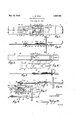
- Fig. 1 is a top plan view of the device of this invention in its normal position and in 0 readiness to receive and be operated by a coin.
- Fig. 2 is a cross-sectional view taken on the line 22 of Fig. 1.
- Fig. 3 is a top plan view of the device after complete operation thereof and with certain of the parts removed.
- Fig.- 4 is a top plan view of the guide plate of this invention with parts broken away.
- Fig. 5 is a longitudinal cross-sectional view of the mechanism after complete operation thereof.
- Fig. 6 is a longitudinal cross-sectional view after partial operation thereof, showing the resultant relative positions of the parts after operation of the device without the use of a com. 7
- Fig. 7 is a bottom plan view of 'a modified form of the invention in the normal inoperative position.
- F i 8 is a view taken on the line 88 of Fig.
- the device of this invention is designed to preclude improper opera'tion of the device and at the same time is designed to return to the operator any other coin but the one which is adapted to successfully operate the mechanism.
- the device is to be operated by use of a five cent piece and the use of a coin of smaller size, whether it be a one cent or a ten cent piece will require that the operator retract the operating lever and remove the coin therefrom.
- coin-controlled mechanisms of this character when the attempt was made to operate them by'other than thepre-determined coin, resulted in the operators losing the coin without actuating the mechanism with which the device was associated.
- the device comprises a guide plate 12 having the bottom 13 and the lateral flanges 14 and 15 overhanging the upper face of the bottom 13 in spaced relationship therewith.
- the bottom 13 is provided with a circular aperture 16 adjacent the outer end of the guide plate, a central substantially rectangular aperture 17, and a coin-release aperture 18. Adjacent the inner side of aperture 18 the bottom 13 of the plate is pressed outwardlyto provide the depressed ledge 19.
- the bottom of the plate is provided with a longitudinal channel 20, extending from the outer edge of the guide plate to a short distance beyond the coin-release aperture.
- the guide plate 12 passes through a. vertical support plate 24: which is provided adjacent the edges of the guide plate with suitable supporting lugs 25.
- the main movable member of the mechanism consists of a strip-like member 26 which is receivable within the guideway formed by the flanges 14 and 15 of the bottom plate 13. 90
- Member 26 has a circular coin-receiving aperture 27 adapted in the inoperative position of the device to register with the aperture 16 of the bottom plate, as shown in Fig. 2, but of greater dimensions so that a coin inserted within the aperture 27 is supported with an upwardly turned handle portion 31 which is receivable between the inner edges of the flanges 14 and 15.
- the border portions of aperture 27 are pressed downwardly to provide the centrally disposed lugs 46 and 47 which during operation of the device are adapted to move through the channel 20 of the guide plate.
- an angled slide portion 48 may be provided in the top face of the member 26 and above the lug 47.
- top plate 32 is attached upon the flanges 14 and 15 and is formed with an integral flange 33 which seats within a countersunk portion in the vertical plate 24 (Fig. 2)
- Top plate 32 is formed with a central depressed portion or channel 34 which flares outwardly at the inner end of the plate, as indicated at 35. Within the flared portion 35 the plate is pressed upwardly as at 36 to the same level as the side portions of the plate. Centrally thereof, the plate 32 is formed with upwardl projecting transverse journal members 3 and 38.
- the central depressed portion 34 of the plate 32 is provided with a longitudinally extending perforation 39.
- a finger or trigger 40 having integral arms or trunnions 41 is journalled by means of said trun-nions within the journal members 37 and 38 and is adapted for pivotal movement through the aperture 39.
- the trigger 40 at its free end is formed with an integral stud 42 (Figs. 2 and 7).
- Said trigger is normally urged to pivotal movement through aperture 39 by means of a spring 43 attached as at 44 upon the upper face of the portion 36 of the plate 32. and having its free end 45 overhanging and in contact against the trigger 40.
- the present invention provides av means for precluding operation of the device when a magnetic coin'or slug is attempted to be used.
- These means comprise an abutment member 49 positioned upon the guide plate rearwardly of the coin-release aperture 18.
- Member 49 is provided with an arm 50 projecting forwardly above the depressed portion 19 and the coin-release aperture 18 of the guideplate.
- Member 49 is rendered immovable in position by use of a pair of proections' 51 to seat in complementary depressions 63 in the guide plate.
- a screw bolt 52 passes loosely through'the abutment member 50 and likewise serves to clamp down upon said on its bottom face and adapted abutment member a magnet 53 which extends forwardly beyond the end of the arm 50.
- a suitable washer 54 and nut 55 may be used in properly securing the respective parts together.
- a non-magi etic coin of the predetermined size is deposited upon the guide plate within the aperture 27 of the slidable member .26 and said slide member is then moved inwardly by means of the handle portion 31.
- the stud 42 of the trigger 40 is projected into the space between the innermost edge of such coin and the border of the aperture 27 whereby further movement of the slide member is precluded. It will be ob-- which pas'sed inwardly of the device and wasthis time the stud 42 of the trigger 20 reproprojected therefrom by the trigger without accomplishing effective operation of the associated mechanism.
- the trigger When no coin at all is inserted in, the slide member, and the lever is idly pushed inwardly, the trigger is projected through the coinreceiving aperture27, as shown in Fig. 6, and projects downwardly through the rectangular aperture 17 of the guide plate into abutment with the innermost border of said aperture whereby the slide member is effectively locked against further inward movement.
- the innermost edge of the aperture 27 In retracting the Slide member to its normal position, the innermost edge of the aperture 27 carries the trigger upwardly to its. normally contacting position against the upper face of the slide member.
- FIGs. 7 and 8 A slightly modified form of the invention is illustrated in Figs. 7 and 8.
- the guide plate is susbtantially identical with the one heretofore described except that a restricted aperture 56 is provided between the coin-.
- the slide. member 59 is substantially shorter than the form heretofore described the aperture 63 extending longitudinally of the slide member from the end thereof up to and communicating with the coin-receiving aperture 64 of the slide member.
- the slide member 59 has atttached to its inner end 65 a downwardly projecting arm 60 which is adapted to move through the apertures 56, 57, and 58 and at the termination of the inward movement of the slide member is received in the'restricted end aperture 61 at which point the arm 60 is adapted to effect operation of the associated mechanism to which it is attached.
- the device of this invention islikewise adapted to circumvent the use of non-metallic slugs or coins of materail such as cardboard.
- the acutely angled forward edge of trigger stud 42 is driven into the soft material of such a coin by the action of the tensioned spring 43 thereon whereby further inward movement of the slide member is precluded.
- a coin-control device adapted to actuate enclosed mechanism associated therewith, said device comprising a support plate secured upright in the wall of the mechanismenclosing means, an elongated guide plate provided with lateral overhanging flanges, said plate being secured in and extending on both sides of the support plate and having an enlarged central aperture and a central longitudinally-extending channel, a depressed portion in the guide plate adjacent the inner end thereof and having a coin-release aperture therein, a strip-like member slidable upon the guide between the flanges thereof, said slidable memberbeing provided with an extended aperture and with a circular aperture adapted to embrace snugly a coin of pre-determined diameter deposited therein upon the guide plate, a lug projecting downwardly of the front edge of the coin-receiving aperture and adapted for movement through said guide plate channel, an apertured top plate secured upon the flanges of the guide plate above the central aperture thereof, a downwardly-urged trigger mounted on the top plate and having a stud on its free end normally
- the slidable member when provided with a non-magnetic coin of the predetermined size being inwardly movable the full length of said extended aperture and being adapted upon such movement to actuate the associated 2.
- a coin-controlled device adapted to actuate .other mechanism associated therewith, said device comprising a support member, a horizontally-disposed guide plate se- 5 cured upon the support member and having foration, said thereby, said device comprising a the slide member, an apertured top plate mounted upon the guide plate above the slide member, a downwardly-urged trigger mounted on the top plate and normally held in con tact upon the slide member, said trigger being adapted when the slide member is actuated inwardly without a coin, to be projected through the coin-receiving aperture of the slide member and the apertured intermediate section of the guide plate into abutment with said plate for precluding complete inward movement of the slide member, outward,
- a magnet positioned upon said abutment mem-. her and extending forwardly beyond the end of said projecting arm, a non-magnetic coin of the pre-determined size being adapted to be moved by the slide member along the guide plate into said depressed portion and release aperture whereby abutment of the coin against said arm is avoided, and complete inward movement of the slide member may be effected and a magnetic coin of the predetermined diameter being held upwardly by the magnet whereby abutment thereof with said arm results, said trigger,-when a 4 coin of less than the pre-determined diameter is utilized, being adapted to enter the space between such coin and the border of the coinreceiving aperture for precluding further inward movement of the slide member.
- a coin-control device adapted to extend through the housing of mechanism controlled stationary elongated guide plate having an intermediate apertured section and an apertured depressed portion and an abutment at its inner end, a member slidable upon the guide plate and adapted upon complete inward movement to actuate the associated mech anism, said slidable member havin an apertured inner portion adapted. to embrace said abutment and an apertured outer portion for snugly embracing a coin of pre-determined aperture, .a downwar ed interiorly of said enclosure and in contact a ried thereby,
- a downwardly-urged trigger adapted to bear against the slidable member and permitting passage therebeneath of a coin of the pre-determined diameter, said trigger being adapted upon use of a coin of less than the predetermined diameter, to be projected into the path of such coin, and to be projected through the coin-receiving aperture and the intermediate aperture of the guide plate into abutment with said plate upon actuation of the slidable member without a coin, and a magnet positioned upon and extending forwardly of said abutment and above said apertured depressed portion of the guide plate, a magnetic coin being upheld by said magnet and moved into contact against said abutment upon inward movement of the slidable member whereby full operation of said member is precluded, a non-magnetic coin being carried by the slidable member into said depressed portion and beneath the abutment whereby full operation of said member ispermitted, said coin being ejected through the aperture of said depressed portion.
- a coin-control device for actuating en- ..closed mechanism associated therewith, said device comprising an elongated guide plate adapted to extend interiorly and exteriorly of the mechanism enclosure and provided with an intermediate aperture andwith a. coin release aperture adjacent its inner end,
- abutment positioned upon said inner end and having an arm extending forwardly above said depressed portion, a coin-moving member slidable on the guide plate and adapted upon complete inward movement thereof to actuate the associated mechanism, said member being provided with an extended apertured portion embracing said abutment and an aperture at its outer end' for'snugly embracing a coin of pro-determined diameter deposited upon the y urged trigger mountagainst the slidable member and permitting movement therebeneath of said member and of a coin of the predetermined diameter carthe trigger being projected into the path of the slidable member or coin respcctively when no coin or a coin of less than t e pre-determined diameter is utilized, and a magnet positioned above and projecting forwardly of said extending arm andadapted to uphold a magnetic coin for effecting abutment thereof against the end of saidarm to preclude-full inward movement of the slidable member, a non-magnetic coin being carried by the slidable
- a coin control device adapted to actuate enclosed mechanism associated therewith
- said device comprising a channeled stationary guide plate extending interiorly and exteriorly of the mechanism-enclosing means, a depressed portion adjacent the inner end of said plate and having a coin-release aperture therein, an abutment -member extending above said depressed portion, a slide member embracing said abutment and having limited movement-on the guide plate inwardly and outwardly of the enclosing means, said slide member being adapted upon full inward movement to actuate the associated mechanism, an apertured portion adjacent the outer end of the slide member for snugly receiving a coin of pre-determined diameter deposited flat upon the guide plate, said apertured portion being adapted to carry a nonmagnetic coin of such diameter into said depressed portion upon inward movement of the slide member, a stud projecting downwardly of the slide member in front of said coin-receiving aperture, and extending into the channel of the guide plate, said stud be-:
- a non-magnetic coin to said coin release aperture after movement of the coin into said depressed portion
- a coin-control device for actuating enclosed mechanism associated therewith, said device comprising an elongated guide plate adapted to extend inwardly and outwardlv of the mechanism-enclosing means, a depressed portion adjacent the inner end of said plate and having a coin-release aperture therein, a member slidable longitudinally upon said plate, means on the'slidable member for efiecting movement into said de-.
- the slidable member after release of such coin being adapted for final inward movement whereby to actuate the associated mechanism, means precluding such movement of the slidable member when provided with a coin of less than the pre-determined diameter, a magnet positioned above said depressed portion and preventing movement thereinto of a magnetic coin of the pre-determined diameter, and an abutment member adjacent the magnet for abutting a magnetic coin to reclude final inwardvmovement of the slida le'member.
- a coin-controlled device comprising a guide plate having a depressed portion with a coin release aperture therein, a member slidable on the plate and provided with a coin receiving aperture whereby a coin of specific diameter may-be moved along the plate to the depressed portion and with a stud whereby such coin may be moved through the depressed portion to the coin release aperture, the slidable member after release of a coin from said release aperture being adapted to operate associated mecha-v nism, means precluding full inward move- -ment of the slidable member upon use of a. coin not of the specific diameter, and means slide; a pocket formed in said guide to receive the coin from said slide before the slide reaches the limit of its full stroke; and means on said slide to move the coin in said pocket in accordance with the direction of travel of said slide.
- a slide provided with an aperture to receive a coin; a guide for said slide and means on said guide to permit a full stroke of predetermined length when said slide contains a coin, and to prohibit the predetermined stroke when no coin is in said slide; a pocket formed in said guide to receive the coin from said slide before the slide reaches the limit of its full stroke; and dual means on said slide to move the coin insaid pocket in accordance with the direction of travel of said slide.
- a slide provided with an aperture to receive a coin; a guide for said slide and means on said guide to permit a full stroke of predetermined length when said slide contains a coin, and to prohibit the predetermined stroke when no coin is in said slide; a pocket formed in said guide to receive the coin from said slide before the slide reaches the limit of its full stroke; and opposed means on said slide to move the coin slide contains a coin, and to prohibit the predetermined stroke when no coin is in said slide; a pocket formed in said guide to receive the coin from said slide before the slide reaches the limit of its full stroke, said pocket substantially closed at one end and terminating at the opposite end in a coin release opening; means on said slide tomove the coin out of said pocket to the coin release opening upon the full operative stroke of said slide; and additional means on said slide to cause the pocketed coin to be trapped between the closed end of said pocket and said means upon the return stroke of said slide after an incomplete o erative stroke.
- a slide provided with an aperture to receive a coin; a guide for said slide and means on'said guide to permit a full stroke of predetermined length when said slide contains a coin, and to prohibit the predetermined stroke when no coin is in said slide; a pocket formed in said guide to receive the coin from said slide before the slide reaches the limit of its full stroke; and dual means disposed on opposite sides of the coin aperture in said slide to move the coin in said pocket in accordance with the direction of travel of said slide.
- a slide provided with an aperture to receive a coin; a guide for said slide and means on said guideto permit a full stroke of .predetermined length when said slide contains a coin, and to prohibit the predetermined stroke' when no coin is in said slide; a pocket formed in said guide to receive the coin from said slide before the --sliele reaches the limit of its full stroke; and
- a coin slide provided with I a slot; a guide for said slide; a magnet disposed' above said slide over said slot; and a member extending into said slot and cooperating with said magnet to limit the full travel of said slide when a magnetic element is carried bysaid slide in place of the intended coin.
- a slide provided with an aperture to receive a coin; a slot in said slide; a guide for said slide; a magnet disposed above said slide and over said slot; means extending into said slot .to permit the full operative travel of said slide when carrying a coin, said means cooperating with said magnet to prohibit said full operative travel when the slide carries a magnetic substitute for the coin; and means on said guide to prevent a full strokeof said slide when containing no coin.
- av slide provided with an aperture to receive a coin
- a guide for said slide and means on said guide to permit a full stroke of predetermined length when said slide contains a coin, and to prohibit the predetermined stroke when no coin is in said slide
- a pocket formed in said guide to receive the coin from said slide before the slide reaches the limit of its full stroke
- means on said slide to move the coin out of said pocket upon the full operative stroke of said slide
- additional means on said slide to jam a coin against a side of said pocket upon the return stroke of said slide after an incomplete operative stroke.
- a slide provided with an determined stroke when no coin is in said 4 slide; a pocket formed in said slide to receive the coin from said slide before the slide reaches the limit of its full stroke and .dual means ori said slide to move thecoin in said pocket in accordance with the direction of travel of said slide, said means comprising projections from said slide which together with said pocket permits release of the pock- .eted coin upon the full operative stroke of said slide, and to jam said coin upon the return stroke of said slide after an incomplete operative stroke.
- a slide provided with an aperture to receive a coin; a guide for said slide and means on said guide to permit a full stroke of predetermined length when said slide contains a coin, and to prohibit the predetermined stroke when no coin is in said slide; a horizontally disposed pocket formed in said guide to receive the coin from said slide before the slide reaches the limit of its full stroke; means on said slide to move the coin out of said pocket upon the full operative stroke 'of said slide; and additional means on said slide to jam acoin against a side of said pocket upon the return stroke of said slide after an incomplete voperative stroke.
- a slide provided with an aperture to receive a coin; a guide for said slide and means on said guide to permit a full stroke of predetermined length when said slide contains a coin, and to prohibit the predetermined stroke when no coin is in said slide; a pocket formed in said guide to receive the coin from said slide before the slide reaches the limit of its full stroke; and duel means displaced from the plane of said slide to move the coin in said pocket in accordance with the direction of travel of said slide.
- a slide provided with an aperture-to receive a coin
- a guide for said slide and means on said guide to permit a full stroke of predetermined length when said slide contains a coin, and to prohibit the predetermined stroke when no coin is in said slide
- a pocket formed in said guide to receive the coin from said slide before the slide reaches the limit of its full stroke
- duel means comprising projections expressed from the plane of said slide to move the coin in said pocket in accordance with the direction of travel of said slide.
- a slide provided with a coin receiving aperture; a slot in said slide; a guide for said slide; a magnet carried by said guide and disposed above said slide and over said slot; and means carried by said guide and extending into said slot to permit the full operative travelof said slide when carrying a coin,said means cooperating with said magnet to prohibit said full operative travel when the slide carries a magnetic substitute for the coin.
- a slide provided with an aperture to receive a coin; a slot in said slide; a guide for said slide; a magnet disposed above said slide and over said slot; means extending into said slot to permit the full operative travel of said. slide when carrying a coin, said means having an extension cooperating with said magnet to prohibit said full operative travel when the slide carries a magnetic substitute for the coin; and means on said guide to prevent a full stroke of said slide when containing no coin.
Landscapes
- Physics & Mathematics (AREA)
- General Physics & Mathematics (AREA)
- Control Of Vending Devices And Auxiliary Devices For Vending Devices (AREA)
Description
May 16, 1933.
L. HALL COIN CONTROLLED DEVICE Filed June 20, 1931 L ou is M. Hall I I 52 5 J3 7Z9 O/W Patented May 16, 1933 UNITED STATES IATENT OFFICE LOUIS M. HALL, 013 FORT THOMAS, KENTUCKY, ASSIGNOR, BY DmECT AND MESNE ASSIGNMENTS, OF ONE-HALF TO THE MONARCH TOOL & MANUFACTURING COMPANY, OF CINCINNATI, OHIO, A CORPORATION 01 OHIO, AND ONE-HALF TO WALTER A. TRATSCH, OF CHICAGO, ILLINOIS com CONTROLLED nnvrcn Application filed June 20,
This invention relates to a manually operated, coin-controlled mechanism adapted for use with various mechanical devices which release one or more objects to the op- 5 erator upon deposit of a coin and operation of the device of this invention.
An object of the invention is to provide a device of the class described which may be operated only by a coin of fixed denomination.
Another object is to provide such a device which is non-operable with any other coin or imitation thereof except the coin for which the device is adapted for use.
Another object is to provide a device of the class described in which an operator who deliberately or accidently makes use of a coin of wrong denomination, must withdraw the coin from the device rather than lose the coin 9 upon insertion thereof as in similar mecha-.
nisms heretofore constructed.
Another object is to provide a mechanism of this kind which is simple and eflicient in construction and operation. I
These and other objects are attained by the means described herein and illustrated in the accompanying drawing, in which:
Fig. 1 is a top plan view of the device of this invention in its normal position and in 0 readiness to receive and be operated by a coin. Fig. 2 is a cross-sectional view taken on the line 22 of Fig. 1.
Fig. 3 is a top plan view of the device after complete operation thereof and with certain of the parts removed.
Fig.- 4 is a top plan view of the guide plate of this invention with parts broken away.
Fig. 5 is a longitudinal cross-sectional view of the mechanism after complete operation thereof.
Fig. 6 is a longitudinal cross-sectional view after partial operation thereof, showing the resultant relative positions of the parts after operation of the device without the use of a com. 7
1931. Serial No. 545,639.
Fig. 7 is a bottom plan view of 'a modified form of the invention in the normal inoperative position. I
F i 8 is a view taken on the line 88 of Fig.
The device of this invention is designed to preclude improper opera'tion of the device and at the same time is designed to return to the operator any other coin but the one which is adapted to successfully operate the mechanism. As contemplated herein, the device is to be operated by use of a five cent piece and the use of a coin of smaller size, whether it be a one cent or a ten cent piece will require that the operator retract the operating lever and remove the coin therefrom. Heretofore coin-controlled mechanisms of this character, when the attempt was made to operate them by'other than thepre-determined coin, resulted in the operators losing the coin without actuating the mechanism with which the device was associated.
With reference to the drawing: The device comprises a guide plate 12 having the bottom 13 and the lateral flanges 14 and 15 overhanging the upper face of the bottom 13 in spaced relationship therewith. The bottom 13 is provided with a circular aperture 16 adjacent the outer end of the guide plate, a central substantially rectangular aperture 17, and a coin-release aperture 18. Adjacent the inner side of aperture 18 the bottom 13 of the plate is pressed outwardlyto provide the depressed ledge 19. The bottom of the plate is provided with a longitudinal channel 20, extending from the outer edge of the guide plate to a short distance beyond the coin-release aperture. The guide plate 12 passes through a. vertical support plate 24: which is provided adjacent the edges of the guide plate with suitable supporting lugs 25.
The main movable member of the mechanism consists of a strip-like member 26 which is receivable within the guideway formed by the flanges 14 and 15 of the bottom plate 13. 90
A top plate 32 is attached upon the flanges 14 and 15 and is formed with an integral flange 33 which seats within a countersunk portion in the vertical plate 24 (Fig. 2) Top plate 32 is formed with a central depressed portion or channel 34 which flares outwardly at the inner end of the plate, as indicated at 35. Within the flared portion 35 the plate is pressed upwardly as at 36 to the same level as the side portions of the plate. Centrally thereof, the plate 32 is formed with upwardl projecting transverse journal members 3 and 38. The central depressed portion 34 of the plate 32 is provided with a longitudinally extending perforation 39. A finger or trigger 40 having integral arms or trunnions 41 is journalled by means of said trun-nions within the journal members 37 and 38 and is adapted for pivotal movement through the aperture 39. The trigger 40 at its free end is formed with an integral stud 42 (Figs. 2 and 7). Said trigger is normally urged to pivotal movement through aperture 39 by means of a spring 43 attached as at 44 upon the upper face of the portion 36 of the plate 32. and having its free end 45 overhanging and in contact against the trigger 40.
The present invention provides av means for precluding operation of the device when a magnetic coin'or slug is attempted to be used. These means comprise an abutment member 49 positioned upon the guide plate rearwardly of the coin-release aperture 18. Member 49 is provided with an arm 50 projecting forwardly above the depressed portion 19 and the coin-release aperture 18 of the guideplate. Member 49 is rendered immovable in position by use of a pair of proections' 51 to seat in complementary depressions 63 in the guide plate. A screw bolt 52 passes loosely through'the abutment member 50 and likewise serves to clamp down upon said on its bottom face and adapted abutment member a magnet 53 which extends forwardly beyond the end of the arm 50. A suitable washer 54 and nut 55 may be used in properly securing the respective parts together.
. The operation of the device is as follows: A non-magi etic coin of the predetermined size is deposited upon the guide plate within the aperture 27 of the slidable member .26 and said slide member is then moved inwardly by means of the handle portion 31. At
mains in contact against the unapertured portions of the slide member and continues in similar contact against the upper face of the coin, there being substantially no space intervening between the edge of the coin and the border portions of the aperture 27. When the stud reaches the outermost edge of the coin it is projected downwardly to a slight extent into the angled slide portion 48 whereupon said stud immediately rises to the normal level of the slide member and so continues until complete inward movement of said member. When the coin has been carried to the depressed portion 19 it moves down wardly into said depressed portion and is carried through said depressed portion to the coin-release aperture 18, by means of the downwardly projecting stud 47. It will be observed that the coin as ositioned in said depressed portion comes eneath the jecting arm 50 whereby interference of the coin with said arm is precluded. Complete inward operation of the slide member may thus be effected, the arm 50, in'the final movement of said slide member, being adapted to be received freely in the restricted aperture 30 and the aperture 27. It will be understood that the slide member, in its movement after the release of the non-magnetic coin, is adapted to actuate the mechanism with which the coin-control device'is associated. In other words, it is the final stage of'move ment of the slide member which is effective in operating the associated mechanism.
Should the attempt be made to operate the device with a coin of less than the predetermined diameter, the stud 42 of the trigger 40 is projected into the space between the innermost edge of such coin and the border of the aperture 27 whereby further movement of the slide member is precluded. It will be ob-- which pas'sed inwardly of the device and wasthis time the stud 42 of the trigger 20 reproprojected therefrom by the trigger without accomplishing effective operation of the associated mechanism.
. If a magnetic coin of the predetermined size is attempted to be used, ,said coin passes through the device in the regular manner as above described as far as the magnet 53 at which time it is drawn against the under face of said magnet and is precluded from moving downwardlyinto the depressed portion 19. Further inward movement oftheslide member 26 results in abutment of the innermost edge of the magnetic coin against the end of the arm 50 so that effective inward operation of the slide member is prevented and the operator is required to retract the slide member and remove the magnetic coin therefrom.
When no coin at all is inserted in, the slide member, and the lever is idly pushed inwardly, the trigger is projected through the coinreceiving aperture27, as shown in Fig. 6, and projects downwardly through the rectangular aperture 17 of the guide plate into abutment with the innermost border of said aperture whereby the slide member is effectively locked against further inward movement. In retracting the Slide member to its normal position, the innermost edge of the aperture 27 carries the trigger upwardly to its. normally contacting position against the upper face of the slide member.
A slightly modified form of the invention is illustrated in Figs. 7 and 8. Herein the guide plate is susbtantially identical with the one heretofore described except that a restricted aperture 56 is provided between the coin-.
release aperture 57 and the rectangular aperture 58. The slide. member 59 is substantially shorter than the form heretofore described the aperture 63 extending longitudinally of the slide member from the end thereof up to and communicating with the coin-receiving aperture 64 of the slide member. Upon full inward movement of the slide member the end 65 thereof contacts the abutment member 49 for limiting movement of the slide member. The slide member 59 has atttached to its inner end 65 a downwardly projecting arm 60 which is adapted to move through the apertures 56, 57, and 58 and at the termination of the inward movement of the slide member is received in the'restricted end aperture 61 at which point the arm 60 is adapted to effect operation of the associated mechanism to which it is attached. It will be seen that the depressed coin-receiving ledge 62 is rendered smaller due to the formation of the restricted aperture 56, but its size is amply sufficient to properly support the non-magnetic coin deposited thereon. The operation of this form of the invention is substantially identical with the foregoing description.
It should be noted that the device of this invention islikewise adapted to circumvent the use of non-metallic slugs or coins of materail such as cardboard. The acutely angled forward edge of trigger stud 42 is driven into the soft material of such a coin by the action of the tensioned spring 43 thereon whereby further inward movement of the slide member is precluded.
lVhat is claimed is:
1. A coin-control device adapted to actuate enclosed mechanism associated therewith, said device comprising a support plate secured upright in the wall of the mechanismenclosing means, an elongated guide plate provided with lateral overhanging flanges, said plate being secured in and extending on both sides of the support plate and having an enlarged central aperture and a central longitudinally-extending channel, a depressed portion in the guide plate adjacent the inner end thereof and having a coin-release aperture therein, a strip-like member slidable upon the guide between the flanges thereof, said slidable memberbeing provided with an extended aperture and with a circular aperture adapted to embrace snugly a coin of pre-determined diameter deposited therein upon the guide plate, a lug projecting downwardly of the front edge of the coin-receiving aperture and adapted for movement through said guide plate channel, an apertured top plate secured upon the flanges of the guide plate above the central aperture thereof, a downwardly-urged trigger mounted on the top plate and having a stud on its free end normally in contact against the slidable member, said trigger being adapted to be projected through the empty coin-receiving aperture and the central aperture of the guide plate upon inward movement of the slidable member and to abut the edge of said central aperture for precluding further inward movement of the slidable member, an
abutment on theinner end of the guide plate and adapted to project into the extended aperture of the slidable member, a magnet positioned upon and extending forwardly of the abutment above the coin-release aperture, the slidable member when provided with a non-magnetic coin of the predetermined size being inwardly movable the full length of said extended aperture and being adapted upon such movement to actuate the associated 2. A coin-controlled device adapted to actuate .other mechanism associated therewith, said device comprising a support member, a horizontally-disposed guide plate se- 5 cured upon the support member and having foration, said thereby, said device comprising a the slide member, an apertured top plate mounted upon the guide plate above the slide member, a downwardly-urged trigger mounted on the top plate and normally held in con tact upon the slide member, said trigger being adapted when the slide member is actuated inwardly without a coin, to be projected through the coin-receiving aperture of the slide member and the apertured intermediate section of the guide plate into abutment with said plate for precluding complete inward movement of the slide member, outward,
movement of the slide member serving to return the trigger to its normal position, a magnet positioned upon said abutment mem-. her and extending forwardly beyond the end of said projecting arm, a non-magnetic coin of the pre-determined size being adapted to be moved by the slide member along the guide plate into said depressed portion and release aperture whereby abutment of the coin against said arm is avoided, and complete inward movement of the slide member may be effected and a magnetic coin of the predetermined diameter being held upwardly by the magnet whereby abutment thereof with said arm results, said trigger,-when a 4 coin of less than the pre-determined diameter is utilized, being adapted to enter the space between such coin and the border of the coinreceiving aperture for precluding further inward movement of the slide member. 3. A coin-control device adapted to extend through the housing of mechanism controlled stationary elongated guide plate having an intermediate apertured section and an apertured depressed portion and an abutment at its inner end, a member slidable upon the guide plate and adapted upon complete inward movement to actuate the associated mech anism, said slidable member havin an apertured inner portion adapted. to embrace said abutment and an apertured outer portion for snugly embracing a coin of pre-determined aperture, .a downwar ed interiorly of said enclosure and in contact a ried thereby,
diameter deposited upon the guide plate within said apertured portion, a downwardly-urged trigger adapted to bear against the slidable member and permitting passage therebeneath of a coin of the pre-determined diameter, said trigger being adapted upon use of a coin of less than the predetermined diameter, to be projected into the path of such coin, and to be projected through the coin-receiving aperture and the intermediate aperture of the guide plate into abutment with said plate upon actuation of the slidable member without a coin, and a magnet positioned upon and extending forwardly of said abutment and above said apertured depressed portion of the guide plate, a magnetic coin being upheld by said magnet and moved into contact against said abutment upon inward movement of the slidable member whereby full operation of said member is precluded, a non-magnetic coin being carried by the slidable member into said depressed portion and beneath the abutment whereby full operation of said member ispermitted, said coin being ejected through the aperture of said depressed portion.
4. A coin-control device for actuating en- ..closed mechanism associated therewith, said device comprising an elongated guide plate adapted to extend interiorly and exteriorly of the mechanism enclosure and provided with an intermediate aperture andwith a. coin release aperture adjacent its inner end,
a depressed portionin the guide plate disposed immediately forward of and contiguous with said coin release aperture, an
abutment positioned upon said inner end and having an arm extending forwardly above said depressed portion, a coin-moving member slidable on the guide plate and adapted upon complete inward movement thereof to actuate the associated mechanism, said member being provided with an extended apertured portion embracing said abutment and an aperture at its outer end' for'snugly embracing a coin of pro-determined diameter deposited upon the y urged trigger mountagainst the slidable member and permitting movement therebeneath of said member and of a coin of the predetermined diameter carthe trigger being projected into the path of the slidable member or coin respcctively when no coin or a coin of less than t e pre-determined diameter is utilized, and a magnet positioned above and projecting forwardly of said extending arm andadapted to uphold a magnetic coin for effecting abutment thereof against the end of saidarm to preclude-full inward movement of the slidable member, a non-magnetic coin being carried by the slidable member into and through said. depressed portion beneath said arm whereby full inward movement of the slid- (giuide plate within said able member and ejection of the coin may be effected.
5. A coin control device adapted to actuate enclosed mechanism associated therewith,
said device comprising a channeled stationary guide plate extending interiorly and exteriorly of the mechanism-enclosing means, a depressed portion adjacent the inner end of said plate and having a coin-release aperture therein, an abutment -member extending above said depressed portion, a slide member embracing said abutment and having limited movement-on the guide plate inwardly and outwardly of the enclosing means, said slide member being adapted upon full inward movement to actuate the associated mechanism, an apertured portion adjacent the outer end of the slide member for snugly receiving a coin of pre-determined diameter deposited flat upon the guide plate, said apertured portion being adapted to carry a nonmagnetic coin of such diameter into said depressed portion upon inward movement of the slide member, a stud projecting downwardly of the slide member in front of said coin-receiving aperture, and extending into the channel of the guide plate, said stud be-:
ing adapted to carry a non-magnetic coin to said coin release aperture after movement of the coin into said depressed portion, means adapted, upon actuation of the slide member without a coin of the pre-determined diameter to be projected into said coin-receiving aperture for precluding full inward movement of the slide member, and means operative upon a magnetic coin of the predetermined diameter ior preventing movement thereof into saiddepressed portion whereby full inward actuation of the slide member is precluded by abutment of the coin against said abutment member.
6. A coin-control device for actuating enclosed mechanism associated therewith, said device comprising an elongated guide plate adapted to extend inwardly and outwardlv of the mechanism-enclosing means, a depressed portion adjacent the inner end of said plate and having a coin-release aperture therein, a member slidable longitudinally upon said plate, means on the'slidable member for efiecting movement into said de-.
pressed portion and release from said aperture of a non-magnetic coin of predetermined diameter, the slidable member after release of such coin being adapted for final inward movement whereby to actuate the associated mechanism, means precluding such movement of the slidable member when provided with a coin of less than the pre-determined diameter, a magnet positioned above said depressed portion and preventing movement thereinto of a magnetic coin of the pre-determined diameter, and an abutment member adjacent the magnet for abutting a magnetic coin to reclude final inwardvmovement of the slida le'member.
7. A coin-controlled device comprising a guide plate having a depressed portion with a coin release aperture therein, a member slidable on the plate and provided with a coin receiving aperture whereby a coin of specific diameter may-be moved along the plate to the depressed portion and with a stud whereby such coin may be moved through the depressed portion to the coin release aperture, the slidable member after release of a coin from said release aperture being adapted to operate associated mecha-v nism, means precluding full inward move- -ment of the slidable member upon use of a. coin not of the specific diameter, and means slide; a pocket formed in said guide to receive the coin from said slide before the slide reaches the limit of its full stroke; and means on said slide to move the coin in said pocket in accordance with the direction of travel of said slide.
9. In adevice of the character described the combination of a slide provided with an aperture to receive a coin; a guide for said slide and means on said guide to permit a full stroke of predetermined length when said slide contains a coin, and to prohibit the predetermined stroke when no coin is in said slide; a pocket formed in said guide to receive the coin from said slide before the slide reaches the limit of its full stroke; and dual means on said slide to move the coin insaid pocket in accordance with the direction of travel of said slide. v
10. In a device of the character described the combination of a slide provided with an aperture to receive a coin; a guide for said slide and means on said guide to permit a full stroke of predetermined length when said slide contains a coin, and to prohibit the predetermined stroke when no coin is in said slide; a pocket formed in said guide to receive the coin from said slide before the slide reaches the limit of its full stroke; and opposed means on said slide to move the coin slide contains a coin, and to prohibit the predetermined stroke when no coin is in said slide; a pocket formed in said guide to receive the coin from said slide before the slide reaches the limit of its full stroke, said pocket substantially closed at one end and terminating at the opposite end in a coin release opening; means on said slide tomove the coin out of said pocket to the coin release opening upon the full operative stroke of said slide; and additional means on said slide to cause the pocketed coin to be trapped between the closed end of said pocket and said means upon the return stroke of said slide after an incomplete o erative stroke.
12. In a device of the c aracter described the combination of a slide provided with an aperture to receive a coin; a guide for said slide and means on'said guide to permit a full stroke of predetermined length when said slide contains a coin, and to prohibit the predetermined stroke when no coin is in said slide; a pocket formed in said guide to receive the coin from said slide before the slide reaches the limit of its full stroke; and dual means disposed on opposite sides of the coin aperture in said slide to move the coin in said pocket in accordance with the direction of travel of said slide.
13. In a device of the charac'terdescribed the combination of a slide provided with an aperture to receive a coin; a guide for said slide and means on said guideto permit a full stroke of .predetermined length when said slide contains a coin, and to prohibit the predetermined stroke' when no coin is in said slide; a pocket formed in said guide to receive the coin from said slide before the --sliele reaches the limit of its full stroke; and
dual means extending below the plane of said slide and disposed on'opposite sidesof. the coin aperture in said slide to move the coin in said pocket in accordance with the direction of travel of said slide.
14. In a device of the character described the combination of a coin slide provided with I a slot; a guide for said slide; a magnet disposed' above said slide over said slot; and a member extending into said slot and cooperating with said magnet to limit the full travel of said slide when a magnetic element is carried bysaid slide in place of the intended coin.
15. In a device of the character described the combination of a slide provided with a coin receiving aperture; .a slot in said slide;
a magnet dis ed above said slide and. over said slot; an means extendinginto said slot to permit the full operative travel of said slide when carrying a coin, said means having an extension cooperating with said magnet to prohibit saidfull operative travel when the slide carries a magnetic substitute forthe coin. p
16. In a device of the character described the combination of a slide provided with an aperture to receive a coin; a slot in said slide; a guide for said slide; a magnet disposed above said slide and over said slot; means extending into said slot .to permit the full operative travel of said slide when carrying a coin, said means cooperating with said magnet to prohibit said full operative travel when the slide carries a magnetic substitute for the coin; and means on said guide to prevent a full strokeof said slide when containing no coin.
17. In a device of the character described the combination of av slide provided with an aperture to receive a coin, a guide for said slide and means on said guide to permit a full stroke of predetermined length when said slide contains a coin, and to prohibit the predetermined stroke when no coin is in said slide; a pocket formed in said guide to receive the coin from said slide before the slide reaches the limit of its full stroke; means on said slide to move the coin out of said pocket upon the full operative stroke of said slide; and additional means on said slide to jam a coin against a side of said pocket upon the return stroke of said slide after an incomplete operative stroke.
18. In a device of the character described the combination of a slide provided with an determined stroke when no coin is in said 4 slide; a pocket formed in said slide to receive the coin from said slide before the slide reaches the limit of its full stroke and .dual means ori said slide to move thecoin in said pocket in accordance with the direction of travel of said slide, said means comprising projections from said slide which together with said pocket permits release of the pock- .eted coin upon the full operative stroke of said slide, and to jam said coin upon the return stroke of said slide after an incomplete operative stroke.
19. In a device of the character described the combination of a slide provided with an aperture to receive a coin; a guide for said slide and means on said guide to permit a full stroke of predetermined length when said slide contains a coin, and to prohibit the predetermined stroke when no coin is in said slide; a horizontally disposed pocket formed in said guide to receive the coin from said slide before the slide reaches the limit of its full stroke; means on said slide to move the coin out of said pocket upon the full operative stroke 'of said slide; and additional means on said slide to jam acoin against a side of said pocket upon the return stroke of said slide after an incomplete voperative stroke.
20. In a device of the character described the full operative stroke of said slide; and additional means onsaid slide to jama coin against a side of said pocket upon the return stroke of said slide after an incomplete operative stroke.
21. In a device of the character described the combination of a slide provided with an aperture to receive a coin; a guide for said slide and means on said guide to permit a full stroke of predetermined length when said slide contains a coin, and to prohibit the predetermined stroke when no coin is in said slide; a pocket formed in said guide to receive the coin from said slide before the slide reaches the limit of its full stroke; and duel means displaced from the plane of said slide to move the coin in said pocket in accordance with the direction of travel of said slide.
22. In a device of the character described the combination of a slide provided with an aperture-to receive a coin; a guide for said slide and means on said guide to permit a full stroke of predetermined length when said slide contains a coin, and to prohibit the predetermined stroke when no coin is in said slide; a pocket formed in said guide to receive the coin from said slide before the slide reaches the limit of its full stroke; and duel means comprising projections expressed from the plane of said slide to move the coin in said pocket in accordance with the direction of travel of said slide.
23. In a device of. the character described the combination of a .coin slide provided with aslot; a guide for said slide; a magnet disposed above said slide over said slot; and a member carried by said guide and extending into said slot, said member cooperating with said magnet and positioned to engage a magnetic element carried by said slide in place of the intended coin but positioned to pass the intended coin. i
24. In a device of the character described the combination of a slide provided with a coin receiving aperture; a slot in said slide; a guide for said slide; a magnet carried by said guide and disposed above said slide and over said slot; and means carried by said guide and extending into said slot to permit the full operative travelof said slide when carrying a coin,said means cooperating with said magnet to prohibit said full operative travel when the slide carries a magnetic substitute for the coin.
' 25. In a device of the character described the combination of a slide provided with an aperture to receive a coin; a slot in said slide; a guide for said slide; a magnet disposed above said slide and over said slot; means extending into said slot to permit the full operative travel of said. slide when carrying a coin, said means having an extension cooperating with said magnet to prohibit said full operative travel when the slide carries a magnetic substitute for the coin; and means on said guide to prevent a full stroke of said slide when containing no coin.
In testimony whereof, I have hereunto subscribed my name this 16th day of June, 1931.
LOUIS M. HALL.
Priority Applications (1)
| Application Number | Priority Date | Filing Date | Title |
|---|---|---|---|
| US545639A US1908752A (en) | 1931-06-20 | 1931-06-20 | Coin controlled device |
Applications Claiming Priority (1)
| Application Number | Priority Date | Filing Date | Title |
|---|---|---|---|
| US545639A US1908752A (en) | 1931-06-20 | 1931-06-20 | Coin controlled device |
Publications (1)
| Publication Number | Publication Date |
|---|---|
| US1908752A true US1908752A (en) | 1933-05-16 |
Family
ID=24176992
Family Applications (1)
| Application Number | Title | Priority Date | Filing Date |
|---|---|---|---|
| US545639A Expired - Lifetime US1908752A (en) | 1931-06-20 | 1931-06-20 | Coin controlled device |
Country Status (1)
| Country | Link |
|---|---|
| US (1) | US1908752A (en) |
-
1931
- 1931-06-20 US US545639A patent/US1908752A/en not_active Expired - Lifetime
Similar Documents
| Publication | Publication Date | Title |
|---|---|---|
| US2102372A (en) | Timing device for electrically controlled apparatus | |
| US1908752A (en) | Coin controlled device | |
| US2782791A (en) | Coin dispensing mechanism | |
| US1926232A (en) | Coin operated mechanism | |
| US1628852A (en) | Coin-controlled apparatus | |
| US1838907A (en) | Check controlled mechanism | |
| US2049527A (en) | Coin slot mechanism | |
| US1057322A (en) | Slot-machine. | |
| US1897193A (en) | Coin controlled device | |
| US2095431A (en) | Coin slide device | |
| GB498426A (en) | Improvements in coin delivery apparatus | |
| US1403933A (en) | Oin-selecting device | |
| US1955188A (en) | Coin selector | |
| US2073151A (en) | Coin chute | |
| US2010643A (en) | Coin controlled mechanism | |
| US1933082A (en) | Coin counting mechanism | |
| US2002560A (en) | Coin chute | |
| US2103084A (en) | Fare register | |
| US1546498A (en) | Fraud-preventing mechanism for vending machines | |
| US2104574A (en) | Game apparatus | |
| US1685551A (en) | Spurious-coin segregator | |
| GB264943A (en) | Improvements relating to coinfreed delivery and change-giving mechanism | |
| US2566269A (en) | Coin-controlled actuating mechanism | |
| US992774A (en) | Coin-controlled apparatus for vending-machines. | |
| US2594826A (en) | Coin switch |