US1908690A - Bead strip rolling machine - Google Patents
Bead strip rolling machine Download PDFInfo
- Publication number
- US1908690A US1908690A US516078A US51607831A US1908690A US 1908690 A US1908690 A US 1908690A US 516078 A US516078 A US 516078A US 51607831 A US51607831 A US 51607831A US 1908690 A US1908690 A US 1908690A
- Authority
- US
- United States
- Prior art keywords
- carriage
- rolls
- running board
- roll
- flange
- Prior art date
- Legal status (The legal status is an assumption and is not a legal conclusion. Google has not performed a legal analysis and makes no representation as to the accuracy of the status listed.)
- Expired - Lifetime
Links
- 238000005096 rolling process Methods 0.000 title description 18
- 239000011324 bead Substances 0.000 title description 11
- 238000005452 bending Methods 0.000 description 14
- 229910052751 metal Inorganic materials 0.000 description 9
- 239000002184 metal Substances 0.000 description 9
- 239000000463 material Substances 0.000 description 5
- 239000002131 composite material Substances 0.000 description 4
- 230000002441 reversible effect Effects 0.000 description 2
- 238000009966 trimming Methods 0.000 description 2
- 241000582342 Carria Species 0.000 description 1
- VYZAMTAEIAYCRO-UHFFFAOYSA-N Chromium Chemical compound [Cr] VYZAMTAEIAYCRO-UHFFFAOYSA-N 0.000 description 1
- HCHKCACWOHOZIP-UHFFFAOYSA-N Zinc Chemical compound [Zn] HCHKCACWOHOZIP-UHFFFAOYSA-N 0.000 description 1
- 229910052804 chromium Inorganic materials 0.000 description 1
- 239000011651 chromium Substances 0.000 description 1
- 230000006835 compression Effects 0.000 description 1
- 238000007906 compression Methods 0.000 description 1
- 238000010276 construction Methods 0.000 description 1
- 230000008878 coupling Effects 0.000 description 1
- 238000010168 coupling process Methods 0.000 description 1
- 238000005859 coupling reaction Methods 0.000 description 1
- 238000002788 crimping Methods 0.000 description 1
- 210000005069 ears Anatomy 0.000 description 1
- 230000001788 irregular Effects 0.000 description 1
- 230000004048 modification Effects 0.000 description 1
- 238000012986 modification Methods 0.000 description 1
- 230000001105 regulatory effect Effects 0.000 description 1
- 230000000717 retained effect Effects 0.000 description 1
- 239000011701 zinc Substances 0.000 description 1
- 229910052725 zinc Inorganic materials 0.000 description 1
Images

Classifications
-
- B—PERFORMING OPERATIONS; TRANSPORTING
- B21—MECHANICAL METAL-WORKING WITHOUT ESSENTIALLY REMOVING MATERIAL; PUNCHING METAL
- B21D—WORKING OR PROCESSING OF SHEET METAL OR METAL TUBES, RODS OR PROFILES WITHOUT ESSENTIALLY REMOVING MATERIAL; PUNCHING METAL
- B21D19/00—Flanging or other edge treatment, e.g. of tubes
- B21D19/02—Flanging or other edge treatment, e.g. of tubes by continuously-acting tools moving along the edge
- B21D19/04—Flanging or other edge treatment, e.g. of tubes by continuously-acting tools moving along the edge shaped as rollers
-
- Y—GENERAL TAGGING OF NEW TECHNOLOGICAL DEVELOPMENTS; GENERAL TAGGING OF CROSS-SECTIONAL TECHNOLOGIES SPANNING OVER SEVERAL SECTIONS OF THE IPC; TECHNICAL SUBJECTS COVERED BY FORMER USPC CROSS-REFERENCE ART COLLECTIONS [XRACs] AND DIGESTS
- Y10—TECHNICAL SUBJECTS COVERED BY FORMER USPC
- Y10T—TECHNICAL SUBJECTS COVERED BY FORMER US CLASSIFICATION
- Y10T29/00—Metal working
- Y10T29/53—Means to assemble or disassemble
- Y10T29/53709—Overedge assembling means
- Y10T29/53787—Binding or covering
Definitions
- This invention relates to rolling machines for working metal, and more particularly to a machine of this kind for applying sheathing or covering material, in the form of metal sheet or strip, to a flange or head portion of a body, such as a composite vehicle running board.
- An object of this invention is to provide an improved rolling machine for rapidly and uniformly applying trimming or sheathing material to a preformed body.
- Another object of this invention is to provide an improved rolling machine of the type mentioned, having means for applying metal strip to a flange or head portion of a body by a series of bending or forming operations.
- a further object of this invention is to provide an improved rolling machine of the kind mentioned, having movable mounting means for the finishing roll.
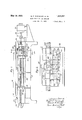
- Figure 1 is a front elevation of a rolling machine embodying my invention.
- Fig. 2 is a front elevation of the reciprocating carriage thereof.
- Fig. 3 is a. transverse sectional elevation taken on line 33 of Fig. 1.
- Fig. 4 is a transverse sectional elevation taken on line l4: of Fig. 1.
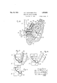
- FIG. 5 is a partial elevational view showing thestrip in place on a running board flange ready for the rolling operation.
- Fig. 6 is a partial elevational view illustrating the operation performed by the initial roll
- Fig. 7 is another partial elevational view illustrating the operation perform-ed by the finishing roll. 7
- the composite running board which, in this instance, constitutes the preformed body, comprises a sheet metal body 10 having depending marginal flanges, and a rubber tread 11 vulcanized to the top surface so as to extend down upon the depending front flange 12.
- This depending front flange is provided at its lower edge with a laterally off-set longitudinally extending flange or bead portion 13, against which an edge of the rubber'tread abuts.
- the rubber tread isvulcanized to the metal, so as to cover substantially the entire upper surface of the metal body, leaving uncovered the end and back flanges and the depending longitudinally extending bead or flange portion 13.
- a sheath in the form of a trim strip 14 is applied thereto.
- This trim strip may be made of any appropriate material, such as chromium plated zinc, and is secured 1n place by bending or crimping a portion thereof around the free edge of the flange or head portion 13 in the manner now to be described.
- the apparatus which we have devised for rapidly and uniformly applying the bead strips 1 1 to the flange or bead portions of the bodies, is provided with a frame 15 having longitudinallyextending bearing surfaces 16 and 17 which constitute ways for guiding and supporting the reciprocable carriage 18.
- This frame is also provided with longitudinally spaced brackets 19,'upon which the bed plate 20 is supported and secured.
- a horizontal work supporting platen or mandrel 21, and longitudinally spaced vertical work supporting brackets 22, are secured to this bed plate by any suitable means, such as the bolts 23.
- the platen 21 is provided with a longitudinally extending groove or recess 24 which is shaped to receive the flange or bead portion 13 of the running board, so as to form an anvil or mandrel for supporting the work during the rolling operations.
- the upstanding lugs 25 which are secured to the ends of the bed plate, extend above the platen and engage end portions of the running board and prevent endwise movement of the same.
- the vertical brackets 22 engage the rubber tread of the running board, and, together with the groove 24, hold the running board in the vertical position illustrated in Fig. 3 during the rolling operations.
- the trim strip is secured to the longitudinally extendingbead or flange portion 13 by bending a part of the strip around this portion, and for performing this bending operation the reciprocable carriage 18 is provided with a plurality of rolls. These rolls are arranged to form two sets, one for operating on a piece of work as the carriage is moved in one direction and the other set for operating on a piece of work when the carriage is moved in the opposite direction.
- the rolls 26 and 27 constitute one of these sets, and operate upon the work when the carriage is moved'toward the left-hand end of the machine, as viewed in Fig. 1.
- the rolls 28 and 29 constitute the Other setand operate upon, the work when the carriage is moved toward the right-hand end of the machine, as viewed in Fig. 1.
- the roll 30, which is interposed between the rolls 27 and 28,- is a finishing roll, and is common to both of these sets, that is to say, as the carriage moves toward the left this roll performs the finishing operation for the rolls 26 and 27, and when the carriage is moved toward the right this roll performs the finishing operation for the rolls 28 and 29.
- the rolls are carried by a mountin member 31, which is secured to the carriage in any suitable manner between the opposed pairs of lugs or abutment members 32 and 33.
- Set screws 34 extending through these lugs engage the laterally extending ears 35 of the mounting member, so that this member, and
- the rolls 26, 27, 28 and 29 are carried by spindles 36 which extend into openings provided in the mounting member, and which are rotatably supported by antifriction bearings 37 and 38arranged in those openings.
- the spindles 36 for these rolls are all substantially parallel to each other, and are arrangedto extend into the mounting member at substantiallv right angles to the plane of the carriage 18.
- the finishing roll 30 is also carried by the mounting member 31, but to prevent breakage of the apparatus or damage to the work, it is necessary to provide for movement of this finishing roll to compensate for irregularities occurring in the shape or dimensions of the running boards operated upon.
- the finishing roll 30 is roetatably supported upon a spindle 39, which is held in the movable mounting member 40 by means of the set screw 41.
- the mounting member 40 is pivotally secured to an anchor member 42 by means of the hinge pin 43.
- This anchor member is of such size and shape as to correspond with the size and shape of an opening provided in the mounting member 31, and is retained in this opening by means of the set screw 44.
- the carriage 18 may be reciprocated in the frame by any suitable means, such as the feed screw 49 which is supported at its ends by the bearings 50 and 51, and which is adapted to be rotated in opposite directions by the reversible electric motor 52 operatively connected thereto by the flexible coupling 53.
- suitable means such as the feed screw 49 which is supported at its ends by the bearings 50 and 51, and which is adapted to be rotated in opposite directions by the reversible electric motor 52 operatively connected thereto by the flexible coupling 53.
- limit switches 54 and 55 adjacent opposite ends of the frame.
- the cam 56 of the carriage engages the arm 57 of the limit swltch 54 and actuates the latter.
- the cam 56 engages the arm 58 of the limit switch 55 and actuates the latter.
- the engagement of the cam 56 with theswitch actuating arms 57 and 58 causes the circuit of the motor 52 to be opened at the proper time to allow the carriage to be brought to a stop at the end of its travel. Movement of these switch arms also alters the motor circuit, so that when the starting button is again pressed, the motor will ro tate in the reverse direction to move the carria e in the opposite direction.
- the bead or trim strip 14 is of the cross-sectional shape illustrated in Fig. 5 of the drawings, and preparatory to the rolling operations is hooked over the head or flange portion 13 with its free edge 59 extending substantially as shown in this figure.
- the running board, with the strip let loosely applied thereto, is placed in the rolling machine in the position illustrated in Figs. 1 and 3 of the drawings, and upon movement of the carriage toward the lefthand end of the machine, as seen in Fig. l, the roll 26 engages the upstanding flange portion 59 and deflects the same laterally to the position illustrated in full lines in Fig. 6.
- the roll 27 following immediately behind the roll 26 deflects the flange portion 59 to the position illustrated in Fig.
- a work support adapted to receive a body having a flange to which a metallic strip is to be applied
- a reciprocable carriage means for reciprocating said carriage, a series of rolls on said carriage for bending said strip around said flange and movable mounting.
- means for one of said (rolls, said mounting means comprising a pivot member on said carriage, a spindle rotatably supporting said one of said rolls, a holder for said spindle pivoted on said pivot member, spring means on said carriage arranged to cooperate with said holder for biasing said one roll toward the work, and adjusting means for regulating the ac tion of said spring.
- a work support adapted to receive a body having a portion to which a metallic member is to be applied, a car riage, means for causing relative traversing movement between said carriage and said body portion, a series of rolls on said carriage for progressively bending said member around said body portion and movable mounting means for one of said rolls, said mounting means comprising a pivot member on said carriage, a spindle ro-tatably supporting said one of said rolls, a holder for said spindle pivoted on said pivot member, and spring means on said carriage arranged to cooperate with said holder for biasing said one roll toward the work.
- a work support adapted to receive a boc y having a portion to which a metallic strip is to be applied
- a carriage means for causing relative traversing movement between said carriage and said body portion, a series of rolls for progressively bending said strip around said body portion.
- movable mounting'means on said carriage comprising a pivot member on said carriage, a spindle rotatably supporting said one of said rolls, and a holder for said spindle pivoted on said pivot member.
- a work support adapted to receive a body having a portion to which a metallic member is to be applied
- a carriage means for causing relative traversing movement between said carriage and said body po-rtion, a series of rolls for progressively bending said member around said body portion, movable mounting means on said carriage for one of said rolls, and means for yieldingly resisting movement of said mounting means.
- a work support adapted to receive a body having a portion to which a metallic member is to be applied, a carriage, means for causing relative traversing movement between said carriage and said body portion, a series of rolls for progressively bending said member around said body portion including a finishing roll, and movable mounting means on said carriage for said finishing roll said mounting means comprising a pivot member on said carriage, a spindle rotatably supporting said finishing roll, and a holder for said spindle pivoted on said pivot member.
- a work support adapted to receive a body having a portion to which a metallic member is to be applied, a carriage, means for causing relative traversing movement between said carriage and said body portion, a series of rolls for progressively bending said member around said flange including a finishing roll, movable mounting means on said carriage for said finishing roll, and means for yieldingly resisting movement of said mounting means.
- a machine for attaching metal binding strips to running board bodies including a mandrel adapted to be engaged by the running board portion to be operated upon and a positioning rest adjacent said mandrel, a movable carriage havin rolls for bending a binding strip around 'sai running board portion, and means for actuating said carriage to cause said rolls to traverse said running board portion.
- a. machine for attaching metal binding strips to running board bodies including a mandrel adapted to be engaged by the running board portion to be operated upon and a positioning rest adjacent said mandrel, a movable carriage having rolls for bending a binding strip around said running board portion, means for actuating said carriage to cause said rolls to traverse said running board portion, and means for movably supporting said carriage with the plane thereof in angularly disposed relation to the plane of the running board.
- actuating means for causing relative traversing movement between said rolls and said edge to be operated upon, and means for supporting said carriage with the plane thereof in inclined relation to the plane of the running board.
Landscapes
- Engineering & Computer Science (AREA)
- Mechanical Engineering (AREA)
- Bending Of Plates, Rods, And Pipes (AREA)
Description
May 16, 1933- G. F. CAVANAGH ET AL BEAD STRIP ROLLING MACHINE Filed Feb. 16, 1931 5 Sheets-Sheet l In vewificz a: 6'. fiwzai @630 y 1933. G. F. CAVANAGH ET AL 1,908,690
BEAQSTRIP ROLLING MACHINE Filed Feb. 16, 1931 3 Sheets-Sheet 2 May 16, 1933- G. F. CAVANAGH ET AL 1,908,690
BEAD STRIP ROLLING MACHINE Filed Feb. 16, 1931 3 Sheets-Sheet 5 l0 48 f8 P 4 l 45 9 I l 47 g 1 f l a 59 I 72 Z5 Patented May 16, 1833 GERALD F. CAVANAGH, OF CLEVELAND, AND EDMUND M. WINEGAR, 0F WILLOUGHBY,
OHIO, ASSIGNORS TO THE OHIO RUBBER COMPANY, OF CLEVELAND, OHIO, A COR- PORATION OF OHIO Application filed February 16, 1931.
This invention relates to rolling machines for working metal, and more particularly to a machine of this kind for applying sheathing or covering material, in the form of metal sheet or strip, to a flange or head portion of a body, such as a composite vehicle running board.
An object of this invention is to provide an improved rolling machine for rapidly and uniformly applying trimming or sheathing material to a preformed body.
Another object of this invention is to provide an improved rolling machine of the type mentioned, having means for applying metal strip to a flange or head portion of a body by a series of bending or forming operations.
A further object of this invention is to provide an improved rolling machine of the kind mentioned, having movable mounting means for the finishing roll.
The invention may be further briefly summarized as consisting in certain novel combinations and arrangements of parts hereinafter described and particularly set out in the appended claims.
In the accompanying sheets of drawings,
Figure 1 is a front elevation of a rolling machine embodying my invention.
Fig. 2 is a front elevation of the reciprocating carriage thereof.
Fig. 3 is a. transverse sectional elevation taken on line 33 of Fig. 1.
Fig. 4 is a transverse sectional elevation taken on line l4: of Fig. 1.
5 is a partial elevational view showing thestrip in place on a running board flange ready for the rolling operation.
Fig. 6 is a partial elevational view illustrating the operation performed by the initial roll, and
Fig. 7 is another partial elevational view illustrating the operation perform-ed by the finishing roll. 7
In the accompanying drawings to which detailed reference will presently be made, we have shown our invention embodied in a'rolling machine for rapidly and uniformly applying metallic trim or cover strip to bead or flange portions of preformed bodies. In
Serial No. 516,078.
describing our invention we have referred 1n particular to a composite vehicle running board of the form disclosed and claimed in United States Patent No. 1,784,781, issued December 9, 1930, but it should be understood that our invention may also be embodied in other apparatus for applying strips or sheets of trimming or sheathing material to bodies of various forms. I
Before proceeding with the detailed description of our improved rolling machine,
it is pointed out that the composite running board, which, in this instance, constitutes the preformed body, comprises a sheet metal body 10 having depending marginal flanges, and a rubber tread 11 vulcanized to the top surface so as to extend down upon the depending front flange 12. This depending front flange is provided at its lower edge with a laterally off-set longitudinally extending flange or bead portion 13, against which an edge of the rubber'tread abuts. In constructing this composite running board the rubber tread isvulcanized to the metal, so as to cover substantially the entire upper surface of the metal body, leaving uncovered the end and back flanges and the depending longitudinally extending bead or flange portion 13. To give this longitudinally extending bead or flange portion a wear-resisting, durable and decorative finish a sheath in the form of a trim strip 14, is applied thereto. This trim strip may be made of any appropriate material, such as chromium plated zinc, and is secured 1n place by bending or crimping a portion thereof around the free edge of the flange or head portion 13 in the manner now to be described. I
The apparatus which we have devised for rapidly and uniformly applying the bead strips 1 1 to the flange or bead portions of the bodies, is provided with a frame 15 having longitudinallyextending bearing surfaces 16 and 17 which constitute ways for guiding and supporting the reciprocable carriage 18. This frame is also provided with longitudinally spaced brackets 19,'upon which the bed plate 20 is supported and secured. A horizontal work supporting platen or mandrel 21, and longitudinally spaced vertical work supporting brackets 22, are secured to this bed plate by any suitable means, such as the bolts 23.
The platen 21 is provided with a longitudinally extending groove or recess 24 which is shaped to receive the flange or bead portion 13 of the running board, so as to form an anvil or mandrel for supporting the work during the rolling operations. At the ends of the platen which is of substantially the same length as the head or flange portion 13, the upstanding lugs 25 which are secured to the ends of the bed plate, extend above the platen and engage end portions of the running board and prevent endwise movement of the same. The vertical brackets 22 engage the rubber tread of the running board, and, together with the groove 24, hold the running board in the vertical position illustrated in Fig. 3 during the rolling operations.
The trim strip, as already stated, is secured to the longitudinally extendingbead or flange portion 13 by bending a part of the strip around this portion, and for performing this bending operation the reciprocable carriage 18 is provided with a plurality of rolls. These rolls are arranged to form two sets, one for operating on a piece of work as the carriage is moved in one direction and the other set for operating on a piece of work when the carriage is moved in the opposite direction. The rolls 26 and 27 constitute one of these sets, and operate upon the work when the carriage is moved'toward the left-hand end of the machine, as viewed in Fig. 1. The rolls 28 and 29 constitute the Other setand operate upon, the work when the carriage is moved toward the right-hand end of the machine, as viewed in Fig. 1. The roll 30, which is interposed between the rolls 27 and 28,- is a finishing roll, and is common to both of these sets, that is to say, as the carriage moves toward the left this roll performs the finishing operation for the rolls 26 and 27, and when the carriage is moved toward the right this roll performs the finishing operation for the rolls 28 and 29.
The rolls are carried by a mountin member 31, which is secured to the carriage in any suitable manner between the opposed pairs of lugs or abutment members 32 and 33. Set screws 34 extending through these lugs engage the laterally extending ears 35 of the mounting member, so that this member, and
the rolls carried thereby, may be adjusted vertically with respect to the platen 21. The rolls 26, 27, 28 and 29 are carried by spindles 36 which extend into openings provided in the mounting member, and which are rotatably supported by antifriction bearings 37 and 38arranged in those openings. The spindles 36 for these rolls are all substantially parallel to each other, and are arrangedto extend into the mounting member at substantiallv right angles to the plane of the carriage 18.
The finishing roll 30 is also carried by the mounting member 31, but to prevent breakage of the apparatus or damage to the work, it is necessary to provide for movement of this finishing roll to compensate for irregularities occurring in the shape or dimensions of the running boards operated upon. As shown in Fig. 4, the finishing roll 30 is roetatably supported upon a spindle 39, which is held in the movable mounting member 40 by means of the set screw 41. The mounting member 40 is pivotally secured to an anchor member 42 by means of the hinge pin 43. This anchor member is of such size and shape as to correspond with the size and shape of an opening provided in the mounting member 31, and is retained in this opening by means of the set screw 44. It will be seen that the arrangement just described will permit of arcuate movement of the mounting member 40, and of the finishing roll 30 carried thereby, about the hinge pin 43 as a center. To resist this movement of the finishing roll, we provide a boss 45 on the carriage having a plunger 46 therein which is pressed against the mounting member 40 by a coil spring 47. The characteristics of this spring are such that it will cause the roll 30 to be pressed against the work with sufiicient force for the roll to accomplish its desired function, but will permit slight yielding movement of the mounting member 40, and of the roll carried thereby, when running boards of irregular shape or size are encountered. The member 48 screwed into the boss 45 serves as a guide for the plunger 46 and also constitutes a means for adjusting the compression of the spring 47.
The carriage 18 may be reciprocated in the frame by any suitable means, such as the feed screw 49 which is supported at its ends by the bearings 50 and 51, and which is adapted to be rotated in opposite directions by the reversible electric motor 52 operatively connected thereto by the flexible coupling 53.
To limit the movement of the carriage 18, and to automatically stop the same when the rollers have traversed the work, we provide limit switches 54 and 55 adjacent opposite ends of the frame. As the carriage moves toward the left-hand end of the machine, as viewed in Fig. 1, the cam 56 of the carriage engages the arm 57 of the limit swltch 54 and actuates the latter. Likewise, as the carriage moves toward the right to its position illustrated in Fig. 1, the cam 56 engages the arm 58 of the limit switch 55 and actuates the latter. The engagement of the cam 56 with theswitch actuating arms 57 and 58, causes the circuit of the motor 52 to be opened at the proper time to allow the carriage to be brought to a stop at the end of its travel. Movement of these switch arms also alters the motor circuit, so that when the starting button is again pressed, the motor will ro tate in the reverse direction to move the carria e in the opposite direction.
fil its original form the bead or trim strip 14 is of the cross-sectional shape illustrated in Fig. 5 of the drawings, and preparatory to the rolling operations is hooked over the head or flange portion 13 with its free edge 59 extending substantially as shown in this figure. The running board, with the strip let loosely applied thereto, is placed in the rolling machine in the position illustrated in Figs. 1 and 3 of the drawings, and upon movement of the carriage toward the lefthand end of the machine, as seen in Fig. l, the roll 26 engages the upstanding flange portion 59 and deflects the same laterally to the position illustrated in full lines in Fig. 6. The roll 27 following immediately behind the roll 26 deflects the flange portion 59 to the position illustrated in Fig. 3, and the finishing roll 30, following the roll 27, crimps the flange portion 59 around the free edge of the head 13 by bending it to the po sition illustrated in Fig. 7 of the drawings, thereby securing the strip in place on the running board body.
From the construction of our machine, as illustrated in Figs. 3 and 4 of the drawings, it will be noted that the running board body to be operated upon is supported. upon the edge to which the binding strip is to be applied and with the plane of the running board in substantially vertical relation. It will also be noted that the bearing surfaces 16 and 17 of the carriage supporting structure are so arranged that the carriage is supported with the plane thereof in inclined relation to the plane of the running board being operated upon. With the various parts of the machine disposed in this arrangement we find that the running boards can be readily inserted and removed from the machine, and that by supporting the carriage in the inclined relation referred to, this member operates efliciently to perform its desired function.
It will now be readily seen that we have devised a rolling machine, whereby trim or sheathing material in sheet or strip form can be rapidly and uniformly applied to flange or head portions of preformed bodies, and moreover, it will be seen that we have provided a novel and efiicient form of mounting means for the finishing roll, so as to permit movement of this roll and thereby conipensate for irregularities in the shape or size of the bodies to be operated upon. It will also be understood that with the arrangement of limit switch means which we have pro vided, and by using a finishing roll common to two sets of operating rolls, rolling opera tions can be performed during each successive movement of the carriage.
While we have illustrated and described the apparatus of our invention, it should he understood, however, that we do not intend to limit ourselves to the precise details and arrangement of structure illustrated and described, but regard our invention as including such changes and modifications as do not involve a departure from the spirit of the invention and the scope of the appended claims.
Having thus described our invention what we claim is:
1. In apparatus of the character described the combination of a work support adapted to receive a body having a flange to which a metallic strip is to be applied, a reciprocable carriage, means for reciprocating said carriage, a series of rolls on said carriage for bending said strip around said flange and movable mounting. means for one of said (rolls, said mounting means comprising a pivot member on said carriage, a spindle rotatably supporting said one of said rolls, a holder for said spindle pivoted on said pivot member, spring means on said carriage arranged to cooperate with said holder for biasing said one roll toward the work, and adjusting means for regulating the ac tion of said spring.
2. In appa-ratus'of the character described the combination of a work support adapted to receive a body having a portion to which a metallic member is to be applied, a car riage, means for causing relative traversing movement between said carriage and said body portion, a series of rolls on said carriage for progressively bending said member around said body portion and movable mounting means for one of said rolls, said mounting means comprising a pivot member on said carriage, a spindle ro-tatably supporting said one of said rolls, a holder for said spindle pivoted on said pivot member, and spring means on said carriage arranged to cooperate with said holder for biasing said one roll toward the work.
3. In apparatus of the character described the combination of a work support adapted to receive a boc y having a portion to which a metallic strip is to be applied, a carriage, means for causing relative traversing movement between said carriage and said body portion, a series of rolls for progressively bending said strip around said body portion. and movable mounting'means on said carriage for 'one'of said rolls said mounting means comprising a pivot member on said carriage, a spindle rotatably supporting said one of said rolls, and a holder for said spindle pivoted on said pivot member.
4. In apparatus of the character described the combination of a work support adapted to receive a body having a portion to which a metallic member is to be applied, a carriage, means for causing relative traversing movement between said carriage and said body po-rtion, a series of rolls for progressively bending said member around said body portion, movable mounting means on said carriage for one of said rolls, and means for yieldingly resisting movement of said mounting means.
5. In apparatus of the character described the combination of a work support adapted to receive a body having a portion to which a metallic member is to be applied, a carriage, means for causing relative traversing movement between said carriage and said body portion, a series of rolls for progressively bending said member around said body portion including a finishing roll, and movable mounting means on said carriage for said finishing roll said mounting means comprising a pivot member on said carriage, a spindle rotatably supporting said finishing roll, and a holder for said spindle pivoted on said pivot member.
6. In apparatus of the character described the combination of a work support adapted to receive a body having a portion to which a metallic member is to be applied, a carriage, means for causing relative traversing movement between said carriage and said body portion, a series of rolls for progressively bending said member around said flange including a finishing roll, movable mounting means on said carriage for said finishing roll, and means for yieldingly resisting movement of said mounting means.
7. In a machine for attaching metal binding strips to running board bodies, the combination of means for supporting a running board including a mandrel adapted to be engaged by the running board portion to be operated upon and a positioning rest adjacent said mandrel, a movable carriage havin rolls for bending a binding strip around 'sai running board portion, and means for actuating said carriage to cause said rolls to traverse said running board portion.
8. In a. machine for attaching metal binding strips to running board bodies, the combination of means for supporting a running board including a mandrel adapted to be engaged by the running board portion to be operated upon and a positioning rest adjacent said mandrel, a movable carriage having rolls for bending a binding strip around said running board portion, means for actuating said carriage to cause said rolls to traverse said running board portion, and means for movably supporting said carriage with the plane thereof in angularly disposed relation to the plane of the running board.
9. In a machine for attaching metal binding strips to edge portions of running board bodies, the combination of means for supporting a running board in edgewise relation and upon the edge thereof to be operated upon, a carriage having rolls for bending a binding strip around said edge to be operated upon,
actuating means for causing relative traversing movement between said rolls and said edge to be operated upon, and means for supporting said carriage with the plane thereof in inclined relation to the plane of the running board.
In testimony whereof, we hereunto aflix our signatures.
GERALD F. CAVANAGH.
EDMUND M. vVIl TEGrAR-..
Priority Applications (1)
| Application Number | Priority Date | Filing Date | Title |
|---|---|---|---|
| US516078A US1908690A (en) | 1931-02-16 | 1931-02-16 | Bead strip rolling machine |
Applications Claiming Priority (1)
| Application Number | Priority Date | Filing Date | Title |
|---|---|---|---|
| US516078A US1908690A (en) | 1931-02-16 | 1931-02-16 | Bead strip rolling machine |
Publications (1)
| Publication Number | Publication Date |
|---|---|
| US1908690A true US1908690A (en) | 1933-05-16 |
Family
ID=24054036
Family Applications (1)
| Application Number | Title | Priority Date | Filing Date |
|---|---|---|---|
| US516078A Expired - Lifetime US1908690A (en) | 1931-02-16 | 1931-02-16 | Bead strip rolling machine |
Country Status (1)
| Country | Link |
|---|---|
| US (1) | US1908690A (en) |
-
1931
- 1931-02-16 US US516078A patent/US1908690A/en not_active Expired - Lifetime
Similar Documents
| Publication | Publication Date | Title |
|---|---|---|
| US1908690A (en) | Bead strip rolling machine | |
| CN107790824A (en) | A stainless steel trimming machine | |
| US1857832A (en) | Automatic buffing machine | |
| CN208895529U (en) | A kind of automobile electronic controller shell press-loading device | |
| US3185006A (en) | Method for trimming edges of sheets | |
| US3494253A (en) | Metallic strip milling machine | |
| DE19706712A1 (en) | Folding surface coverings over edges | |
| US2091749A (en) | Metalworking machine | |
| CN215998460U (en) | Pressing device and bending machine | |
| CN108747404B (en) | Full-automatic round brush support make-up machine | |
| CN219311488U (en) | Feeding transmission device of thicknesser | |
| US3800475A (en) | Machine for polishing a surface, particularly the surface of a spool flange | |
| US3535905A (en) | Rectilinear edge flanging tool for sheet metal workpieces | |
| US4608783A (en) | Feeler unit for positioning sheet glass processing tools | |
| JPS5838681A (en) | Welding device of roof for automobile | |
| US3033266A (en) | Stretch forming machine | |
| CN220128106U (en) | Tape splicing machine | |
| US3181322A (en) | Machine for smoothing band-saw blades | |
| US2158400A (en) | Metal forming working device | |
| CN113579109A (en) | A pressing device and bending machine | |
| US2235996A (en) | Blank cutting machine | |
| CN106623024A (en) | Automatic steel roll belt cleaning and compressing mechanism | |
| US686075A (en) | Feed mechanism for shears. | |
| CN116748429B (en) | A spring machine curve gauge slide mounting structure | |
| SU1292864A1 (en) | Apparatus for placing head end of strip to pinch rolls from coil |
Legal Events
| Date | Code | Title | Description |
|---|---|---|---|
| AS | Assignment |
Owner name: NEW CHAPTER, INC., VERMONT Free format text: CHANGE OF NAME;ASSIGNOR:NEW MOON EXTRACTS,INC.;REEL/FRAME:012043/0331 Effective date: 19950831 |