US1908585A - Floor mat - Google Patents
Floor mat Download PDFInfo
- Publication number
- US1908585A US1908585A US563349A US56334931A US1908585A US 1908585 A US1908585 A US 1908585A US 563349 A US563349 A US 563349A US 56334931 A US56334931 A US 56334931A US 1908585 A US1908585 A US 1908585A
- Authority
- US
- United States
- Prior art keywords
- links
- ridges
- link
- holes
- floor mat
- Prior art date
- Legal status (The legal status is an assumption and is not a legal conclusion. Google has not performed a legal analysis and makes no representation as to the accuracy of the status listed.)
- Expired - Lifetime
Links
- 239000012858 resilient material Substances 0.000 description 5
- 239000007787 solid Substances 0.000 description 5
- 238000010276 construction Methods 0.000 description 3
- 230000009471 action Effects 0.000 description 1
- 238000005336 cracking Methods 0.000 description 1
- 230000000694 effects Effects 0.000 description 1
- 230000002708 enhancing effect Effects 0.000 description 1
- 239000000463 material Substances 0.000 description 1
- 230000004048 modification Effects 0.000 description 1
- 238000012986 modification Methods 0.000 description 1
- 230000002035 prolonged effect Effects 0.000 description 1
- 230000008439 repair process Effects 0.000 description 1
Images
Classifications
-
- A—HUMAN NECESSITIES
- A47—FURNITURE; DOMESTIC ARTICLES OR APPLIANCES; COFFEE MILLS; SPICE MILLS; SUCTION CLEANERS IN GENERAL
- A47G—HOUSEHOLD OR TABLE EQUIPMENT
- A47G27/00—Floor fabrics; Fastenings therefor
- A47G27/02—Carpets; Stair runners; Bedside rugs; Foot mats
- A47G27/0212—Carpets; Stair runners; Bedside rugs; Foot mats to support or cushion
- A47G27/0218—Link mats
Definitions
- This invention relates to floor mats of the link. type, wherein the links are pivotally connected together in successivegrows and are composed of resilient material, such as 5 soft rubber, and it particularly relates to improvements in the form of link members disclosed in United States Letters Patent, No. 1,797,562, issued March 24th, 1931.
- link shown in said patent and heretofore extensively used commercially In the form of link shown in said patent and heretofore extensively used commercially,
- the object of this invention is to improve. the construction of such links, whereby to strengthen and materially prolong the life and wearing qualities thereof Without departing from the advantages incidentto the various features of construction of links of this character as defined in said patent, thus enhancing the practicability and commercial value thereof.
- 1 designates the links of a mat embodying the invention, which links are a resilient material such as soft rubber
- 2 are'the pivot rods which pivotally connect the successive rows of links with the links of such rows arranged in alternating relation, as is common with link mats of. this character.
- Each link 1 is provided transversely through each end with a hole 3for receiving a pivot member 2, these holes preferably being larger in diameter than the diameters ofthe pivot members to, facilitate resiliency.
- the link is also provided transversely therethrough between the holes 3 and substantially parallel therewith, with one or more holes 4, in the present instance two innumber, to facilitate resiliency of the link.
- Each tread surface of the link is provided with a plurality of cross ridges 5, which par.- allel the holes 3 and 4, and alternate therewith.
- These ridges correspond in number to the solid portions between the several holes and are arranged in opposing pairs, so that a pressure on one is distributed directly to an opposed supporting surface through the opposed ridge at the opposite side of the link and throu h the interposed solid portion of the link. t is thus apparent that the lines of pressure between opposing ridges are through solid portions of the link and alternate with the holes.
- the ridges are all disposed within the area between the holes 3 and are preferably substantially of the crosssectional V-form shown.
- both the provision of the ri ges, and the provision of the holes through the links in substantially parallel relation to the ridges is important and that by disposing the ridges in such relation to the holes that the lines of pressure between opposing ridges is through the solid ortions of the link members between the oles, or alternate with the holes, that the bers of resilient material, each having a plurality of pairs of opposing ridges on the top is not limited to any s ecific. construction
- a plurality of link members of resilient material each having a pivot rod receivin hole near each end and one or more holes t erebetween, and each having a plurality of cross ridges on the top and bottom surfaces thereof in parallel relation to and alternating with said holes so that the pressure lines of opposed ridges are through solid portions of the members between the holes.
Landscapes
- Carpets (AREA)
Description
May 9, 1933.
Filed Sept. 17, 1931 gwve'ntot auomqw Patented May 9, 1933 UNITED STATES] "PATENT I OFFICE FRANCIS M. WILLIAMS AND mm. w. coins, or romano, onio, assrenonsor rwo- THIRDS TO THE COMMERCE GUARDIAN BANK, OF TOLEDO, OHIO, A CORPORATION 0]" 01110, rnos'rma noon. m'r
This invention relates to floor mats of the link. type, wherein the links are pivotally connected together in successivegrows and are composed of resilient material, such as 5 soft rubber, and it particularly relates to improvements in the form of link members disclosed in United States Letters Patent, No. 1,797,562, issued March 24th, 1931. In the form of link shown in said patent and heretofore extensively used commercially,
considerable difliculty and repair expense has been encountered due to the material breaking down and cracking opposite the openings provided through the links for receiving the pivot wires and for enhanolng the resiliency and cushion effect of the links.
The object of this invention is to improve. the construction of such links, whereby to strengthen and materially prolong the life and wearing qualities thereof Without departing from the advantages incidentto the various features of construction of links of this character as defined in said patent, thus enhancing the practicability and commercial value thereof.
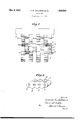
The invention is fully described in the following specification, and one embodiment thereof illustrated in the accompanying drawing, in Which Figure 1 is a fragmentary view of a mat made up of links embodying the invention, and Fig. 2 is an enlarged perspective view of one of the links.
In links of the character described, it is desirable, as defined in said patent, to provide the tread surfaces with transverse ridges and to provide transverse openings through the links in substantially parallel relation to the ridges for the purpose of receiving the pivot or connecting members for the links and to increase the cushion action or resiliency of the links. It is found, however, that a materially better' and stronger link is provided, and breaking down of the rubber or other resilient material comprising the links redncedtoa minimum, and the life and wearing qualities of the links materially prolonged if the ridges, instead of being disposed directly opposite openings through the links, as illustrated insaid patent, are dissure lines betweenopposing ridges.
In the drawing, 1 designates the links of a mat embodying the invention, which links are a resilient material such as soft rubber, and 2 are'the pivot rods which pivotally connect the successive rows of links with the links of such rows arranged in alternating relation, as is common with link mats of. this character.
Each link 1 is provided transversely through each end with a hole 3for receiving a pivot member 2, these holes preferably being larger in diameter than the diameters ofthe pivot members to, facilitate resiliency. The link is also provided transversely therethrough between the holes 3 and substantially parallel therewith, with one or more holes 4, in the present instance two innumber, to facilitate resiliency of the link.
Each tread surface of the link is provided with a plurality of cross ridges 5, which par.- allel the holes 3 and 4, and alternate therewith. These ridges correspond in number to the solid portions between the several holes and are arranged in opposing pairs, so that a pressure on one is distributed directly to an opposed supporting surface through the opposed ridge at the opposite side of the link and throu h the interposed solid portion of the link. t is thus apparent that the lines of pressure between opposing ridges are through solid portions of the link and alternate with the holes. The ridges are all disposed within the area between the holes 3 and are preferably substantially of the crosssectional V-form shown.
It is found in ractice that both the provision of the ri ges, and the provision of the holes through the links in substantially parallel relation to the ridges, is important and that by disposing the ridges in such relation to the holes that the lines of pressure between opposing ridges is through the solid ortions of the link members between the oles, or alternate with the holes, that the bers of resilient material, each having a plurality of pairs of opposing ridges on the top is not limited to any s ecific. construction,
arran ement or form 0 the parts, as it is capab e of various modifications and changes without departing from the spirit of the claims.
Having thus described our invention, what we claim as new and desire to secure by United States Letters Patent is: I
1. In a floor mat, a plurality of link memand bottom surfaces thereof, and each having a plurality of holes therethrough, substantially paralleling the ridges and alternating with the pressure lines of opposing ridges.
2. In a floor mat, a plurality of link members of resilient material, each having a pivot rod receivin hole near each end and one or more holes t erebetween, and each having a plurality of cross ridges on the top and bottom surfaces thereof in parallel relation to and alternating with said holes so that the pressure lines of opposed ridges are through solid portions of the members between the holes.
In testimony whereof we have hereunto signed our names to. this specification.
FRANCIS M. WILLIAMS. EARL W. COBLE.
Priority Applications (1)
| Application Number | Priority Date | Filing Date | Title |
|---|---|---|---|
| US563349A US1908585A (en) | 1931-09-17 | 1931-09-17 | Floor mat |
Applications Claiming Priority (1)
| Application Number | Priority Date | Filing Date | Title |
|---|---|---|---|
| US563349A US1908585A (en) | 1931-09-17 | 1931-09-17 | Floor mat |
Publications (1)
| Publication Number | Publication Date |
|---|---|
| US1908585A true US1908585A (en) | 1933-05-09 |
Family
ID=24250155
Family Applications (1)
| Application Number | Title | Priority Date | Filing Date |
|---|---|---|---|
| US563349A Expired - Lifetime US1908585A (en) | 1931-09-17 | 1931-09-17 | Floor mat |
Country Status (1)
| Country | Link |
|---|---|
| US (1) | US1908585A (en) |
Cited By (3)
| Publication number | Priority date | Publication date | Assignee | Title |
|---|---|---|---|---|
| US2487027A (en) * | 1943-06-12 | 1949-11-01 | Rubbercraft Corp | Floor mat |
| US3015136A (en) * | 1957-10-17 | 1962-01-02 | Pawling Rubber Corp | Resilient mat structure |
| US20240149840A1 (en) * | 2019-10-10 | 2024-05-09 | Rubberform Recycled Products, Llc | Trackout mat |
-
1931
- 1931-09-17 US US563349A patent/US1908585A/en not_active Expired - Lifetime
Cited By (3)
| Publication number | Priority date | Publication date | Assignee | Title |
|---|---|---|---|---|
| US2487027A (en) * | 1943-06-12 | 1949-11-01 | Rubbercraft Corp | Floor mat |
| US3015136A (en) * | 1957-10-17 | 1962-01-02 | Pawling Rubber Corp | Resilient mat structure |
| US20240149840A1 (en) * | 2019-10-10 | 2024-05-09 | Rubberform Recycled Products, Llc | Trackout mat |
Similar Documents
| Publication | Publication Date | Title |
|---|---|---|
| US2322193A (en) | Cushion | |
| US3015136A (en) | Resilient mat structure | |
| US1612024A (en) | Belt | |
| US2224788A (en) | Brush | |
| US1908585A (en) | Floor mat | |
| US2001855A (en) | India-rubber spring | |
| US1748158A (en) | Flexible mandrel | |
| US2388927A (en) | Link mat | |
| US2668711A (en) | Golf tee having ball supporting fibers | |
| US2538443A (en) | Railway sleeper | |
| US2242731A (en) | Spring structure | |
| US2768674A (en) | Spring suspension for rocking chairs | |
| US2077901A (en) | Articulated floor mat | |
| US2629430A (en) | Zigzag spring cushion construction having a base and top layer of springs | |
| US746722A (en) | Matting. | |
| US1922001A (en) | Spring structure | |
| US1810191A (en) | Nonskid tire chain | |
| US1992884A (en) | Fabric | |
| US2111053A (en) | Belt fastener for side driving or v-belts | |
| US1925734A (en) | Floor mat | |
| US3457572A (en) | Latch-loc construction | |
| US977789A (en) | Mat. | |
| US1465550A (en) | Mat | |
| US1533019A (en) | Guy coupler for masts | |
| US1544914A (en) | Mat |