US1908578A - Apparatus for conveying and depositing cementitious material - Google Patents
Apparatus for conveying and depositing cementitious material Download PDFInfo
- Publication number
- US1908578A US1908578A US417633A US41763329A US1908578A US 1908578 A US1908578 A US 1908578A US 417633 A US417633 A US 417633A US 41763329 A US41763329 A US 41763329A US 1908578 A US1908578 A US 1908578A
- Authority
- US
- United States
- Prior art keywords
- conduit
- tromba
- air
- injector
- pressure
- Prior art date
- Legal status (The legal status is an assumption and is not a legal conclusion. Google has not performed a legal analysis and makes no representation as to the accuracy of the status listed.)
- Expired - Lifetime
Links
- 239000000463 material Substances 0.000 title description 20
- 238000000151 deposition Methods 0.000 title description 3
- 241001080126 Tromba Species 0.000 description 25
- 239000004568 cement Substances 0.000 description 8
- 238000010276 construction Methods 0.000 description 4
- 239000000203 mixture Substances 0.000 description 4
- 238000000034 method Methods 0.000 description 3
- XLYOFNOQVPJJNP-UHFFFAOYSA-N water Substances O XLYOFNOQVPJJNP-UHFFFAOYSA-N 0.000 description 3
- 241000239290 Araneae Species 0.000 description 1
- 230000033228 biological regulation Effects 0.000 description 1
- 238000004140 cleaning Methods 0.000 description 1
- 238000004891 communication Methods 0.000 description 1
- 230000000887 hydrating effect Effects 0.000 description 1
- 238000003780 insertion Methods 0.000 description 1
- 230000037431 insertion Effects 0.000 description 1
- 210000002445 nipple Anatomy 0.000 description 1
- 230000001105 regulatory effect Effects 0.000 description 1
- 239000004576 sand Substances 0.000 description 1
Images

Classifications
-
- B—PERFORMING OPERATIONS; TRANSPORTING
- B65—CONVEYING; PACKING; STORING; HANDLING THIN OR FILAMENTARY MATERIAL
- B65G—TRANSPORT OR STORAGE DEVICES, e.g. CONVEYORS FOR LOADING OR TIPPING, SHOP CONVEYOR SYSTEMS OR PNEUMATIC TUBE CONVEYORS
- B65G53/00—Conveying materials in bulk through troughs, pipes or tubes by floating the materials or by flow of gas, liquid or foam
- B65G53/34—Details
- B65G53/40—Feeding or discharging devices
- B65G53/46—Gates or sluices, e.g. rotary wheels
- B65G53/4608—Turnable elements, e.g. rotary wheels with pockets or passages for material
- B65G53/4616—Turnable elements, e.g. rotary wheels with pockets or passages for material with axis of turning parallel to flow
Definitions
- This invention has to do with the pneumatic conveyance of materials in pipes, conduits or the like, and ismore particularly related to the conveyance of finely divided ma- 5 terial in conduits by means of air (or other suitable gas) under considerable pressure.
- the method and apparatus contemplated by this invention have been developed especially for use in mixing, conveying and deposit- 1 1 ing cementitious or plastic material and while this particular application of themvention commonly known as a cement gun system will be used, in the following dc.
- this invention is adapted for use in the conveyance of material other than cement mixtures, such as sawdust, shavings, grain,-or the like;
- the apparatuscommonly employed in ce ment gun practice comprises what is ordinarily known as a gun which is connected with a conduit having a nozzle at its outer end.
- the general construction of the system contemplated by this invention comprises a gun embodying the principal of an injector which is constructed in a manner suchthat air at atmospheric pressure is drawn into'the 40 introduced into the stream of materialflow ing through the conduit.
- injectors which will be hereinafter referred to as relay injectors, embody the jet and tromba principle, arranged so that the tromba is effective to produce suction in that region of the conduit which is behind the injector;
- the primary object is to produce a system of the class described in which a comparatively small volume of gas compressed to a very high pressure maybe used to convey large quantities of material overany predetermined distance.
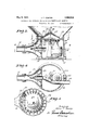
- F ig. 1 is an elevational view showing a cement gun system of the class described
- F ig..2 is a sectional elevation of the injector type of gun shown in Fig. 1, V
- Fig. 3 is a plan section taken substantially in a plane represented by line 33 in Fig. 2,
- Fig.4 is a plan section taken substantially in a plane represented by line 44 in Fig. 2
- Fig. 5 is a plan section of a relay injector taken in the plane represented by the line 5 5 of Fig. 1,
- Fig. 6 is a sectional elevation of a modified form of relay injector.
- reference numeral 11 indicates what will be hereinafter referred to as an injector gun by means of which a cement mixture or other suitable material is fed through a conduit 12 to anozzle 13.
- the conduit12 is made up of a plurality of sections indicated at 12a, 12b and 120. These sections increase in diameter in the order named andrelay injectors indicated by reference numerals 14 and 14a are interposed between the various conduit sections.
- Fig. 2 wherein the gun 11 is shown as comprising a tromba 15 which is supported upon a suitable base member 16 and has mounted therein an injector 17.
- the injector 17 is in internal communication with an'air or gas line 18 from which compressed air or gas is directed through the jet and into the tromba from a compressor (not shown).
- the back of the tromba 15. is provided with an apertured cover plate 19 having a damper 20 by means of which the supply of atmospheric air drawn into the tromba may be regulated.
- the material to be conveyed in the system is contained within a hopper 21 which is supported by the open top portion of the tromba 13 and a standard or bracket 22.
- the bottom 23 of the hopper is provided with an opening 24 which is immediately above the top opening in the tromba and a feed .
- wheel 25 is mounted on the base of the hopper and is adapted to receiverotation through a shaft pits periphery a plurality of teeth 34 which carry the material in the hopper beneath a plate 35 mounted above the periphery of the wheel over the aperture 24 which leads into the tromba.
- the hopper may also be provided with an adjustable gate 36, adapted for use in cleaning the wheel.
- Fig. 5 The details in the construction ofthe relay injector units are best illustrated in Fig. 5 where the unit 14 is shown ascomprising a tromba 40 having a forwardly tapered end portion 41 which is adaptedfor attachment to the rearrend of the conduit section 126.
- The. rear end portion of the tromba 40 is connected by means of a spider 42*with the front end portion 43 of a rearwardly'tapered collar 44.
- the rearend portion of thecollar 44 is adapted for attachment to the front end of-the conduit section 12m v
- a nozzle 45 is mounted in the tromba 4O sothat a stream of.
- the nozzle 45 is made in the form of a shell comprising a front section 47 anda' rear section 48.
- This shell may be. supported in the tromba in any suitable manner such' as by means of a plurality of thin brackets 49, and for the most eflicient operation of this unit I consider it preferableto formtheshell in.a manner suchthatthe cross sectional area between the outer surface'of the forward section 47 and the inner surface of that portion'of the tromba .to which it is adjacent, is substantially the same at all points.
- the'outer surface of the rear portion 48 is similarly arranged with respect to the inner surface of the collar 44. 7
- al 13 may be any well known type of nozzle but'is shown as comprising a nozzle of the typeshown and described in my copending application Serial No.417,950, filed January 52,1930, and comprises an inner nozzle 50a mounted in' aw'ater ring 51 and extending into the throat ofa tromba member'52' which has an enlarged funnel-like outlet, opening 53.
- This nozzle 13 is designed to draw atmospheric air into a stream of mixed concrete ejected from the inner nozzle 50a and to thereby decrease the velocity of the stream and consequently reduce the rebound at the surface of application.
- the hopper 21 is first filled with a sand mixture. (It is to be understood, of course, that a screw conveyor or equivalent structure, may be substituted for the hopper 21.) Compressed air is then admitted to the injector 17 and the rotation of the feed wheel 25 is started. The damper 20 is then adjusted so that the quantity of atmospheric air drawn into the tromba is sufficient to materially reduce the effective pressure of the compressed 7 air at the outlet of the tromba 15 and to consequently greatly increase the volume of air which is injected into the conduit with the cement mixture. The quantity of. air delivered into the relay injectors is adjusted so that the velocity of the material passing through the entire system is maintained substantially constant. The water for hydrating the cement is delivered to the water ring through the water conduit indicated by reference numeral 54:.
- the modified form of relay injector 14 shown in Fig. 6 embodies a tapered shell 56 which receives a flared nozzle or nipple 57 the outer end 58 of which is attached to a conduit section 12a.
- the outlet end of the shell 56 is attached to a conduit section 12?).
- a conduit composed of sections, each of said sections being of larger internal diameter than the preceding adjoining section; means interposed between adjacent sections for admitting gas under pressure into said conduit; and means associated with said first mentioned means operable to admit controllable amounts of atmospheric air into said conduit.
- a conveying system of the class described embodying: a tromba; a nozzle in said tromba; means for delivering material to be conveyed into said tromba; means for delivering gas under pressure to said nozzle to form a gas jet; a conduit at the outlet of said tromba for receiving the material proj ected therefrom by said jet; a relay injector in said conduit in spaced relation with the outlet of said tromba; a relay tromba asso-
Landscapes
- Engineering & Computer Science (AREA)
- Mechanical Engineering (AREA)
- On-Site Construction Work That Accompanies The Preparation And Application Of Concrete (AREA)
- Nozzles (AREA)
Description
y 1933- .1. T. VAWTER 8, v
APPARATUS FOR CONVEYING AND DEPOSITING CEMENTITIOUS MATERIAL Filed Dec. 31, 1929 2 Sheets-Sheet l figz Hzfarvey May 9, 1933. J T. v w 1,908,578
APPARATUS FOR CONVEYING AND DEPOSITING CEMENTITIOUS MATERIAL Filed Dec. 31, 1929 2 Sheets-Sheet 2 170677 T Vawfe/ Z MM Patented May 9, 1933 UNITED STATES JOHN T. VAWTER, or LOS ANGELES, oAnIronNiA APPARATUS FOR CONVEYING ANn nnrosrtrme oEME 'rrrroUs MATERIAL Application filed December e1, 1929." Serial no. 417,633.
This invention has to do with the pneumatic conveyance of materials in pipes, conduits or the like, and ismore particularly related to the conveyance of finely divided ma- 5 terial in conduits by means of air (or other suitable gas) under considerable pressure. The method and apparatus contemplated by this invention have been developed especially for use in mixing, conveying and deposit- 1 1 ing cementitious or plastic material and while this particular application of themvention commonly known as a cement gun system will be used, in the following dc.
scription, it is to be understood that this invention is adapted for use in the conveyance of material other than cement mixtures, such as sawdust, shavings, grain,-or the like;
The apparatuscommonly employed in ce ment gun practice comprises what is ordinarily known as a gun which is connected with a conduit having a nozzle at its outer end. The general construction of the system contemplated by this invention, comprises a gun embodying the principal of an injector which is constructed in a manner suchthat air at atmospheric pressure is drawn into'the 40 introduced into the stream of materialflow ing through the conduit. These injectors, which will be hereinafter referred to as relay injectors, embody the jet and tromba principle, arranged so that the tromba is effective to produce suction in that region of the conduit which is behind the injector;
It is well known to those familiar with the art, that the pressure of the gas at the inlet of the conduit in a system of thischaracter can neverbe less than the internal resistance of the conduit. Further, that the initial velocity of the gas at theinlet must be sufiicient to start and accelerate the material to be conveyed therethrough; It will be seen therefore'that when the resistance of the conduit is increasechas:Wouldbe effected by increasing its length there must be a corresponding increasein pressure to eilectthe conveyance: of material therethrough." It will also be apparent that with a fixed ca- 0 pacity'source of compressed gas this increase in pressure is attended by a proportional decrease in volume and that the decrease in: volume, the. cross-sectional area of the conduit remaining constant, results in a de- 05 crease-invelocity. Consequently, it has always been necessary heretofore in overcom ing internal resistance in conduits, to increaseboth the. pressure and the volume of the :conveyin'g medium. This requires the 7! use of extremely large compressor units which are expensive and difficult to move from place to place.
The primary object, contemplated by this invention, is to produce a system of the class described in which a comparatively small volume of gas compressed to a very high pressure maybe used to convey large quantities of material overany predetermined distance. v
, v so I In the injector type ofgun, referred to above, and which'will .be more fully de scribed later ;in the specification, the pressure of the air'entering the conduit system at the point of intake is reduced and the energy liberated by the reduction of pressure is utilized in drawing in and compressing additionalatmospheric air. The volume'of driving .air is. therefore materially increased, first by the expansion incident to the released pressure of the air coming from the compressor and, second'by the drawing in of additional air. This increase in volume is naturally attended, within the conduit, by an increase of velocity which admits an increase in the supply of material to be conveyed in .the conduit." This reduction of pressure, at the intake, is made possible by the removal ofa portion of the line resistanceahead of the. intake which is accomplished by the insertion of the relay injectors referred to above.
From this construction, it will be seen that a comparatively small volume of air under the highest pressure, economically obtainable, may be introduced at the gun and at the various relay injectors to convey a quantity of material over a distance which would, with the ordinary cement gun system, require a much larger volume of compressed air than is employed in the'system contemplated, by this invention.
Other advantages of this invention, to gether with further objects attending its development will be best understood from the following description in the accompanying drawings in which: Y f
F ig. 1 is an elevational view showing a cement gun system of the class described,
F ig..2 is a sectional elevation of the injector type of gun shown in Fig. 1, V
Fig. 3 is a plan section taken substantially in a plane represented by line 33 in Fig. 2,
Fig.4 is a plan section taken substantially in a plane represented by line 44 in Fig. 2, Fig. 5 is a plan section of a relay injector taken in the plane represented by the line 5 5 of Fig. 1,
Fig. 6 is a sectional elevation of a modified form of relay injector.
More particularly describing the invention asrherein illustrated, reference numeral 11 indicates what will be hereinafter referred to as an injector gun by means of which a cement mixture or other suitable material is fed through a conduit 12 to anozzle 13. The conduit12is made up of a plurality of sections indicated at 12a, 12b and 120. These sections increase in diameter in the order named andrelay injectors indicated by reference numerals 14 and 14a are interposed between the various conduit sections.
The details in the construction of a preferred form of gun are. best illustrated in Fig. 2 wherein the gun 11 is shown as comprising a tromba 15 which is supported upon a suitable base member 16 and has mounted therein an injector 17. The injector 17 is in internal communication with an'air or gas line 18 from which compressed air or gas is directed through the jet and into the tromba from a compressor (not shown). The back of the tromba 15. is provided with an apertured cover plate 19 having a damper 20 by means of which the supply of atmospheric air drawn into the tromba may be regulated. The material to be conveyed in the system is contained within a hopper 21 which is supported by the open top portion of the tromba 13 and a standard or bracket 22. The bottom 23 of the hopper is provided with an opening 24 which is immediately above the top opening in the tromba and a feed .wheel 25 is mounted on the base of the hopper and is adapted to receiverotation through a shaft pits periphery a plurality of teeth 34 which carry the material in the hopper beneath a plate 35 mounted above the periphery of the wheel over the aperture 24 which leads into the tromba. The hopper may also be provided with an adjustable gate 36, adapted for use in cleaning the wheel.
7 The details in the construction ofthe relay injector units are best illustrated in Fig. 5 where the unit 14 is shown ascomprising a tromba 40 having a forwardly tapered end portion 41 which is adaptedfor attachment to the rearrend of the conduit section 126.
The. rear end portion of the tromba 40 is connected by means of a spider 42*with the front end portion 43 of a rearwardly'tapered collar 44. The rearend portion of thecollar 44 is adapted for attachment to the front end of-the conduit section 12m v A nozzle 45 is mounted in the tromba 4O sothat a stream of.
gas under pressure entering: the nozzle through the pipe 46 is directed-into the stream of material flowing through the conduit in the direction of thearrows A and A The nozzle 45 is made in the form of a shell comprising a front section 47 anda' rear section 48. This shell may be. supported in the tromba in any suitable manner such' as by means of a plurality of thin brackets 49, and for the most eflicient operation of this unit I consider it preferableto formtheshell in.a manner suchthatthe cross sectional area between the outer surface'of the forward section 47 and the inner surface of that portion'of the tromba .to which it is adjacent, is substantially the same at all points. Likewise the'outer surface of the rear portion 48 is similarly arranged with respect to the inner surface of the collar 44. 7
For the purpose of providing an additional regulation in the quantity of air passing through the conduitsystem I provide the rear; end of the tromba 40 with an adjustable damper 49. The damper is shown as being slidably mounted between annular channels 50 and 50 which are'formed on the inner surward outer'edge of the collar 44.
face of the tromba member 40 and the f or- The nozzle indicated by reference numer.
al 13 may be any well known type of nozzle but'is shown as comprising a nozzle of the typeshown and described in my copending application Serial No.417,950, filed January 52,1930, and comprises an inner nozzle 50a mounted in' aw'ater ring 51 and extending into the throat ofa tromba member'52' which has an enlarged funnel-like outlet, opening 53. This nozzle 13 is designed to draw atmospheric air into a stream of mixed concrete ejected from the inner nozzle 50a and to thereby decrease the velocity of the stream and consequently reduce the rebound at the surface of application.
In the operation of this'device as a cement gun, the hopper 21 is first filled with a sand mixture. (It is to be understood, of course, that a screw conveyor or equivalent structure, may be substituted for the hopper 21.) Compressed air is then admitted to the injector 17 and the rotation of the feed wheel 25 is started. The damper 20 is then adjusted so that the quantity of atmospheric air drawn into the tromba is sufficient to materially reduce the effective pressure of the compressed 7 air at the outlet of the tromba 15 and to consequently greatly increase the volume of air which is injected into the conduit with the cement mixture. The quantity of. air delivered into the relay injectors is adjusted so that the velocity of the material passing through the entire system is maintained substantially constant. The water for hydrating the cement is delivered to the water ring through the water conduit indicated by reference numeral 54:.
The modified form of relay injector 14 shown in Fig. 6 embodies a tapered shell 56 which receives a flared nozzle or nipple 57 the outer end 58 of which is attached to a conduit section 12a. The outlet end of the shell 56 is attached to a conduit section 12?).
In the operation of this device, air under pressure is introduced into the shell at 59 and in passing through the throat section 60. of the shell, assists in drawing the material through the conduit 12a, and in advancing same through conduit 12?).
From the foregoing detailed description of the apparatus, it should be apparent that the objects and advantages of the process, as set forth in the forepart of the specification are means interposed between adjacent sections for admitting gas under pressure into said conduit; and means associated with said first mentioned means operable to admit atmospheric air into said conduit.
3. In a conveyor system of the class described: a conduit composed of sections, each of said sections being of larger internal diameter than the preceding adjoining section; means interposed between adjacent sections for admitting gas under pressure into said conduit; and means associated with said first mentioned means operable to admit controllable amounts of atmospheric air into said conduit.
In testimony whereof, I have hereunto set my hand at Los Angeles, California, this 18th day of December, 1929.
JOHN'T. VAWTER.
efiiciently accomplished. It is to be underv stood however, that while I have herein described and illustrated one preferred form of apparatus and one advantageous application of the process contemplated by this invention, that the invention is not limited to the precise details of'the above description, but includes within its scope whatever changes fairly come within the spirit of the appended claims.
I claim as my invention:
1. A conveying system of the class described embodying: a tromba; a nozzle in said tromba; means for delivering material to be conveyed into said tromba; means for delivering gas under pressure to said nozzle to form a gas jet; a conduit at the outlet of said tromba for receiving the material proj ected therefrom by said jet; a relay injector in said conduit in spaced relation with the outlet of said tromba; a relay tromba asso-
Priority Applications (1)
| Application Number | Priority Date | Filing Date | Title |
|---|---|---|---|
| US417633A US1908578A (en) | 1929-12-31 | 1929-12-31 | Apparatus for conveying and depositing cementitious material |
Applications Claiming Priority (1)
| Application Number | Priority Date | Filing Date | Title |
|---|---|---|---|
| US417633A US1908578A (en) | 1929-12-31 | 1929-12-31 | Apparatus for conveying and depositing cementitious material |
Publications (1)
| Publication Number | Publication Date |
|---|---|
| US1908578A true US1908578A (en) | 1933-05-09 |
Family
ID=23654780
Family Applications (1)
| Application Number | Title | Priority Date | Filing Date |
|---|---|---|---|
| US417633A Expired - Lifetime US1908578A (en) | 1929-12-31 | 1929-12-31 | Apparatus for conveying and depositing cementitious material |
Country Status (1)
| Country | Link |
|---|---|
| US (1) | US1908578A (en) |
Cited By (3)
| Publication number | Priority date | Publication date | Assignee | Title |
|---|---|---|---|---|
| US2444900A (en) * | 1943-04-21 | 1948-07-06 | Linde Air Prod Co | Blowpipe apparatus |
| US2645529A (en) * | 1951-01-02 | 1953-07-14 | Alexander F Szymborski | Measuring device for spray applicators in prevention of offset and the like |
| US5190415A (en) * | 1991-09-03 | 1993-03-02 | Ingersoll-Rand Company | Flow induced feed collector and transporter apparatus |
-
1929
- 1929-12-31 US US417633A patent/US1908578A/en not_active Expired - Lifetime
Cited By (3)
| Publication number | Priority date | Publication date | Assignee | Title |
|---|---|---|---|---|
| US2444900A (en) * | 1943-04-21 | 1948-07-06 | Linde Air Prod Co | Blowpipe apparatus |
| US2645529A (en) * | 1951-01-02 | 1953-07-14 | Alexander F Szymborski | Measuring device for spray applicators in prevention of offset and the like |
| US5190415A (en) * | 1991-09-03 | 1993-03-02 | Ingersoll-Rand Company | Flow induced feed collector and transporter apparatus |
Similar Documents
| Publication | Publication Date | Title |
|---|---|---|
| US4116491A (en) | Tubular pneumatic conveyor pipeline | |
| US5718539A (en) | Boundary air/laminar flow conveying system with air reduction cone | |
| US3212217A (en) | Cleaning device | |
| US2508766A (en) | Device for increasing the efficiency of sandblast gun operating by means of compressed air | |
| US2614892A (en) | Air flow conveyer | |
| US4500228A (en) | Granular material pneumatic transport apparatus | |
| US2355774A (en) | Apparatus for conveying pulverized material | |
| US4583329A (en) | High pressure jets | |
| US3099496A (en) | Pump for imparting movement to dry pulverulent material | |
| US2161553A (en) | Means of conveying and mixing comminuted material | |
| US2303810A (en) | Apparatus for depositing materials | |
| US3085834A (en) | Material spraying apparatus | |
| US1908578A (en) | Apparatus for conveying and depositing cementitious material | |
| GB1276030A (en) | Method of and apparatus for dispersing particulate materials in a liquid | |
| CA1260715A (en) | Feeding abrasive material | |
| US1506089A (en) | Concrete mixer and conveyer | |
| US2413293A (en) | Aggregate measurer and feeder | |
| US2799540A (en) | Log conveying | |
| JPH0475918A (en) | pneumatic transport equipment | |
| US2213640A (en) | Plastic material mixing device | |
| US4212566A (en) | Rotary feeder for solid particle injection into pressurized fluid system | |
| US4557632A (en) | Compacting apparatus | |
| US2835482A (en) | Cement applying machine | |
| GB1214322A (en) | Fluid mixing, moving and a tomizing methods and apparatus | |
| SU463602A1 (en) | Screw feeder for pneumatic conveying materials |