US1908565A - Coin counting machine - Google Patents
Coin counting machine Download PDFInfo
- Publication number
- US1908565A US1908565A US554299A US55429931A US1908565A US 1908565 A US1908565 A US 1908565A US 554299 A US554299 A US 554299A US 55429931 A US55429931 A US 55429931A US 1908565 A US1908565 A US 1908565A
- Authority
- US
- United States
- Prior art keywords
- coins
- lever
- ratchet wheel
- coin
- support
- Prior art date
- Legal status (The legal status is an assumption and is not a legal conclusion. Google has not performed a legal analysis and makes no representation as to the accuracy of the status listed.)
- Expired - Lifetime
Links
- 210000003811 finger Anatomy 0.000 description 25
- 239000011435 rock Substances 0.000 description 11
- 230000015572 biosynthetic process Effects 0.000 description 3
- 238000010276 construction Methods 0.000 description 3
- PXHVJJICTQNCMI-UHFFFAOYSA-N Nickel Chemical compound [Ni] PXHVJJICTQNCMI-UHFFFAOYSA-N 0.000 description 2
- 230000000630 rising effect Effects 0.000 description 2
- 210000003813 thumb Anatomy 0.000 description 2
- 241000510678 Falcaria vulgaris Species 0.000 description 1
- 230000002159 abnormal effect Effects 0.000 description 1
- 210000005224 forefinger Anatomy 0.000 description 1
- 239000000463 material Substances 0.000 description 1
- 239000002184 metal Substances 0.000 description 1
- 229910052751 metal Inorganic materials 0.000 description 1
- 229910052759 nickel Inorganic materials 0.000 description 1
- 229920000136 polysorbate Polymers 0.000 description 1
- 238000007790 scraping Methods 0.000 description 1
- 238000006467 substitution reaction Methods 0.000 description 1
- 238000010408 sweeping Methods 0.000 description 1
Images


Classifications
-
- G—PHYSICS
- G07—CHECKING-DEVICES
- G07D—HANDLING OF COINS OR VALUABLE PAPERS, e.g. TESTING, SORTING BY DENOMINATIONS, COUNTING, DISPENSING, CHANGING OR DEPOSITING
- G07D9/00—Counting coins; Handling of coins not provided for in the other groups of this subclass
- G07D9/04—Hand- or motor-driven devices for counting coins
Definitions
- the present invention relates to machines for counting coins, particularly coins of small denomination, as, for example, pennies and nickels.
- the principal object of the present invention is to produce a machine of this kind which shall be convenient and easy to operate, be accurate and reliable, and yet be inexpensive so as to be available to many who cannot afford to buy the comparatively expensive machines now on the market.
- the present invention may be said to have for its object to produce a simple and novel construction that will permit a loose mass of coins to be fed, without requiring the operator to do more than scrape the coins toward a given point.
- the present invention may be said to have for its object to produce a simple and novel machine in which the coins are q counted directly into a wrapper, so as to require no further handhng.
- the present invention may be said to have for its object to produce a simple and novel machine with which the user, upon making a simple change or substitution, is able to count coins of different sizes and denominations.
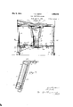
- Figure 1 is a vertical section through a machine embodying my invention, the plane of the section extending from front to rear of the machine, approximately on line l-1 of Fig. 4;
- Fig. 2 is a section on a plane at right angles to the plane of Fig. 1;
- Fig. 3 is a view of the wrapper support with a wrapper thereon, as in Fig. 1, the wrap per in Fig. 3 being for a larger coin than that in Fig. 1;
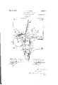
- Fig. 4 is a horizontal section taken approximately on line 44 of Fig. 2;
- Fig. 5 is a section taken on line 55 of Fig. 4;
- Fig. 6 is a view similar to Fig. 5, showing the parts in locking positions and corresponding to a section on line 5 66 of Fig. 7
- Fig. 7 is a view similar to Fig. 4, showing the parts in their locked positions;
- Fig. 8 is a section on line 88 of Fig. 4;
- Fig. 9 is a
- 1 represents what may be termed a table adapted to be supported in a horizontal position by any suitable supports.
- the posts are continued down below the table and are connected at their lower ends by cross pieces 4 carrying on their under sides rubber buttons or feet 5.
- the coins to be sorted are dumped into the tray from which they are fed down upon the table in stack formation.
- an opening 6 large enough to permit the passage of the largest coins to be counted.
- this opening is a comparatively deep trough 7 extending from the front edge of structure rearwardly.
- the bottom wall 8 of the trough inclines downwardly from front to rear end, at a point almost directly below 100 the center of the opening 6, it merges into the wall of a vertical tubular section or sleeve 9 projecting downward from the trough.
- the bore of the tubular portion or sleeve is such that the side thereof that merges with the bottom wall 8 slopes upwardly and forwardly.
- the trough and its tubular section may, therefore, be said to constitute a hopper of peculiar shape, whose outlet is at one side instead of in the center.
- the bore of the lower end of the tubular portion of the hopper is slightly greater in diameter than the largest coin that is to be handled, and this part of the hopper, or an element cooperating therewith to preserve a bore of this size, extends down to a point near the table.
- an open-ended tube or shell 11 which rests at its lower end on the table, but which may he raised by sliding it up into the hopper.
- the member 11 is preferably so constructed or of such a material that the interior is exposed to view, so as to permit the user to note the presence of a bent or damaged coin or any abnormal condition that may arise within this tube during the use of the machine.
- the tube is made of sheet metal filled with many large holes 12. With this construction, the user can see what is going on within the tube and, if a condition is created that requires correction, he need only push the tube up into the hopper to gain access to the coins in the tube.
- the means for ejecting the COlIlS one at a time and pushing them forward consists of a horizontal lever 16 lying on the table and pivoted thereto between its ends, as indicated at 17.
- One end of the lever extends behind the tube and the other endextends to a point near one side of the table.
- On the outer end of the lever is a finger piece 18, and on the inner end is a tongue 19 extending forwardly from the lever into proximity to the rear side of the tube.
- a spring 20 normally holds the lever retracted against a suitable stop 21.
- a ratchet wheel 25 mounted on the table, beside and a short distance away from the guide 15.
- the ratchet wheel is adapted to be turned, step by step, by a pawl 26 pivoted at one end to the rear end of a lever 27 lying between the ratchet wheel and the guides in approximate parallelism with the guides.
- the lever swings on the pivot in or fulcrum 28 between its ends.
- the orward end of the lever is bent laterally opposite and opening in the guide 15; which opening may conveniently be produced by cutting away an entire section of this guide between the ends thereof.
- the ratchet wheel is held against turning backward by a suit able holding pawl 29 pivoted to the table.
- a single spring may conveniently be employed to hold both pawls to the ratchet wheel and to hold the actuating lever 27 at one end of its stroke.
- Such a spring is shown at 30, being connected at one end to the pawl 26 and at the other end to the pawl 29.
- the pawl 29 can swing toward the ratchet wheel only to the point where it engages a fixed stop 31, after which it serves as a stationary anchor for one end of the spring which, being under tension, draws down the pawl 26 and draws over the actuating lever 27.
- each coin engages with the end 32 of the actuating lever for the ratchet wheel, swinging the lever in a direction to turn the ratchet wheel through one step.
- the spring 30 returns the actuating lever and its pawl into their normal positions, ready to be operated again through a working stroke by the next coin that comes along.
- the ratchet wheel will be turned step by step, one step for each coin, as the coins travel along the table and serves as a counter for the coins.
- the indication of the number of coins that have been counted or the indication that a certain predetermined number of coins have been counted may, of course, be given in various ways.
- the user need simply dump the coins in the tray, sweep them with one hand down into the hopper and, with the other hand, operate the ejecting lever until he finds that the lever has become locked, in order to know that he has counted a predetermined number of coins. Then, upon tripping the lock, the user proceeds as before, until the ejecting lever again becomes locked.
- the rock shaft has thereon, toward one end thereof, a projecting pin or finger 36 which, in one angular position of the rock shaft, is adapted to pass up through a hole 37 in the table, just behind the ejecting lever when the ejecting lever is at the end of its working stroke, Toward the other end of the rock shaft, and on the same side thereof as the pin or finger 36, is second pin or finger 33 which is adapted to extend up through a suitable opening in the table and also into an opening or window 39 in the ratchet wheel.
- a tension spring 40, b st shown in l 2 extends between a stationary anchor ll on the under side of the table a radial arm 42 on the rock shaft and constantly exerts a pull tending to turn the rock shaft in a direction to carry the fingers 36 and upward.
- the finger 36 is prevented from assuming its locking position by reason of the fact that the finger 38 bears against the under face of the ratchet wheel, as shown in Fig. 5.
- the finger 36 is held in its idle position, illustrated in Fig. 8.
- the opening or window 39 in. the ratchet wheel registers with the'pin or finger 33, as shown in '4", then there is nothing to prevent the rock shaft from being turned by its spring; the pin or finger 33 rising freely through the opening 39, indicated in Fig. 6, and
- the ejecting lever will be the end of its working stroke at the time that the hole in the ratchet wheel comes into registration with the pin or finger 33. Therefore, whenever the ratchet wheel makes a complete turn, the ejecting lover is locked against return movement and no further coins can be ejected until the ejector is released.
- the ejecting lever may conveniently be unlatched or unlocked by providing the rock shaft with a linger piece by means of which it may be turnel and held in its release position until at least one coin has been ejected, so as to carry the hole or window in the ratchet wheel.
- the finger or arm 42 to which one of the spring ;0 is attached, is shaped so that it at all times extends up through an elongated slot 423 in the table at a point behind the rock shaft, namely, on the opposite side of the rock shaft from that on which the fingers 35' operator need only lace the upwardly proje ting '22 and draw it forward mg -hc rock shaf in its release fore letti r o of this arm,
- the construction which I have just described may easily be adapted to handle more than one size of coin.
- the tube in which the stack of coins is produced need only be large enough to receive nickels, and the guides 14 and 1-5 be far enough apart to permit nickels, such as indicated at B in Fig. 7, to pass between them.
- the free end of the ratchet wheel actuating lever will be moved laterally by a passing nickel through a greater distance than by a penny.
- I employ a long leaf spring 47 which engages with one side of the fulcrum 28 and with the opposite side of each of two pins 48 and 49 located toward the ends of the lever.
- the parts are so proportioned that the spring is bent, in placing it in position, so that it exerts a constant pressure to draw the lever against its primary fulcrum; this pressure being sufficient to kee the lever in contact with the fulcrum whi e the ratchet wheel is being turned.
- ratchet wheel 25 is employed, but, when it is desired to count nickels, the wheel 25 is removed and the wheel 50 is substituted therefor. Any suitable detachable mounting for the ratchet wheel may be utilized. In the arrangement shown, as will best be seen from Fig.
- the combined axle and holding means for the ratchet wheel is a screw 51 having a cylindrical shank 52 whose length equals the combined' thicknesses of the ratchet wheel and table; beyond which shank is a screwthreaded stem 53 on which is a thumb nut 54.
- the ratchet wheel is held in place with capacity to turn freely, whereas, u on unscrewin the nut, the wheel may be li d oil the table and be replaced by the other wheel which may then be secured by the same screw and nut.
- he wrapper-supporting means may comprise a simple long rod 55 having its lowerend bent laterally and then forwardly to support a frusto-conical plug 56, the small end of which is directed upwardly.
- the upper end of the rod may be bent in the opposite direction from the lower end, as indicated at 57, to rovide a finger or stem to extend rearwardly under and engage with the table of the machine.
- the two arm of the bracket are bent upwardly and then rearwardly, as indicated at 59; the extreme rear ends of the arms being bent down, as indicated at 60.
- the table has in the top, near the front edge, and at opposite sides of the path of travel of the coins thereon, two holes 61 into which the down turned sections 60 of the Wrapper holder extend. It will be seen that, when the bracket arms of the wrapper holder are hooked into the top of the table, while the arm 57 engages with the under side of the table, the holder will be firmly supported from the table, with the rod standing at an angle which is determined by the angle at which the arm 57 leaves the same.
- the closed portion of the U-shaped bracket is notched on the inner sides of its two arms, as indicated at 62.
- the operator simply takes hold of the lower end of the wrapper be tween a thumb and forefinger, lifting the wrapper and its contents and at the same time collapsing the lower end of the wrapper between his fingers. After this has been done, the wrapper and its contents may be drawn down out of the bracket at the top and, after the upper end of the wrapper has been collapsed and the coins shifted, if necessary, lengthwise of the wrapper the ends are simply closed in the usual way and the roll is complete.
- Figs. 1 and 7 I have shown a wrapper adapted to receive pennies whereas in Fig. 3 the wrapper is larger, being designed to package nickels. It will be seen that this larger wrapper D is supported in the same way by the holder as the smaller wrapper, excepting, only, that its lower end extends a little farther down over the frusto-conical P lfi fhile I have illustrated and described with particularity only a single preferred form of my invention, I do not desire to be limited tothe exact structural details thus illustrated and described; but intend to cover all forms and arrangements which come within the definitions of my invention constituting the appended claims.
- a support for a stack of coins means to feed the coins one at a time from the bottom of the stack, a counter mounted on the support, operating mechanism for the counter having a. movable element projecting into the path of coins fed from the stack to cause the counter to be actuated by the coins, and means controlled by the counter to engage the feeding means and lock it whenever a predetermined number of coins have been fed from the stack.
- a support means including a finger piece to feed coins across said support along a single definite path, a ratchet wheel on the support, operating means for the ratchet wheel including a lever and a spring tending constantly to hold said lever in a position in which a portion of the lever projects into said. path, and means controlled by said ratchet wheel to engage said finger piece and lock it against feeding movements.
- a support means including a finger piece to feed coins across said support along a single definite path, a ratchet wheel on said support, said ratchet wheel having a hole therein, operating means for said ratchet wheel including an element extending into said path to be actuated by the coins moving along the path, a stop for the finger piece, means tending constantly to move the stop into operative posit-ion with respect to the finger piece, and an element fixed to said step and riding on a face of the ratchet wheel to hold the stop in its idle position, said element registering with the hole in the ratchet wheel in one position of the latter and being of a size to pass through the hole.
- a support for coins means to feed coins across said support along a single definite path, a detachable ratchet wheel on said support, operating means for the ratchet wheel including a pawl and an element projecting into said path to cause the moving coins to turn the ratchet wheel step by step, said operating means having therein a yieldable part to permit said element to continue its movement during a driving stroke after said pawl has come to rest at the end of its driving stroke, whereby the ratchet wheel will be moved step by step as the coins are fed regardless of the number of its teeth within predetermined limits.
- a support for coins means to feed coins across said support along a single definite path, a counter, and operating mechanism for the counter actuated by the coins traveling along said path, said operating mechanism including a counter driving element having a predetermined stroke and an element driven by the passing coins to actuate the driving element, means to permit the element that is driven by the coins to travel during a working stroke through a distance greater than that required to operate the counter to enable it to continue its working stroke after the counter driving element has completed its stroke, whereby coins of different sizes may be accurately counted.
- a support a ratchet wheel on the support; operating mechanism for the ratchet wheel including a pawl having a definite stroke, a lever and a spring to hold the lever at one end of its stroke; means to feed coins across said support along a path intercepting the lever whereby each coin will swing the lever to the other end of its stroke as it passes the lever, means controlled by the ratchet wheel to lock the feeding means for the coins whenever the ratchet wheel makes a complete turn; and means to permit the lever to continue its movement after the pawl has completed a driving stroke to permit the stroke of the lever to increase with the size of the coins without increasing the stroke of the pawl.
- a support for coins means to feed coins across said support along a single definite path, a detachable ratchet wheel on said support, operating means for the ratchet wheel including a pawl and a lever projecting at one end into said path to cause the moving coins to turn the ratchet wheel step by step, a stop to engage the lever at the end of its working stroke, and means to permit said end of the lever to continue its movement after the lever engages said stop, whereby the ratchet wheel will be moved step by step as the coins are fed regardless of the number of its teeth within predetermined limits.
- a table a tray at a considerable distance above and supported by the table, said tray having an opening in the bottom, a narrow open top chute mounted under the tray beneath said opening and having its bottom wall spaced a considerable distance from the opening and inclined downwardly from one side of the opening toward the opposite side, said chute terminating at its lower end in an upright tube, at least the lower portion of the tube being perforated to expose to view coins dropped into the tube, there being between the lower end of the tube and the table a space to permit a single coin to move from the top forward along the table.
- a support a stationary guide projecting above said support, means to feed coins lying flat on the support across the support in edge contact with said guide, a flat lying ratchet wheel mounted on the support, a lever mounted on the support between the ratchet wheel and the guide for swinging movements from and toward the ratchet wheel, a part of the lever extending into the path of coins moving along the guide for engagement with the edges of passing coins, a pawl associated with the lever to operate the ratchet wheel, and spring means tending constantly to hold the lever and the pawl in positions to begin working strokes.
- a support means including a coin-engaging element to feed coins across said support in a single definite path, a counting mechanism, operating means for the counting mechanism including a lever and a spring tending constantly to hold said lever in a position in which a portion of the lever rojects into said path, and means contro led by said counting mechanism to engage said coin-en,- gaging element and hold it against feeding movements.
- a support for coins means to feed coins across said support along a single definite path, two dotachable ratchet wheels adapted to be interchangeably mounted on said sup ort, and operating means for that ratchet w eel that is mounted on the sup ort, said o erating means including a paw adapted to engage with the ratchet wheel and a lever projecting at one end into said ath to cause the moving coins to operate t e lever, together with means to cause the strokes of the pawl end of the lever to be varied according to the number of teeth in the ratchet wheel which is being driven.
Landscapes
- Physics & Mathematics (AREA)
- General Physics & Mathematics (AREA)
- Basic Packing Technique (AREA)
Description
Y 9, 1933- P. c. SMITH 1,908,565
COIN COUNTING MACHINE Filed July 31, 1931 4 Sheets-Sheet l May 9, 1933. Q s n- I 1,908,565
COIN COUNTING MACHINE Filed July 31, 1931 4 Sheets-Sheet 2 May 9, 1933.
P. C. SMITH COIN COUNTING MACHINE Filed July 31, 1931 4 Sheets-Sheet 3 May 1933' SMITH 1,908,565
COIN COUNTING MACHINE Filed July 31, 1931 4 Sheets-Sheet 4 Patented May 9, 1933 PATENT OFFICE PERCY C. SMITH, OF CHICAGO, ILLINOIS COIN COUNTING MACHINE Application filed July 31, 1931. Serial No. 554,299.
The present invention relates to machines for counting coins, particularly coins of small denomination, as, for example, pennies and nickels.
The principal object of the present invention is to produce a machine of this kind which shall be convenient and easy to operate, be accurate and reliable, and yet be inexpensive so as to be available to many who cannot afford to buy the comparatively expensive machines now on the market.
In order that a machine of this kind shall serve its purpose to save time in counting coins, it is necessary that the machine shall operate on coins delivered to it in a haphazard mass. Viewed in one of its aspects, the present invention may be said to have for its object to produce a simple and novel construction that will permit a loose mass of coins to be fed, without requiring the operator to do more than scrape the coins toward a given point.
After a predetermined number of coins W have been counted, it is necessary to enclose them in a wrapper. Viewed in one of its aspects, the present invention may be said to have for its object to produce a simple and novel machine in which the coins are q counted directly into a wrapper, so as to require no further handhng.
So far as I am aware, there are no machines that will count coins of more than one denomination, and, therefore, if it is M necessary to count and package large numbers of pennies, and also nickels, for example, two counting machines are required. Viewed in one of its aspects, the present invention may be said to have for its object to produce a simple and novel machine with which the user, upon making a simple change or substitution, is able to count coins of different sizes and denominations.
The various features of novelty whereby r my invention is characterized will hereina after be pointed out with particularity in the claims; but, for a full understanding of my invention and of its objects and EMIVQLIL tages, reference may be had to the following K0 detailed description taken in connection With the accompanying drawlngs, wherein:
Figure 1 is a vertical section through a machine embodying my invention, the plane of the section extending from front to rear of the machine, approximately on line l-1 of Fig. 4; Fig. 2 is a section on a plane at right angles to the plane of Fig. 1; Fig. 3 is a view of the wrapper support with a wrapper thereon, as in Fig. 1, the wrap per in Fig. 3 being for a larger coin than that in Fig. 1; Fig. 4 is a horizontal section taken approximately on line 44 of Fig. 2; Fig. 5 is a section taken on line 55 of Fig. 4; Fig. 6 is a view similar to Fig. 5, showing the parts in locking positions and corresponding to a section on line 5 66 of Fig. 7 Fig. 7 is a view similar to Fig. 4, showing the parts in their locked positions; Fig. 8 is a section on line 88 of Fig. 4; and Fig. 9 is a section on line 9-9 of Fig. 7
Referring to the drawings, 1 represents what may be termed a table adapted to be supported in a horizontal position by any suitable supports. In the arrangement shown, there are four posts 2, 2 rising from the four corners of the table and supporting at their upper ends a comparatively deep tray 3 of the same transverse dimensions as the table. Since some of the mechanism of the machine is arranged underneath the table, the table must be held above the surface on which the machine rests. In the arrangement shown, the posts are continued down below the table and are connected at their lower ends by cross pieces 4 carrying on their under sides rubber buttons or feet 5.
The coins to be sorted are dumped into the tray from which they are fed down upon the table in stack formation. In the bottom Wall of the tray, near the front and about midway between the sides of the tray, is an opening 6 large enough to permit the passage of the largest coins to be counted. Under- 95 neath this opening is a comparatively deep trough 7 extending from the front edge of structure rearwardly. The bottom wall 8 of the trough inclines downwardly from front to rear end, at a point almost directly below 100 the center of the opening 6, it merges into the wall of a vertical tubular section or sleeve 9 projecting downward from the trough. The bore of the tubular portion or sleeve is such that the side thereof that merges with the bottom wall 8 slopes upwardly and forwardly. The trough and its tubular section may, therefore, be said to constitute a hopper of peculiar shape, whose outlet is at one side instead of in the center.
The bore of the lower end of the tubular portion of the hopper is slightly greater in diameter than the largest coin that is to be handled, and this part of the hopper, or an element cooperating therewith to preserve a bore of this size, extends down to a point near the table. In the arrangement shown, there is slidable within the tubular part 9 an open-ended tube or shell 11 which rests at its lower end on the table, but which may he raised by sliding it up into the hopper. The member 11 is preferably so constructed or of such a material that the interior is exposed to view, so as to permit the user to note the presence of a bent or damaged coin or any abnormal condition that may arise within this tube during the use of the machine. In the arrangement shown, the tube is made of sheet metal filled with many large holes 12. With this construction, the user can see what is going on within the tube and, if a condition is created that requires correction, he need only push the tube up into the hopper to gain access to the coins in the tube.
As the coins are swept along the bottom of the tray and into the hole 6, they drop down upon the inclined wall 8 and slide into the upper end of the tube, finally coming to rest on the table; one coin piling upon the preceding coin until a stack is produced, as indicated in Fig. 1; the coins being indicated at A. This settling of the coins, flat upon each other in stack formation, regardless of the positions which they have as they pass down through the o ning in the table, is made possible throug offsetting the hopper outlet and the opening in the table; thus compelling the coins as they drop down from the table to fall on the inclined bottom of the hopper, lay themselves flat thereon, and then slide edgewise into the tubular receptacle. As will hereinafter .be explained, the
'coins are fed, one at a time, from the bottom of the stack, forwardly along the table. Therefore, there must be a passage at the bottom of the tube, just above the table, to permit egress of a single coin. This can conveniently be accomplished by cutting away the lower end of the tube at the front and at the rear for a height or depth slightly greater than the thickest coin to be handled. The lower end portions of the tube are provided with downwardly projecting lugs or cars 13, as best shown in Fig. 2, that enter little holes in the table. In this way I am able to support the tube in such an manner that it will not become displaced angularly of its long axis.
On top of the table, in front of the tube, are two parallel ribs or guides 14 and 15 tangent to opposite sides of the tube and extending from the tube into proximity with the forward edge of the table. When a coin is pushed forward out of the bottom of the tube, it enters between the guides 14 and 15 and must, therefore, follow a definite path from the tube to a discharge point at the front edge of the table.
In the arr ement shown, the means for ejecting the COlIlS one at a time and pushing them forward consists of a horizontal lever 16 lying on the table and pivoted thereto between its ends, as indicated at 17. One end of the lever extends behind the tube and the other endextends to a point near one side of the table. On the outer end of the lever is a finger piece 18, and on the inner end is a tongue 19 extending forwardly from the lever into proximity to the rear side of the tube. A spring 20 normally holds the lever retracted against a suitable stop 21. When the finger piece is pressed back, as viewed in Fig. 4, the tongue 19 moves forward along the table and against the rear edge of the lowermost coin in the stack. There is a second stop 22 for the lever, arranged in front of the same. \Vhen the finger piece has been pressed back far enough to bring the lever up against the stop 22, as indicated at Fig. 7, the tongue will have passed diametrically across the lower end of the tube and will have pushed the lowermost coin completely out of the tube and into the space between the guides. Upon release of t e finger piece, the spring retracts the lever, allowing the stack of coins to drop until the lowermost coin rests on the table, whereupon the cycle just described may be repeated. It will be seen that the second coin ejected pushes the first coin ahead of it along the table, whereas the third coin pushes the second coin. Therefore, if coins are delivered into the hopper at least as fast as they are fed forward by means of the ejecting lever, a regular flow of coins to the forward edge of the table may be maintained.
As the coins pass forward between the guides they are counted. In the arrangement shown, there is provided for this purpose a ratchet wheel 25 mounted on the table, beside and a short distance away from the guide 15. The ratchet wheel is adapted to be turned, step by step, by a pawl 26 pivoted at one end to the rear end of a lever 27 lying between the ratchet wheel and the guides in approximate parallelism with the guides. The lever swings on the pivot in or fulcrum 28 between its ends. The orward end of the lever is bent laterally opposite and opening in the guide 15; which opening may conveniently be produced by cutting away an entire section of this guide between the ends thereof. The ratchet wheel is held against turning backward by a suit able holding pawl 29 pivoted to the table. A single spring may conveniently be employed to hold both pawls to the ratchet wheel and to hold the actuating lever 27 at one end of its stroke. Such a spring is shown at 30, being connected at one end to the pawl 26 and at the other end to the pawl 29. The pawl 29 can swing toward the ratchet wheel only to the point where it engages a fixed stop 31, after which it serves as a stationary anchor for one end of the spring which, being under tension, draws down the pawl 26 and draws over the actuating lever 27. The parts are so proportioned that normally the laterally bent front end 32 of the lever 27 projects into the space between the guides 14 and 15, namely, into the path of the coins. Then, upon operating the ejecting lever to push the coins ahead, each coin engages with the end 32 of the actuating lever for the ratchet wheel, swinging the lever in a direction to turn the ratchet wheel through one step. As soon as a coin has passed, the spring 30 returns the actuating lever and its pawl into their normal positions, ready to be operated again through a working stroke by the next coin that comes along.
Consequently, the ratchet wheel will be turned step by step, one step for each coin, as the coins travel along the table and serves as a counter for the coins. The indication of the number of coins that have been counted or the indication that a certain predetermined number of coins have been counted may, of course, be given in various ways. For the sake of simplicity, I prefer to have the ratchet wheel act to stop the ejecting of the coins whenever a predetermined number have been ejected. By this means, the user need simply dump the coins in the tray, sweep them with one hand down into the hopper and, with the other hand, operate the ejecting lever until he finds that the lever has become locked, in order to know that he has counted a predetermined number of coins. Then, upon tripping the lock, the user proceeds as before, until the ejecting lever again becomes locked.
ASSUHIlH that pennies a 'e to be counted, the parts should be so proportioned as to stop the machine whenever fifty pennies have been ejected, since pennies are ordinarily packaged in rolls each containing fifty penniesx' I have, therefore, provided the ratchet wh el 25 with fifty teeth, so that it must make a complete turn in order to count fifty pennies. Whenever the ratchet wheel reaches what may be termed its zero position, it causes the ejecting lever to locked. This may conveniently be accomplished as follows: Rotatably supported beneath the table, in suitable brackets 33 and 34, is a long rock shaft 35. The rock shaft has thereon, toward one end thereof, a projecting pin or finger 36 which, in one angular position of the rock shaft, is adapted to pass up through a hole 37 in the table, just behind the ejecting lever when the ejecting lever is at the end of its working stroke, Toward the other end of the rock shaft, and on the same side thereof as the pin or finger 36, is second pin or finger 33 which is adapted to extend up through a suitable opening in the table and also into an opening or window 39 in the ratchet wheel. A tension spring 40, b st shown in l 2, extends between a stationary anchor ll on the under side of the table a radial arm 42 on the rock shaft and constantly exerts a pull tending to turn the rock shaft in a direction to carry the fingers 36 and upward. Normally, however, the finger 36 is prevented from assuming its locking position by reason of the fact that the finger 38 bears against the under face of the ratchet wheel, as shown in Fig. 5. At this time the finger 36 is held in its idle position, illustrated in Fig. 8. However, when the opening or window 39 in. the ratchet wheel registers with the'pin or finger 33, as shown in '4", then there is nothing to prevent the rock shaft from being turned by its spring; the pin or finger 33 rising freely through the opening 39, indicated in Fig. 6, and
the finger 36 passing up through the window 37 in the table and projecting into the path of movement of the ejecting lever, as indicated in Fig. 9. The ejecting lever will be the end of its working stroke at the time that the hole in the ratchet wheel comes into registration with the pin or finger 33. Therefore, whenever the ratchet wheel makes a complete turn, the ejecting lover is locked against return movement and no further coins can be ejected until the ejector is released. The ejecting lever may conveniently be unlatched or unlocked by providing the rock shaft with a linger piece by means of which it may be turnel and held in its release position until at least one coin has been ejected, so as to carry the hole or window in the ratchet wheel. away from the pin or finger 33. in the arrangement shown, the finger or arm 42, to which one of the spring ;0 is attached, is shaped so that it at all times extends up through an elongated slot 423 in the table at a point behind the rock shaft, namely, on the opposite side of the rock shaft from that on which the fingers 35' operator need only lace the upwardly proje ting '22 and draw it forward mg -hc rock shaf in its release fore letti r o of this arm,
through a working stroke, in order to leave the machine in a condition to make a complete count of fifty pennies without requiring further attention of the operator than the working of the ejector and the sweeping or scraping of the pennies into the hopper.
I have found that the construction which I have just described may easily be adapted to handle more than one size of coin. In order that nickels, for example, may be handled and counted with the same facility as pennies, the tube in which the stack of coins is produced need only be large enough to receive nickels, and the guides 14 and 1-5 be far enough apart to permit nickels, such as indicated at B in Fig. 7, to pass between them. Of course, since the nickels are larger in diameter than pennies, the free end of the ratchet wheel actuating lever will be moved laterally by a passing nickel through a greater distance than by a penny. I compensate for this difference in the extent of movement of the free end of the lever by causing the pawl end of the actuating lever to be brought to rest at the end of each working stroke through engagement with a stationary stop 45, and permitting the free end of the lever to continue its movement after the pawl has come to rest. In the arrangement shown, the yielding of the actuating lever is accomplished by having the stationary pivot pin or fulcrum 28 seated in a notch 46 opening out of that edge of the lever which is on the side toward the guides. Therefore, after the pawl end of the lever has engaged with the stationary stop 45, the lever may swing vabout this stop as a fulcrum, drawing away from its primary fulcrum. However, means must be provided to hold the lever against its primary fulcrum while the ratchet wheel is being turned. Therefore, as best shown in Fig. 4, I employ a long leaf spring 47 which engages with one side of the fulcrum 28 and with the opposite side of each of two pins 48 and 49 located toward the ends of the lever. The parts are so proportioned that the spring is bent, in placing it in position, so that it exerts a constant pressure to draw the lever against its primary fulcrum; this pressure being sufficient to kee the lever in contact with the fulcrum whi e the ratchet wheel is being turned.
Ordinarily, nickels are packaged in rolls each containing forty nickels so that, if nickels are being counted by the machine, as heretofore described, they will not he automatically separated into lots of forty. I, therefore, provide an additional ratchet wheel, as shown at 50 in Fig. 7, this wheel having forty teeth. This wheel also has the opening or window 39. When pennies are to be counted, the ratchet wheel 25 is employed, but, when it is desired to count nickels, the wheel 25 is removed and the wheel 50 is substituted therefor. Any suitable detachable mounting for the ratchet wheel may be utilized. In the arrangement shown, as will best be seen from Fig. 2, the combined axle and holding means for the ratchet wheel is a screw 51 having a cylindrical shank 52 whose length equals the combined' thicknesses of the ratchet wheel and table; beyond which shank is a screwthreaded stem 53 on which is a thumb nut 54. When the parts are assembled, as shown in Fig. 2, the ratchet wheel is held in place with capacity to turn freely, whereas, u on unscrewin the nut, the wheel may be li d oil the table and be replaced by the other wheel which may then be secured by the same screw and nut.
It will thus be seen that I have produced a simple and novel machine that will count a predetermined number of coins and feed them to the edge of a table or support where they may be collected in any suitable manner. I have also, however, made provision for delivering the coins directly into the usual tubular wrappers in which coins are packaged; thereby avoiding rehandlinfg of the coins after the have been counte have found that, i one of the ordinary tubular wrappers is supported at the front end of the table with its upper end on'iy partiall opened so as to provide an elongated mouth close to and with its long axis parallel to the front edge of the table, the coins will drop into the wrapper from the table. I have also found that, if the wrapper is held in an inclined position, with its lower end somewhat forward of or outward from the upper end, the coins will set themselves in proper roll or stack formation, provided that the lower end of the wrapper has been opened into its cylindrical form. I have, therefore provided means to support in this manner wrappers for such coins as may be counted by my improved machine.
he wrapper-supporting means may comprise a simple long rod 55 having its lowerend bent laterally and then forwardly to support a frusto-conical plug 56, the small end of which is directed upwardly. The upper end of the rod may be bent in the opposite direction from the lower end, as indicated at 57, to rovide a finger or stem to extend rearwardly under and engage with the table of the machine. On the front side of the rod, near the top, is fixed a U-shaped bracket 58, the rod joining the bracket at the middle of the connecting piece between the arms of the bracket. The two arm of the bracket are bent upwardly and then rearwardly, as indicated at 59; the extreme rear ends of the arms being bent down, as indicated at 60. The table has in the top, near the front edge, and at opposite sides of the path of travel of the coins thereon, two holes 61 into which the down turned sections 60 of the Wrapper holder extend. It will be seen that, when the bracket arms of the wrapper holder are hooked into the top of the table, while the arm 57 engages with the under side of the table, the holder will be firmly supported from the table, with the rod standing at an angle which is determined by the angle at which the arm 57 leaves the same. The closed portion of the U-shaped bracket is notched on the inner sides of its two arms, as indicated at 62. When a tubular wrapper, such as indicated at C in Fig. 4, is partially opened and slipped down through the bracket, the edges or corners produced at the creases or folds in the original flattened wrapper, set in the notches 62, prevent the wrapper from falling or being shifted in the forward direction along the bracket. The lower end of the wrapper slips over the frusto-conical plug whose upper face is at right angles to the long axis of the wrapper so that, as coins drop down upon the plug, they will lie fiat thereon at right angles to the long axis of the wrapper. After the proper number of coins have been delivered into a wrap-per, the operator simply takes hold of the lower end of the wrapper be tween a thumb and forefinger, lifting the wrapper and its contents and at the same time collapsing the lower end of the wrapper between his fingers. After this has been done, the wrapper and its contents may be drawn down out of the bracket at the top and, after the upper end of the wrapper has been collapsed and the coins shifted, if necessary, lengthwise of the wrapper the ends are simply closed in the usual way and the roll is complete.
In Figs. 1 and 7 I have shown a wrapper adapted to receive pennies whereas in Fig. 3 the wrapper is larger, being designed to package nickels. It will be seen that this larger wrapper D is supported in the same way by the holder as the smaller wrapper, excepting, only, that its lower end extends a little farther down over the frusto-conical P lfi fhile I have illustrated and described with particularity only a single preferred form of my invention, I do not desire to be limited tothe exact structural details thus illustrated and described; but intend to cover all forms and arrangements which come within the definitions of my invention constituting the appended claims.
I claim:
1. In a coin counting machine, a support for a stack of coins, means to feed the coins one at a time from the bottom of the stack, a counter mounted on the support, operating mechanism for the counter having a. movable element projecting into the path of coins fed from the stack to cause the counter to be actuated by the coins, and means controlled by the counter to engage the feeding means and lock it whenever a predetermined number of coins have been fed from the stack.
2. In a coin counting machine, a support, means including a finger piece to feed coins across said support along a single definite path, a ratchet wheel on the support, operating means for the ratchet wheel including a lever and a spring tending constantly to hold said lever in a position in which a portion of the lever projects into said. path, and means controlled by said ratchet wheel to engage said finger piece and lock it against feeding movements.
8. In a coin counting machine, a support, means including a finger piece to feed coins across said support along a single definite path, a ratchet wheel on said support, said ratchet wheel having a hole therein, operating means for said ratchet wheel including an element extending into said path to be actuated by the coins moving along the path, a stop for the finger piece, means tending constantly to move the stop into operative posit-ion with respect to the finger piece, and an element fixed to said step and riding on a face of the ratchet wheel to hold the stop in its idle position, said element registering with the hole in the ratchet wheel in one position of the latter and being of a size to pass through the hole.
4. In a coin counting machine, a support for coins, means to feed coins across said support along a single definite path, a detachable ratchet wheel on said support, operating means for the ratchet wheel including a pawl and an element projecting into said path to cause the moving coins to turn the ratchet wheel step by step, said operating means having therein a yieldable part to permit said element to continue its movement during a driving stroke after said pawl has come to rest at the end of its driving stroke, whereby the ratchet wheel will be moved step by step as the coins are fed regardless of the number of its teeth within predetermined limits.
5. In a coin counting machine, a support for coins, means to feed coins across said support along a single definite path, a counter, and operating mechanism for the counter actuated by the coins traveling along said path, said operating mechanism including a counter driving element having a predetermined stroke and an element driven by the passing coins to actuate the driving element, means to permit the element that is driven by the coins to travel during a working stroke through a distance greater than that required to operate the counter to enable it to continue its working stroke after the counter driving element has completed its stroke, whereby coins of different sizes may be accurately counted.
6. In a coin counting machine, a support, a ratchet wheel on the support; operating mechanism for the ratchet wheel including a pawl having a definite stroke, a lever and a spring to hold the lever at one end of its stroke; means to feed coins across said support along a path intercepting the lever whereby each coin will swing the lever to the other end of its stroke as it passes the lever, means controlled by the ratchet wheel to lock the feeding means for the coins whenever the ratchet wheel makes a complete turn; and means to permit the lever to continue its movement after the pawl has completed a driving stroke to permit the stroke of the lever to increase with the size of the coins without increasing the stroke of the pawl.
7. In a coin counting machine, a support for coins, means to feed coins across said support along a single definite path, a detachable ratchet wheel on said support, operating means for the ratchet wheel including a pawl and a lever projecting at one end into said path to cause the moving coins to turn the ratchet wheel step by step, a stop to engage the lever at the end of its working stroke, and means to permit said end of the lever to continue its movement after the lever engages said stop, whereby the ratchet wheel will be moved step by step as the coins are fed regardless of the number of its teeth within predetermined limits.
8. In a coin counting machine, a table, a tray at a considerable distance above and supported by the table, said tray having an opening in the bottom, a narrow open top chute mounted under the tray beneath said opening and having its bottom wall spaced a considerable distance from the opening and inclined downwardly from one side of the opening toward the opposite side, said chute terminating at its lower end in an upright tube, at least the lower portion of the tube being perforated to expose to view coins dropped into the tube, there being between the lower end of the tube and the table a space to permit a single coin to move from the top forward along the table.
9. In a coin counting machine, a support, a stationary guide projecting above said support, means to feed coins lying flat on the support across the support in edge contact with said guide, a flat lying ratchet wheel mounted on the support, a lever mounted on the support between the ratchet wheel and the guide for swinging movements from and toward the ratchet wheel, a part of the lever extending into the path of coins moving along the guide for engagement with the edges of passing coins, a pawl associated with the lever to operate the ratchet wheel, and spring means tending constantly to hold the lever and the pawl in positions to begin working strokes.
10. In a coin counting machine, a support, means including a coin-engaging element to feed coins across said support in a single definite path, a counting mechanism, operating means for the counting mechanism including a lever and a spring tending constantly to hold said lever in a position in which a portion of the lever rojects into said path, and means contro led by said counting mechanism to engage said coin-en,- gaging element and hold it against feeding movements.
11. In a coin counting machine, a support for coins, means to feed coins across said support along a single definite path, two dotachable ratchet wheels adapted to be interchangeably mounted on said sup ort, and operating means for that ratchet w eel that is mounted on the sup ort, said o erating means including a paw adapted to engage with the ratchet wheel and a lever projecting at one end into said ath to cause the moving coins to operate t e lever, together with means to cause the strokes of the pawl end of the lever to be varied according to the number of teeth in the ratchet wheel which is being driven.
In testimony whereof, I sign this specification.
PERCY C. SMITH.
Priority Applications (1)
| Application Number | Priority Date | Filing Date | Title |
|---|---|---|---|
| US554299A US1908565A (en) | 1931-07-31 | 1931-07-31 | Coin counting machine |
Applications Claiming Priority (1)
| Application Number | Priority Date | Filing Date | Title |
|---|---|---|---|
| US554299A US1908565A (en) | 1931-07-31 | 1931-07-31 | Coin counting machine |
Publications (1)
| Publication Number | Publication Date |
|---|---|
| US1908565A true US1908565A (en) | 1933-05-09 |
Family
ID=24212831
Family Applications (1)
| Application Number | Title | Priority Date | Filing Date |
|---|---|---|---|
| US554299A Expired - Lifetime US1908565A (en) | 1931-07-31 | 1931-07-31 | Coin counting machine |
Country Status (1)
| Country | Link |
|---|---|
| US (1) | US1908565A (en) |
Cited By (3)
| Publication number | Priority date | Publication date | Assignee | Title |
|---|---|---|---|---|
| US2750106A (en) * | 1956-06-12 | Fare collection apparatus | ||
| US6626752B2 (en) * | 2000-06-07 | 2003-09-30 | F. Zimmermann Gmbh & Co. Kg | Device for sorting coins with a coin collection container configured as a sleeve container |
| US6733380B1 (en) * | 2000-09-01 | 2004-05-11 | De La Rue Cash Systems, Inc. | Coin wrapping attachments for a coin sorter |
-
1931
- 1931-07-31 US US554299A patent/US1908565A/en not_active Expired - Lifetime
Cited By (3)
| Publication number | Priority date | Publication date | Assignee | Title |
|---|---|---|---|---|
| US2750106A (en) * | 1956-06-12 | Fare collection apparatus | ||
| US6626752B2 (en) * | 2000-06-07 | 2003-09-30 | F. Zimmermann Gmbh & Co. Kg | Device for sorting coins with a coin collection container configured as a sleeve container |
| US6733380B1 (en) * | 2000-09-01 | 2004-05-11 | De La Rue Cash Systems, Inc. | Coin wrapping attachments for a coin sorter |
Similar Documents
| Publication | Publication Date | Title |
|---|---|---|
| US2103367A (en) | Dispensing machine | |
| US1908565A (en) | Coin counting machine | |
| US1926848A (en) | Vending machine | |
| US1948107A (en) | Multiple coin actuated vending machine | |
| US2231952A (en) | Coin vending machine | |
| US2320378A (en) | Vending machine | |
| US1814795A (en) | Vending machine | |
| US2310072A (en) | Vending machine | |
| US2504990A (en) | Newspaper vending machine | |
| US532526A (en) | John annan bryce | |
| US748934A (en) | Machine for operating upon coins | |
| US998830A (en) | N-handling machine. | |
| US1745254A (en) | Vending machine | |
| US1507999A (en) | Vending machine | |
| US976089A (en) | Vending-machine. | |
| US1978187A (en) | Coin counting and collecting means | |
| US402374A (en) | Vending apparatus | |
| US2708053A (en) | Apparatus for vending articles | |
| US2816689A (en) | Merchandise vending mechanism | |
| US869635A (en) | Cigar-vending machine. | |
| US1159298A (en) | Vending-machine. | |
| US1385359A (en) | Selective change-maker | |
| US802551A (en) | Coin counting, registering, and bagging machine. | |
| US1861212A (en) | Vending machine | |
| US1280417A (en) | Vending-machine. |