US1908475A - Reversing apparatus for hat making machinery and the like - Google Patents
Reversing apparatus for hat making machinery and the like Download PDFInfo
- Publication number
- US1908475A US1908475A US136031A US13603126A US1908475A US 1908475 A US1908475 A US 1908475A US 136031 A US136031 A US 136031A US 13603126 A US13603126 A US 13603126A US 1908475 A US1908475 A US 1908475A
- Authority
- US
- United States
- Prior art keywords
- shaft
- hat
- driving
- rotation
- hat block
- Prior art date
- Legal status (The legal status is an assumption and is not a legal conclusion. Google has not performed a legal analysis and makes no representation as to the accuracy of the status listed.)
- Expired - Lifetime
Links
- 230000007935 neutral effect Effects 0.000 description 10
- 229910052751 metal Inorganic materials 0.000 description 8
- 239000002184 metal Substances 0.000 description 8
- 230000006835 compression Effects 0.000 description 6
- 238000007906 compression Methods 0.000 description 6
- 238000010276 construction Methods 0.000 description 4
- 230000000994 depressogenic effect Effects 0.000 description 4
- 230000000694 effects Effects 0.000 description 3
- 238000005461 lubrication Methods 0.000 description 3
- 229910052782 aluminium Inorganic materials 0.000 description 2
- XAGFODPZIPBFFR-UHFFFAOYSA-N aluminium Chemical compound [Al] XAGFODPZIPBFFR-UHFFFAOYSA-N 0.000 description 2
- 230000001680 brushing effect Effects 0.000 description 2
- 230000000881 depressing effect Effects 0.000 description 2
- 238000012856 packing Methods 0.000 description 2
- 239000002245 particle Substances 0.000 description 2
- 238000005498 polishing Methods 0.000 description 2
- 239000002023 wood Substances 0.000 description 2
- XMTQQYYKAHVGBJ-UHFFFAOYSA-N 3-(3,4-DICHLOROPHENYL)-1,1-DIMETHYLUREA Chemical compound CN(C)C(=O)NC1=CC=C(Cl)C(Cl)=C1 XMTQQYYKAHVGBJ-UHFFFAOYSA-N 0.000 description 1
- 241001547070 Eriodes Species 0.000 description 1
- 241000809861 Xerocomus bubalinus Species 0.000 description 1
- 238000005452 bending Methods 0.000 description 1
- 239000005293 duran Substances 0.000 description 1
- 239000000835 fiber Substances 0.000 description 1
- 239000002783 friction material Substances 0.000 description 1
- 239000010985 leather Substances 0.000 description 1
- 239000000314 lubricant Substances 0.000 description 1
- 230000001050 lubricating effect Effects 0.000 description 1
- 108010085990 projectin Proteins 0.000 description 1
- 230000035939 shock Effects 0.000 description 1
- 210000003813 thumb Anatomy 0.000 description 1
- 239000002699 waste material Substances 0.000 description 1
Images


Classifications
-
- A—HUMAN NECESSITIES
- A42—HEADWEAR
- A42C—MANUFACTURING OR TRIMMING HEAD COVERINGS, e.g. HATS
- A42C1/00—Manufacturing hats
- A42C1/02—Making hat-bats; Bat-forming machines; Conical bat machines; Bat-forming tools
Definitions
- One: of the objects of the invention is to provide apparatus of the above nature which is practical and thoroughly eliicient.
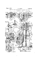
- Figure 1 is a side elevation of the machine with parts cut away to better show portions of the structure
- Figure 2 is a rear elevation of the machine
- Figure 3 is a central vertical section through upper portion of the machine parts in enlarged detail
- Figure 4 is a section showing parts included at the bottom portion of Figure 3, together with additional parts;
- Figure 5 is a section taken along the line 55 of Figure 1;
- Figure 6 is a section showing in enlarged detail an arrangement employed in. connection with certain bearings
- F'gure 8 is a detail view of a foot-operated mechanism which is shown partly in Figure 1; V
- Figure 9 is a sectional view of the body of a machine embodying a modified form of control and automatically acting mechanism for effecting reversals of rotation;
- Figure 10 is a view from the lef -hand side of Figure 9;
- FIG 11 shows in larger detail a cam construction shown in Figures 9 and 10;
- FIG. 12 isa section taken along the line 12-12 of Figure 10 5 Figure 13 shows in larger detail the cam drive shown in Figure 10;
- Figure 14 is asection taken along the line IMP-14E of Figure 13;
- Figure 15 is a-section taken along the line 1515 of FigureS);
- Figure 16 is a sectional view similar to Figure 9 but with the automatic reversing mechanism omitted and showing chiefly parts of the foot control;
- Figurel? isa plan view of Figure 16 showing a double foot lever and broken 'away to show the lever connections;
- Figure 18 isan elevation of the double foot lever
- FIGS 19 and 20 are detail views of parts shown in Figures 17 and 18';
- FigureQl is a detail view of parts of the control
- 7 Figure 22 ' is a plan View of one of the parts shownin Figure 21, with its connecting parts.
- an. upright hollow frame which preferably comprises-two main parts, a lower portion 10 provided with a bottom flange 11 which rests upon'thevfioor, and an upper portion 12 which rests upon'the lower portion or base 10 audis securedthereto as by suitable bolts 13.
- a platform or table 15 Projecting upwardly through the center of the table 15 is the upper end 16a of a shaft 16 which is rotated by mechanism which will be described presently.
- the projectin shaft portion or spindle 16a is adapted to support a hat block 17 over which the hat to be operated upon is stretched.
- the shaft 16 is rapidly rotated, rotating therewith the hat block 17 and the hat supported thereon, while the desired operation of pouncing, brushing or polishing the hat is performed.
- a casing or guard 18 to receive the particles of fur or hair which may be removed from the hat, and this casing is provided with one or more outlets 19 preferably at the rear to which may be attached a suitable suction for carrying away the particles which collect within the casing 18.
- an electric motor 20 which, through a belt 21 is adapted to drive this apparatus as will be described.
- a suitable starting box for the motor is illustrated at 22.
- An idler pulley 23 is provided for adjusting the tension of the driving belt 21.
- This pulley is shown mounted upon a shaft 24 which is supported in the upper end of an arm 25, the arm 25 being pivoted to the frame 10 at its lower end 26.
- the arm 25 may thus be swung toward and away from the frame 10 to adjust the tension of the belt 21 and it is locked in the position to which it is adjusted by a hand screw 27 engaging the slot in a horizontal arm 28.
- this machine may be driven by any other suitable means such, for example, as from an over-head jack shaft or the like, and the motor drive just described is simply illustrative of one possible form of drive.
- FIG. 3 there is shown the shaft 16 which is rotatably supported within the frame or casing portion 12. Adjacent the top of the casing the shaft 16 is supported by a bearing 29 which is preferably a ball bearing. Adjacent its lower end the shaft is supported against radial and axial thrust by a double ball bearing 30. The outer race of this ball bearing 30 is held by a collar 31 in the upper end of a cup-shaped member 32. This member 32 is rigidly secured to the bottom wall 12a of the frame 12 by locking nuts 33 threaded upon the hollow downwardly projecting part 3211 of the.
- a second pulley 38 Adjacent the lower portion of the shaft 16 and also concentric therewith is a second pulley 38 which is also driven by the belt 37 (as will be described) but in a direction opposite to the direction of rotation of the pulley 36, as indicated by the arrows.
- the pulley 36 is mounted upon the sleeve 35 through a double ball bearing 39.
- the pulley 38 is mounted upon the sleeve or cupshaped member 32 by a double ball bearing 40.
- the pulleys 36 and 38 are mounted within the frame 12 for rotation about an axis substantially coincident with that of the shaft 16 and for rotation relative to the shaft 16.
- a member 41 which has an upwardly extending outwardly flaring flange 42 and a similar downwardly extending and outwardly flaring flange 43.
- the inner faces of the flanges 42 and 43 are preferably covered with a suitable friction material 44, which may be leather, and thus the member 41 forms in eflect a double faced cone clutch member.
- the member 41 is keyed to the shaft 16 so that it is in driving connection therewith, but is movable axially of the shaft 16.
- the driving connection may be formed, for example, by a pin 45 passing through an axial slot in the shaft and secured in the hub of the member 41.
- the shaft 16 is hollow and projecting upwardly thereinto is a rod or shaft 46 through which the pin 45 passes also. The rod 46 thus rotates with the shaft 16 and with the member 41.
- the pulley 36 rotated in one direction by the belt 37, has a clutch member associated therewith forengagement with the clutch member 41.
- the pulley 38 driven by the belt 37 in a direction opposite to thatin which the pulley 36 is driven, has
- the clutch member 41 may be moved to an intermediate position in which it engages neither the pulley 36 nor the pulley 38, in which position the rotation of the shaft 16 is interrupted.
- the clutch member 41 is operated to reverse the direction of rotation, as just described, the parts which are reversed comprise simply theclutch member 41, the hollow light shaf 16 with the hat block thereon, and the rod 46.
- the member 41 is preferably made of a light but strong metal such, fer example, as aluminum or airplane metal.
- the shaft 16 and the rod 46 are also preferably made as light as possible. The number and weightof the parts which are reversed in .direc'tionof rotation are thus re depictd to a minimum and the reversal takes place quickly and easily.
- the pulleys 36 and 38 may be made of a heavy construction so that their momentum is considerable, these parts rotating always in the same direction.
- the rod 46 is supported at its lower end in a double ball bearing 49 the outer race of which is held in a cup-shaped-member 50.
- This member 50 is slidably held in a depending guiding part 51 and has swiv'eled to the bottom thereof, by a pin 52, a rod 53.
- a pin 52 a rod 53.
- About the rod 53 (Fig.4) is an adjustable nut 54 and a compression spring 55 ac ing between the nut and the part 51a.
- the spring 55 thus urges the member 50 downwardly and with it the shaft 46 and the clutch member 41.
- the spring 55 thus normally tends to hold the clutch member 41 in driving engagement with the pulley 38.
- the clutch member 41 may be moved upwardly out of engagement with the pulley and, by further movement, into dr ving engagement with the pulley 36.
- the spring55 servesto urge the clutch member 41 into driving engagement with the pulley 38 and that a downward pressurewith the foot upon the pedal 58 will urge the clutch member 41 upwardly intodriving engagement with the pulley 36.
- Adjacent tothe foot pedal 58 is swiveled a second pedal 59 which is in the shape ofa bell crank lever and is urged-to swinginthe direction indicated by the arrow in Figure 8 by a spring 60.
- This spring 60 is shown coiled about a post-61 threaded into the base flange ll of the frame.
- the pivot 'post'62 for the 590 pedal 59 is also secured in this base'fiange 11.
- Themeinber 59 is provided, on its side toward thepedal '58, with a projection-or tooth 63 which is adapted to catch over the edge of a plate 64secured to the under side of the foot pedal 58. In the position of the parts shown in Figure8, the tooth 63 prevents the foot lever 58 from swinging upwardly under the urge of the spring 55 on the rod 53.
- the foot lever-58 and the foot lever 59 are 5505 .so positioned that both may be engaged by the foot of the operator.
- the operator places his foot upon :the pedal 58 in such ,a manner that the toe of his foot depresses the pedal 59, thereby moving the tooth 63 out of engagement with :the plate 64.
- the shaft 16 is rotated in one direction and, bydepressing the pedal 58, the shaft 16 M15 is rotated in the oppositedirection.
- an adjustable stop is preferably provided beneath the foot pedal 58. As shown in Figure 8, this stop takes the form of a post 65 which is threaded into the base flange 11 and may be locked by a nut 66 in 9125 the position to which it is adjusted. 'From the'foregoing, it will be seen that the clutch member '41 is operated with the greatest operator being required simply to exert a light pressure upon the foot pedal 58. WVhen it is desired to stop the operation of the machine, the member 59is permitted to swing forward under the urge of its spring 60 and thereupon the tooth 63 engages with the foot pedal 58, holding the clutch member 41 in neutral position.
- the oil'which is fed into the oil cup 67 and down throughthe passage 68 collects in the space 69 above the plug 70 which thus forms an oil reservoir.
- this oil being thrown about by centrifugal force, tends to rise through the passage 68.
- In the shaft 16 just above the bearing 29 are positioned one or more radial passages 71 communicating with the space 69. The oil is thrown through these radial passages and runs down through the bearing 29.
- Through the sleeve 35 are provided several oil passages 72 through which the oil runs from the bearing 29 to the hearing 39. From the bearing 39 the oil runs downwardly through openings 73 'in the web of the clutch member 41 and into the bearing 30.
- the oil thrown against the inner wall of the depending flange 76 runs down within the part 48 to oil the bearing 40.
- an upstanding flange 77 which catches some of the oil which passes downwardly through the web of the clutch member 41 and guides it to oil the bearing 30.
- the oil leaving the bearing 30 is permitted to 'run down along the shaft 46 within the member 32 to oil the lowest bearing 49.
- each of the several bearings for the rotating parts is dependably lubricated from a single oil reservoir'which is conveniently supplied with oil through the upper end of the spindle 16d.
- a ring 78 Secured to the upper side of the hub of the pulley 36 is a ring 78 which carries packing 79 to prevent the oil from flying upwardly out of the bearing 39 and thus gaining access to theibelt 37.
- a similarring 80 provided with packing 81, is provided on the lower end of the hub of the pulley 38. Oil which may accumulate in the bottom of the casing 12 may be drawn out through a passage closed by a plug 82.
- Suitable supporting members 87 are provided to brace and strengthen the mounting of the supporting bracket 85.
- the pulley 89 serves simply as an idler pulley, the drive for the belt37 being imparted thereto by the pulley 88.
- the pulley 89 is mounted preferably through ball bearings 90 upon a member 91.
- This member 91 is mounted for turning in the arms 85a and 85?) of the bracket 85 about an axis eccentric with respect to the axis of rotation of the pulley 89 which is mounted thereon.
- Secured to the outer end of the member 91 is a part 92 having a handle 93 by means of which the eccentric member 91 may be rotated.
- the part 92 is provided with a segmental slot through which passes a pin 94 having a thumb nut 95.
- the nut 95 normally holds the pulley-supporting member 91 against turning about its eccentric axis. Upon loosening the nut 95. the member 91 may be rotated by means of the handle 93 thereby moving the axis of rotation of the pulley 89 toward or away from the frame 12. By this means the tension of the belt 37 may be adjusted with the greatest convenience. Such adjustment is important since, as has been mentioned frequently, this mechanism is driven at high speed and the sudden stress caused by the reversal of rotation of course tends to produce slippage between the pulleys 36 and 38 and the belt 37 and consequent loss of time in reversing.
- the pulley 88 is mounted preferably through ball bearings 96 upon a supporting shaft 97 which is carried between the two arms a and 850 of the bracket 85.
- the lubrication of the bearings and 96 is preferably accomplished by suitable lubricant passages 98 and 99 passing respectively through the supporting members 91 and 97 from the ends thereof. 7
- the upper end of the shaft or the spindle 16a is preferably tapered and, also, the extreme upper end 166 thereof is squared or flattened.
- the hat block shown in Figures 1 and 3 is of wood and has inserted thereinto from the bottom thereof a metal bushing 100 whose walls are tapered to mate with the tapered spindle 16a, and which is provided at its inner end with a squared opening or slot to receive the squared or flatten-ed end of the spindle.
- the hat block is thus frictionally held upon the spindle 16a and the rotation of the spindle is positively imparted thereto through the engagement of the squared end of the spindle with the bushing.
- the hat block When it is desired to remove the hat block from the spindle, it is oftentimes found that considerable force is required in order to break the frictional engagement between the tapered spindle and the bushing of the hat block.
- the hat block may be removed by inserting an implement therebeneath and prying the block off, but this is dangerous as it is apt to result in a bending of the shaft 16 or otherwise throwing the parts out of alinement and ofi center. Because of the high speed at which the apparatus runs, it is important that the axis of rotation of the hat block remain lined up with the axis of rotation of the shaft 16.
- a suitable wrench v102 ( Figure 1) may be provided for turning the nut 101.
- the hat block shown in Figures 1 and 3 is of wood, but preferably a metal hat block such as shown in Figure 7 is employed.
- This metal hat block comprises a hollow casing' 103 having a central hollow hub 104 the interior of which is tapered to mate with the spindle 16a. Also, at 105 the hub 104 is provided with a squared opening to receive the This hat squared end 166 of the spindle.
- block is constructed of a light metal such, for example, as aluminum or the like.
- This metal hat block is lighter than a wooden block weight of the parts whose direction of rotablock may be constructed so that it is perfectly balanced about its axis of rotation, and
- the metal block is preferably given a covering of felt which may be secured in place by a cord coacting with the groove 103a.
- the vertical rod or shaft 46 supported at its lower end in the cup-shaped part 50 and through which the clutch member 41 is moved upwardly into engagement with the pulley 36 or downwardly into engagement with the pulley 38.
- a squareblock 200 which fits loosely thereabout and is slidable vertically across the threaded surface of the rod.
- a nut 201 which is provided with a locking nut 202, and between the upper surface of the block 200 and the nut 201 is interposed a coil spring 124.
- Threaded upon therod 123 below the block 200 is a nut 203 which is provided with a locking nut 204, and between the nut 203 and is advantageous for this reason since the 5 and the bottom of the block 200 is interposed a spiral spring 125.
- the block 200 has four projecting trunnions 205, 206, 207 and 208, as shown in Figure 22, which affords a top plan view thereof.
- the two trunnions 205 and 207 rest in openings in an enlarged part 119 of a lever 118.
- This lever 118 as shown in Figure 9, is pivoted at 117a upon a bracket 117 secured to the frame 10. It will be seen that by swinging the lever 118 up and down about its pivot 117a, the block 200 will be moved up and down and the clutch member 43 will be shifted back and forth to drive the shaft 16 in one direction or the other.
- the actuation of this lever 118 which is automatic, will be described in detail presently.
- the two trunnions 206 and 208 of the block 200 enter openings in the upper ends of a pair of upright rods 120. These rods 120 at their lower ends are swiveled upon a pin 105a which is carried in the end of an arm 105.
- This arm 105 is fixed upon a shaft 209 which is rotatably supported in the frame 10 as shown in Figure 9. The shape of the arm 105 is clearly brought out in Figure 21. By turning the shaft 209, the rods 120 are raised or lowered through the arm 105 and thus raise or lower the block 200 to shift the clutch member 41.
- the pin 105a carried by the arm 105 has swiveled thereon a part 105?) which guides and steadies the lower end of the push rod 123.
- the lower end of the rod 123 is slidably received in an opening or passage extending through the part 1056 as shown in Figures 9,
- a foot lever 58 by means of which the shaft 209 may be turned toshift the clutch member 41.
- This foot lever may take the form already described in connection with Figure 8. However, some operators prefer that two foot pedals be provided, one for each foot, and arranged so that when one is depressed the hat block will be rotated in one direction and when the other is depressed the hat block will be rotated in the opposite direction.
- a foot lever of this character is shown in Fig ures 17 and 18 and comprises two pedals 210 and 211 which are preferably made in one piece which is keyed to the shaft 209.
- a threaded post 150 threaded into the base 11 of the frame beneath the pedal 210
- a threaded post 151 threaded into the base 11 of the frame beneath the pedal 210
- the post 150 contacts a lug 2104 on the pedal 210 and the post 151 contacts a lug 211a on the'pedal 211.
- About the post 150 is an adjustable compression spring 150a and about the post 151 is an adjustable compression spring 151a. These springs may be adjusted so that they are properly balanced against each other and tend to hold the pedal inneutral position, that is in such position that the clutch member 41 engages neither the pulley 36'nor the pulley 38.
- a post 153 Threaded into the base 11 is a post 153 which is thus adjustable in height and which has a squared upper end portion 152 provided with a recess 154 in each face thereof.
- the pedal 211 carries a spring-pressed plunger 155 the end of which is rounded and which is adapted yiel-dingly to engage with an opening or recess 154. This retaining device thus yieldingly holds the pedal in such position that the clutch member 41 is in neutral position.
- the hat bodies be given a uniform amount of work and that the amount of san'dpapering or pouncing which a hat body receives while it is rotating in one direction be substantially the same as the amount it receives while rotating in the opposite direction.
- An operator in working upon hats with a machine of this nature is liable to slight the reversals and, in order to save time, operate upon the hat body to a greater extent while it is rotating in one direction than while it is rotating in the other.
- the operator is liable to give the hats varying amounts of work so that nonuniform results are achieved. It is therefore highly desirable that there be provided an automatic control for the mechanism which rill insure the proper reversals in direction of rotation and which will insure the proper and uniform amount of operation upon each hat.
- the lever 118 pivoted at 11% and connected with the block 200. has been described, passes outwardly at its end through the frame 10.
- the lever 118 is provided with a rigid right extension 118a at the end of which is an outwardly extending and downwardly curved part 1186.
- This part 1186 carries a roller 121 engaging a cam 112. t will be seen that a raising and lowering of the roller 121 by the cam 112 will raise and lower the lever 118 which, through the block 200, will move the clutch member 11.
- the cam roller 121 is held down against the cam 112 by a tension spring 122 hooked over the lever 118 and. at its other end, over a pin 122a which is secured in the frame 10.
- the cam 112 is shown in detail in Figure 11 and its surface will be seen to comprise a number of high portions 112a and a number of low or undercut portions 1126.
- This cam is rotated slowly, as will be described, and, when a high portion 112a is in engagement with the roller 121, the lever 118 is raised so that the clutch member 41 is held in driving engagement with the pulley 36; when an undercut portion 1126 is in engagement with the roller 121, the lever 118 drops under the urge of the spring 122 and the clutch member 11 is held in engagement with the pulley 38.
- the rotating cam 112 serves to reverse the direction of rotation of the shaft 16 at predetermined intervals of time determined by the shape of the cam 112 and its rate of rotation.
- the cam may be so constructed and so driven that the hat block is given a suitable number of rotations between each reversal and so that the time of rotation in one direction is substantially the same as the time of rotation in the opposite direction.
- the roller 121 passes through a neutral point on the cam, these neutral points being indicated at 1120.
- This cam 111 Secured to the face of the cam 112 is a second cam 111 which is engaged by a roller 130.
- This cam 111 comprises a plurality of projections 111a which are adapted to ride under the roller 130.
- the cam 111 rotates with the cam 112 and the projections 111a are arranged in definite arcuate relation to the high portions and low portions of the cam 112.
- the mechanism which is actuated from the roller 130 and which will be described hereinafter, is adapted when a projection 11a rotates beneath and raises the roller 130, to interrupt the operation of the machine.
- the cam 111 and itsprojections 111a are adjustable in relation to the cam 112 by means of bolts and circular'slotted connections 127 and 128.
- the cams 112 and 111 are loosely mounted upon the shaft 108, the cam 111 being provided with an outwardly extended hub 1116. Jpon the end of the shaft 108 is mounted a clutch member 115, held thereon to be rotated by a pin 116. Slidably mounted upon the hub 1116 is a clutch member 11 1 which is keyed to the hub as shown in Figure 13. Thus, when the clutch members 11 1- and 115 are in engagement, the cams 112 and 111 are slowly rotated by the drive from the motor 20.
- the clutch member 1% is urged toward engagement with the clutch member 115 by a coiled compression spring 113.
- the clutch member 11 1 has formed therein a circumferential groove in which rests a ring 109 which is engaged by a I vke 110 formed on the lower end of a bell crank lever 145, as best shown in Figure 12.
- the bell crank lever is clearly shown in Figure 10. being pivoted at 1415a. By swinging the end of the bell crank lever 145 upwardly about its p vot 1 15a, the clutch member 11 1 is moved. out of engagement with the clutch member 115 against the action of the spring 113.
- the roller 130 engaging the surface of the cam 111 is carried the lower end of arm 131 which is pivoted at 134 to a bracket 131a on the machine frame 10.
- This arm 131 carries a pin 1 16 which enge s a slot in the hor zontal m of bo l c .1 141-5.
- a projection 111a the cam 111 moves underneath the roller 130 there winging the arm 131 upwar lly about its pivot 11 bell crank 1 15is swung to move the clutch member 11 1- out of en agement with -11, clutch member 115 and thereby interrupts the drive of the cams 112 and 111.
- the projections 111a equated in relation to the cam 112 so that'they act upon the roller 130 and the arm 131 at the instant that the roller 121 is passing through a neutral point, that is, a point 1120 on the cam 112.
- the interruption of the drive of the cams 112 and 111 thus occurs when the clutch member 41 is in neutral position and the shaft 16 is driven in neither direction.
- the two cams 112 and 111 may be so arranged that any desired number of reversals will occur between one interruption of the drive and the next.
- any suitable arrangement may be employed for re-starting the drive of the cams after they have been automatically interrupted as above described.
- the periphery of the cam 112 at one edge thereof may be provided with ratchet teeth 1 17 to be engaged by a pawl such as 148 and manually turned.
- the pawl 14-8 is shown carried by an arm 14:801. swiveled about the shaft 108 and provided with a handle 1&9.
- the pawl and the arm on which it is mount d are normally held back by a spring 149a (Fig. 1 1).
- the handle 149 the pawl may be swung to give the cams a slight rotation sufficient to carry the projection 111a out from under the roller 130.
- the clutch members 11 1 and. 115 will engage and the machine will again operate, the cam 112 effecting a predetermined number of reversals until another projection 111a comes beneath the roller 130.
- the arm 131 carrying the roller 130 is formed in the shape of a bell crank, having an upwardly extending arm 131a. At the upper end of this arm'131ci is an arcuate slot 135 in which is adjustably received a pin 1:14: which is carried at the outer end of an arm 137.
- the arm 137 is swiveled by a pin 136 to an upwardly extending arm 138 which is p nnod at its upper end to a shaft 139.
- This shaft 139 is rotatably supported in a boss on the frame part 12 adjacent to t 1e clutch member 11.
- a brake 140 ( Figure 15), and the purpose of the mechanism just described is to operate this brake to grip the clutch member.
- the brake 140 is supported at one side by a part 140a which extends through a plate 12d secured to the frame 12 and extending across the opening through which extends the belt for driving the pulleys 36 and 38.
- the outer end of the part 140a is threaded and provided with a nut 1 10?).
- a spring 141 wh ch normally holds the brake out of contact with the clutch member 11.
- the brake member is split and the shaft 139 passes through projecting lugs le -0c thereon. Between the lugs is a spring 142 tending to hold the brake in inoperative position.
- the shaft 139 car a cam 143 which, when the shaft is rotated, forces the two sides of the bralre together to clamp the clutch member 4]..
- Suitable adjusting nuts 14342 are provided for adjusting the spring 142.
- the adjustment provided by the arcuate slot 135 permits adjustment of the amount of rotation imparted to the shaft 139 by a given movement of the arm 131a.
- the slot is generated about the pin 136 as a center.
- the pin 1441 engaging with the slot is provided with a conveniently operated nut 1 14a.
- a frame a shaft rotatably supported in said frame and having an end portion projecting therefrom, said end portion having means for supporting a hat block thereon, a pair of members rotatably supported in said frame, means for rotating said two members in opposite directions, a device connectec. to rotate with said shaft and movable in one dito urge said device into driving engagement with one of said members, and manually operated means for moving said device out of engagement with said one member and into driving engagement with the other.
- spring means adapted to urge said device into driving engagement with one of said members, manually operated means for moving said device out of engagement with said one member and into driving engagement with the other, and means for locking said device in position to engage neither of said members.
- a shaft rotatably supported in said frame and having an end portion projecting therefrom, said end portion having means for supporting a hat block thereon, a pair of members rotatably supported in said frame, means for rotating said two members in opposite directions, a device connected to rotate with said shaft and movable in' one direction into driving engagement with one of said members and movable in the opposite direction into driving engagement with the other of said members, spring means adapt ed to urge said device into driving engagement with one of said members, manually operated means for moving said device out of engagement with said one member'and into driving engagement with the other, and adjustable means for limiting the movement which may be imparted to sa1d manually operated means.
- a frame a shaft rotatably supported in said frame and having an end portion projecting therefrom, said end portion having means for supporting a hat block thereon, two clutch members rotatably mounted in said frame substantially coaxial with said shaft, means for rotating said two clutch members in op posite directions, a third clutch member positioned about said shaft and between said first two clutch members, said third clutch member being keyed to said shaft and movable axially thereof in one direction to engage in driving relation with one of said first clutch members and in the opposite direction' to engage in driving relation with the other of said first clutch members, a rod mounted coaxially with said shaft connected to move said third clutch member axially of said shaft, and a foot lever for operating said rod.
- a frame a shaft rotatably supported in said frame and having an end portion projecting therefrom, said end portion having means for supporting a hat block thereon, two clutch members rotatably mounted in said. frame substantially coaxial with said shaft, means for rotating said two clutch members in opposite directions, a third clutch member positioned about said shaft and between said first two clutch members, said third clutch member being keyed to said shaft and mov able axially thereof in one direction to engage indriving relation with one. of said first clutch members and in the opposite direction to engage in driving relation with the other of said first clutch members, means slidably mounted within said shaft and rotatable therewith and connected to mjovesaid third clutch member axially of said shaft, .1
- a frame a shaft rotatably mounted in said frame and having an end portionprojetzting therefrom, a hat block having therein a central recess with which the end portion of said shaft enters and frictionally engages to mount said hat block for rotation with said shaft, and means in threaded engagement with said frame adapted to be advanced against the base of said block for removal of the latter from said shaft.
- a substantially upright shaft having its upper end portion shaped to support a hat block, means for rotating said shaft and quickly reversing its direction of rotation comprising two members rotatably mounted about said shaft substantially coaxial therewith and rotated in opposite directions and a device for connecting said members in driving relation with said shaft, and means for lubricating the bearings of said shaft and said rotating members mcludmg means for introducing oil reservoir within said shaft, means connectmg sa1d reservoir with the exteriorof said shaft, and means for guiding said oil downa that herein described, in combination, a rotatable shaft, means adjacent one end thereof adapted to support a hat block for rota at the upper portion of said shaft, an oil tion thereby, a driving member for rotating said shaft in one direction, a'driving memher for rotating sa1d shaft in the opposite direction, a member connected to rotate with said shaft and movable in one direction into driving engagement with sa1
- a rotatable shaft means adjacentone end thereof adapted to support a hat block for rota- "tion thereby, a driving member for rotating said shaft in one direction, a driving member for rotating said shaft in the opposite direction, a member connected to rotate with said shaft and movable in one direction into "driving engagement with said first driving member and movable in the opposite direction into drivingengagement with said second driving member, a shifting device for mov- 4mg said member, a spring through which said shifting device is adapted to move said member in'one ofsaid directions, a spring through which said shifting device is adaptedto'm'ove said member in the opposite direction, and means for adjusting said springs.
- a rotatable shaft means adjacent one end thereof adaptedjto support a hat block for rota- ,tion thereby, and means for rotating said shaft and for reversing its direction of rotation including two driving members, a
- third member connected to drive said shaft and movable in one direction into driving'env gagement with one of said driving members and movable in another direction into drivingengagement with the other of said driving members, an axially, movable shifting rod connected to move said member, a part mounted-loosely about said rod for movement axially thereof, a pairof springs coiled about said rod one in either side ofsaid part adapted to transmit to said rod movements of'said part, and means for moving said part to shift said rod through said springs.
- means adapted to support a hat block for rotation means adapted to rotate said hat block, means limiting the rotation of said hat block to a predetermined period of time, and means that herein described, in combination, means essen adapted to support a hat block forrotation,
- means adapted to support a hat block for rotation means adaptedto rotate said hat block, means limiting the rotationof said hat block to a predeterminedp'eriod oftime, and means adapted repeatedly to reverse the direction of rotation 'of said hat block during said period, said last means being adapted to effect during said period approximately 'anequ'al each direction.
- a driving member adapted to rotate; said hat blockinaone d rectlon, a" drlvlng member adapted to rotate said hat block in'the opposite direction, a third driving member jconnected to drive said hat block and movable in one direction into driving engagement with said first member and movable in another direction out of engagement with said first member and into driving engagement with said second member, and means adapted to shift said third driving member back and forth between said first two driving members at predetermined intervals of time, said means being mounted substantially coaXially within said shaft.
- a rotatable shaft in combination, a rotatable shaft; means adjacent one end thereof adapted to support a hat block with a hat body thereon for rotation thereby; and means for rotating said shaft at high speed and for quickly reversing its dimotion of rotation, said last-mentioned means including two clutch members driven at high speed inopposite directions of rotation and each having a relatively high rotatable inertia, and a clutch member mounted to rotate With said shaft and selectively movable into and out of engagement With said two clutch-members and having a relatively low rotary inertia; control means for said last olutchmember adaptedfor actuation at low speed andto periodically shift said last clutch member from disengagement from one of said two clutch members and into engagement Withthe other; and speed reduction gearing between said high speed rotating means and said control means.
Landscapes
- Engineering & Computer Science (AREA)
- Manufacturing & Machinery (AREA)
- Mechanical Operated Clutches (AREA)
Description
May 9, 1933. J DQRAN 1,908,475
REVERSING APPARATUS FOR HAT MAKING MACHINERY AND THE LIKE Filed Sept. 17. 1926 4 Sheets-Sheet l f 92 i m.
J. F. DORAN May 9, 1933.
REVERSING APPARATUS FOR HAT MAKING MACHINERY AND THE LIKE Filed Sept. 17, 1926 4 Sheets-Sheet 2 III IN V. EN TOR.
J. F. DORAN May 9, 1933.
REVERSING APPARATUS FOR HAT MAKING MACHINERY AND THE LIKE Filed Sept. 17, 1926 4 Sheets-Sheet 3 "will. a m A u minis J. F. DORAN 11,908,475 REVERSING APPARATUS FOR HAT MAKING MACHINERY AND THE LIKE May 9, 1933.
Filed Sept. 17 1926 4 Sheets-Sheet 4 2/! 3/0 2 Lil 5 (riff/riff!!! INVENTOR.
Patented May 9, 1933 JAMES F. DORAN, OF DAN'BURY, CONNEOTICUTtJOHN- 0. DURAN, EXEGUTOR OF SAID JAMES DQRAN, DECEASED,
REVEBSING APPARATUS FOR EAT MAKING MACHINERY AND THE LIKE Application filed. September 1?, 1926. serial No. 136,031.
3 example, inpouncing, brushing or polishing hats.
One: of the objects of the invention is to provide apparatus of the above nature which is practical and thoroughly eliicient. An-
other object is to provide apparatus of the above nature which is capable of operating smoothly at high speeds and capable of reversal in direction of rotation without undue strain upon the parts aiiected. Another obis to provide apparatus of the above nature wherein the number and weight of the parts whose direction of movement 1s reversed are kept at a minimum. Another object is'to provide apparatus in which unnecessary wear is avoided. Another ob]ect 1s to which will be indicated in the following claims.-
In the accompanylng drawings, 1n which is shown one or more of the varlous possible embodiments of the several features of this invention,
Figure 1 is a side elevation of the machine with parts cut away to better show portions of the structure;
Figure 2 is a rear elevation of the machine,
aun viewed from the righthand side of Figure 1;
Figure 3 is a central vertical section through upper portion of the machine parts in enlarged detail;
Figure 4: is a section showing parts included at the bottom portion of Figure 3, together with additional parts;
Figure 5 is a section taken along the line 55 of Figure 1;
Figure 6 is a section showing in enlarged detail an arrangement employed in. connection with certain bearings;
F igure? shows in vertical section a preferred hat block construction;
Figure 9 is a sectional view of the body of a machine embodying a modified form of control and automatically acting mechanism for effecting reversals of rotation;
Figure 10 is a view from the lef -hand side of Figure 9;
Figure 11 shows in larger detail a cam construction shown in Figures 9 and 10;
- Figure 12 isa section taken along the line 12-12 of Figure 10 5 Figure 13 shows in larger detail the cam drive shown in Figure 10;
Figure 14 is asection taken along the line IMP-14E of Figure 13;
Figure 15 is a-section taken along the line 1515 ofFigureS);
Figure 16 is a sectional view similar to Figure 9 but with the automatic reversing mechanism omitted and showing chiefly parts of the foot control;
Figurel? isa plan view of Figure 16 showing a double foot lever and broken 'away to show the lever connections;
Figure 18 isan elevation of the double foot lever;
Figures 19 and 20 are detail views of parts shown in Figures 17 and 18';
FigureQl is a detail view of parts of the control, and 7 Figure 22 'is a plan View of one of the parts shownin Figure 21, with its connecting parts.
Similar reference characters refer to similar parts throughout the several views of the drawings. I
Referring now to the drawings in detail, and firstto Figures 1 and2, there is shown an. upright hollow frame which preferably comprises-two main parts, a lower portion 10 provided with a bottom flange 11 which rests upon'thevfioor, and an upper portion 12 which rests upon'the lower portion or base 10 audis securedthereto as by suitable bolts 13.
At the upper end of the frame or casing portion 12 is secured by bolts 14 a platform or table 15. Projecting upwardly through the center of the table 15 is the upper end 16a of a shaft 16 which is rotated by mechanism which will be described presently. The projectin shaft portion or spindle 16a is adapted to support a hat block 17 over which the hat to be operated upon is stretched. The shaft 16 is rapidly rotated, rotating therewith the hat block 17 and the hat supported thereon, while the desired operation of pouncing, brushing or polishing the hat is performed. About the p-eripheryof the table 15 is built up a casing or guard 18 to receive the particles of fur or hair which may be removed from the hat, and this casing is provided with one or more outlets 19 preferably at the rear to which may be attached a suitable suction for carrying away the particles which collect within the casing 18.
Secured to the rear of the frame 10 is shown an electric motor 20 which, through a belt 21 is adapted to drive this apparatus as will be described. A suitable starting box for the motor is illustrated at 22. An idler pulley 23 is provided for adjusting the tension of the driving belt 21. This pulley is shown mounted upon a shaft 24 which is supported in the upper end of an arm 25, the arm 25 being pivoted to the frame 10 at its lower end 26. The arm 25 may thus be swung toward and away from the frame 10 to adjust the tension of the belt 21 and it is locked in the position to which it is adjusted by a hand screw 27 engaging the slot in a horizontal arm 28. It will be understood, of course, that this machine may be driven by any other suitable means such, for example, as from an over-head jack shaft or the like, and the motor drive just described is simply illustrative of one possible form of drive.
' In order to perform the desired operations upon the hat supported by the hat block upon the shaft 16, it is desirable that the shaft 16 be rotated at a high rate of speed and that its direction of rotation be reversed repeatedly as the hat is being operated upon. In order that the machine may operate efliciently, and maintain a high standard of output, it is desirable that the reversal in direction of rotation be accomplished quickly and with least loss of time. Moreover, because of the rapidity with which the hat is rotated, it is important that the number and weight of the parts whose direction of movement is reversed-be kept as low as possible in order to make possible a quick reversal and at the same time avoid wear and tear upon the parts affected.
Referring now to Figure 3, there is shown the shaft 16 which is rotatably supported within the frame or casing portion 12. Adjacent the top of the casing the shaft 16 is supported by a bearing 29 which is preferably a ball bearing. Adjacent its lower end the shaft is supported against radial and axial thrust by a double ball bearing 30. The outer race of this ball bearing 30 is held by a collar 31 in the upper end of a cup-shaped member 32. This member 32 is rigidly secured to the bottom wall 12a of the frame 12 by locking nuts 33 threaded upon the hollow downwardly projecting part 3211 of the.
The pulley 36 is mounted upon the sleeve 35 through a double ball bearing 39. The pulley 38 is mounted upon the sleeve or cupshaped member 32 by a double ball bearing 40. Thus the pulleys 36 and 38 are mounted within the frame 12 for rotation about an axis substantially coincident with that of the shaft 16 and for rotation relative to the shaft 16.
Upon the shaft 16 between the two pulleys 36 and 38 is mounted a member 41 which has an upwardly extending outwardly flaring flange 42 and a similar downwardly extending and outwardly flaring flange 43. The inner faces of the flanges 42 and 43 are preferably covered with a suitable friction material 44, which may be leather, and thus the member 41 forms in eflect a double faced cone clutch member. The member 41 is keyed to the shaft 16 so that it is in driving connection therewith, but is movable axially of the shaft 16. The driving connection may be formed, for example, by a pin 45 passing through an axial slot in the shaft and secured in the hub of the member 41. The shaft 16 is hollow and projecting upwardly thereinto is a rod or shaft 46 through which the pin 45 passes also. The rod 46 thus rotates with the shaft 16 and with the member 41. By moving the rod 46 upwardly or downwardly axially of the shaft 16, the
which is adapted to mate'with the inner surface of the flange 43.
Thus, the pulley 36, rotated in one direction by the belt 37, has a clutch member associated therewith forengagement with the clutch member 41. Also, the pulley 38, driven by the belt 37 in a direction opposite to thatin which the pulley 36 is driven, has
the clutch member 41 may be moved to an intermediate position in which it engages neither the pulley 36 nor the pulley 38, in which position the rotation of the shaft 16 is interrupted.
hen the clutch member 41 is operated to reverse the direction of rotation, as just described, the parts which are reversed comprise simply theclutch member 41, the hollow light shaf 16 with the hat block thereon, and the rod 46. The member 41 is preferably made of a light but strong metal such, fer example, as aluminum or airplane metal. The shaft 16 and the rod 46 are also preferably made as light as possible. The number and weightof the parts which are reversed in .direc'tionof rotation are thus re duced to a minimum and the reversal takes place quickly and easily. The pulleys 36 and 38 may be made of a heavy construction so that their momentum is considerable, these parts rotating always in the same direction.
The rod 46 is supported at its lower end in a double ball bearing 49 the outer race of which is held in a cup-shaped-member 50. This member 50 is slidably held in a depending guiding part 51 and has swiv'eled to the bottom thereof, by a pin 52, a rod 53. About the rod 53 (Fig.4) is an adjustable nut 54 and a compression spring 55 ac ing between the nut and the part 51a. The spring 55 thus urges the member 50 downwardly and with it the shaft 46 and the clutch member 41. The spring 55 thus normally tends to hold the clutch member 41 in driving engagement with the pulley 38. By forcing the rod upwardly against the action of the spring 55, the clutch member 41 may be moved upwardly out of engagement with the pulley and, by further movement, into dr ving engagement with the pulley 36.
Referring now to Figure 1, the lower portion ofthe frame or casing 10 is broken away showing the'lower end of the -rod-53 The rod 53 at'its lower-endis adjustably threaded into a part 53?) and locked therein by a'nut 53a, andthe part 535 is pivoted in an arm '56 which is fixed upon a shaft57,"the shaft 57 being rotatably supported in the tramelO and passing outwardly to the front of the machine. These parts are clearly shown 'in c Figure 8. On the outer end of the shaft 57 is a foot pedal 58 which is so positioned thereon that, upon being depressed, it rotates the shaft 57 in a direction to raise the rod 53 through theconnecting arm 56. Thus, it will be seen that the spring55 servesto urge the clutch member 41 into driving engagement with the pulley 38 and that a downward pressurewith the foot upon the pedal 58 will urge the clutch member 41 upwardly intodriving engagement with the pulley 36. Adjacent tothe foot pedal 58 is swiveled a second pedal 59 which is in the shape ofa bell crank lever and is urged-to swinginthe direction indicated by the arrow in Figure 8 by a spring 60. This spring 60 is shown coiled about a post-61 threaded into the base flange ll of the frame. The pivot 'post'62 for the 590 pedal 59 is also secured in this base'fiange 11. Themeinber 59 is provided, on its side toward thepedal '58, with a projection-or tooth 63 which is adapted to catch over the edge of a plate 64secured to the under side of the foot pedal 58. In the position of the parts shown in Figure8, the tooth 63 prevents the foot lever 58 from swinging upwardly under the urge of the spring 55 on the rod 53. The
parts are so adjusted that this engagement of 3100 the tooth 63 with the plate 64 holds the pedal 58 in such position that the clutch member 41is held in neutral position, that is, it engages neither the pulley 36 nor the pulley 38.
The foot lever-58 and the foot lever 59 are 5505 .so positioned that both may be engaged by the foot of the operator. In order to operate the machine,1the operator places his foot upon :the pedal 58 in such ,a manner that the toe of his foot depresses the pedal 59, thereby moving the tooth 63 out of engagement with :the plate 64. Thereupon, by permitting the pedal 58 to rise under the urge of the spring 55,- the shaft 16 is rotated in one direction and, bydepressing the pedal 58, the shaft 16 M15 is rotated in the oppositedirection.
' 1 In order to prevent the operator from depressing the foot pedal 58 to too, great an extent and thereby exerting too great pressure in urging the clutch member 41 into engage- U120 ment with the pulley 36, an adjustable stop ispreferably provided beneath the foot pedal 58. As shown in Figure 8, this stop takes the form of a post 65 which is threaded into the base flange 11 and may be locked by a nut 66 in 9125 the position to which it is adjusted. 'From the'foregoing, it will be seen that the clutch member '41 is operated with the greatest operator being required simply to exert a light pressure upon the foot pedal 58. WVhen it is desired to stop the operation of the machine, the member 59is permitted to swing forward under the urge of its spring 60 and thereupon the tooth 63 engages with the foot pedal 58, holding the clutch member 41 in neutral position.
As has been mentioned above, the shaft 16, with its connected parts, and the pulleys 36 and 38 are rotated at a high rate of speed. It is therefore important that the bearings for these parts be kept properly lubricated. As shown in Figure 1, in the top end of the spindle 16a of the shaft 16 is formed an oil cup 67 from which an oil passage 68 extends downwardly through the hollow shaft 16. Referring to Figure 3, this oil passage 68 is sh own communicating with the upper end of the hollow interior69 of the shaft 16. v i/Vithin this hollow portion 69 of the shaft 16, above the pin 45', is positioned a plug 70 which acts as a dam.
The oil'which is fed into the oil cup 67 and down throughthe passage 68 collects in the space 69 above the plug 70 which thus forms an oil reservoir. As the shaft 16 is rapidly rotated, this oil, being thrown about by centrifugal force, tends to rise through the passage 68. In the shaft 16 just above the bearing 29 are positioned one or more radial passages 71 communicating with the space 69. The oil is thrown through these radial passages and runs down through the bearing 29. Through the sleeve 35 are provided several oil passages 72 through which the oil runs from the bearing 29 to the hearing 39. From the bearing 39 the oil runs downwardly through openings 73 'in the web of the clutch member 41 and into the bearing 30. There are provided an annular flange 74 on the pulley 36 and annular flanges 75 and 76 on the clutch member 41 to prevent oil from being thrown out upon the clutch faces. The oil thrown against the inner wall of the depending flange 76 runs down within the part 48 to oil the bearing 40. About the periphery of the collar 31 is positioned an upstanding flange 77 which catches some of the oil which passes downwardly through the web of the clutch member 41 and guides it to oil the bearing 30. The oil leaving the bearing 30 is permitted to 'run down along the shaft 46 within the member 32 to oil the lowest bearing 49. In this manner each of the several bearings for the rotating parts is dependably lubricated from a single oil reservoir'which is conveniently supplied with oil through the upper end of the spindle 16d. Secured to the upper side of the hub of the pulley 36 is a ring 78 which carries packing 79 to prevent the oil from flying upwardly out of the bearing 39 and thus gaining access to theibelt 37. A similarring 80, provided with packing 81, is provided on the lower end of the hub of the pulley 38. Oil which may accumulate in the bottom of the casing 12 may be drawn out through a passage closed by a plug 82.
In orderto retain some of the oil at each of the bearings, and prevent its all running down through the machine without furnishing the bearings with suflicient lubrication, a construction which is shown in detail in Figure 6 is employed at each of thebearings. Referring to Figure 6, there is clamped beneath either the inner or outer race of the ball bearing a suitable ring 83 having a flange 84 extending upwardly between the two races and toward the balls. This ring 83 with its flange forms a small reservoir at each of the bearings which retains some of the oil. Proper and continued lubrication for each of the bearings is thus assured.
Considering now the drive of the two pulleys 36 and 38, it has been pointed out that they are rotated rapidly in opposite directions by a belt 37. Referring now momentarily to Figures 1 and 2, the belt 37 is shown passing into the casing 12 to engage the pulleys 36 and 38, and passing over pulleys which are mounted in the outer end of a bracket 85. The bracket 85 is secured to the casing 12 as by bolts 86 and extends outwardly at the rear of the machine over the motor 20.
Suitable supporting members 87 are provided to brace and strengthen the mounting of the supporting bracket 85.
Referring now to Figure 5 there is shown the driving belt 21 passing over one half of is supported in the bracket 85 as will pres-' ently be described. From the bottom side of the pulley 89 the belt 37 takes a quarter turn and passes over the pulley 38, thereupon taking another quarter turn and passing up around the under side of the pulley 88. The
two pulleys 36 and 38 are thus driven in 0pposite directions by the single belt 37.
The pulley 89 serves simply as an idler pulley, the drive for the belt37 being imparted thereto by the pulley 88. Referring to Figure 5, the pulley 89 is mounted preferably through ball bearings 90 upon a member 91. This member 91 is mounted for turning in the arms 85a and 85?) of the bracket 85 about an axis eccentric with respect to the axis of rotation of the pulley 89 which is mounted thereon. Secured to the outer end of the member 91 is a part 92 having a handle 93 by means of which the eccentric member 91 may be rotated. The part 92 is provided with a segmental slot through which passes a pin 94 having a thumb nut 95. The nut 95 normally holds the pulley-supporting member 91 against turning about its eccentric axis. Upon loosening the nut 95. the member 91 may be rotated by means of the handle 93 thereby moving the axis of rotation of the pulley 89 toward or away from the frame 12. By this means the tension of the belt 37 may be adjusted with the greatest convenience. Such adjustment is important since, as has been mentioned frequently, this mechanism is driven at high speed and the sudden stress caused by the reversal of rotation of course tends to produce slippage between the pulleys 36 and 38 and the belt 37 and consequent loss of time in reversing.
The pulley 88 is mounted preferably through ball bearings 96 upon a supporting shaft 97 which is carried between the two arms a and 850 of the bracket 85. The lubrication of the bearings and 96 is preferably accomplished by suitable lubricant passages 98 and 99 passing respectively through the supporting members 91 and 97 from the ends thereof. 7
Considering now the mounting of the hat block 17 upon the shaft 16, the upper end of the shaft or the spindle 16a is preferably tapered and, also, the extreme upper end 166 thereof is squared or flattened. The hat block shown in Figures 1 and 3 is of wood and has inserted thereinto from the bottom thereof a metal bushing 100 whose walls are tapered to mate with the tapered spindle 16a, and which is provided at its inner end with a squared opening or slot to receive the squared or flatten-ed end of the spindle. The hat block is thus frictionally held upon the spindle 16a and the rotation of the spindle is positively imparted thereto through the engagement of the squared end of the spindle with the bushing.
When it is desired to remove the hat block from the spindle, it is oftentimes found that considerable force is required in order to break the frictional engagement between the tapered spindle and the bushing of the hat block. The hat block may be removed by inserting an implement therebeneath and prying the block off, but this is dangerous as it is apt to result in a bending of the shaft 16 or otherwise throwing the parts out of alinement and ofi center. Because of the high speed at which the apparatus runs, it is important that the axis of rotation of the hat block remain lined up with the axis of rotation of the shaft 16. In order to permit convenient removal of the hat block from the spindle without danger of upsetting the perfeet balance of the parts, there is provided-a threaded nut or collar 101 between the bottom of the hat block and the surface of the table 15. This nut 101 in Figure 7 is shown threaded upon the cap 34 which holds in place the outer race oftheupper ball bearing 29.
By threading the nut 101 upwardly against the bottom ofthe hat block, the hat block is easily forced out of its frictional engagement with the spindle. A suitable wrench v102 (Figure 1) may be provided for turning the nut 101.
The hat block shown in Figures 1 and 3 is of wood, but preferably a metal hat block such as shown inFigure 7 is employed. This metal hat block comprises a hollow casing' 103 having a central hollow hub 104 the interior of which is tapered to mate with the spindle 16a. Also, at 105 the hub 104 is provided with a squared opening to receive the This hat squared end 166 of the spindle. block is constructed of a light metal such, for example, as aluminum or the like. This metal hat block is lighter than a wooden block weight of the parts whose direction of rotablock may be constructed so that it is perfectly balanced about its axis of rotation, and
this balance will be maintained indefinitely.
In order to provide for secure frictional holding of the hat being operated upon, the metal block is preferably given a covering of felt which may be secured in place by a cord coacting with the groove 103a.
Referring now to Figure 9, there are shown 0 parts of the machine including a modified form of control of the reversingmechan-ism.
There is shown the main frame or casing 10 and the upper frame part 12,'thislatter part containing the oppositely drivenpulleys 36 and 38, with their respective clutch portions 47 and 48, and the movable double-faced clutch member 41. Also in Figure 9 is shown the vertical rod or shaft 46 supported at its lower end in the cup-shaped part 50 and through which the clutch member 41 is moved upwardly into engagement with the pulley 36 or downwardly into engagement with the pulley 38. These partsare shown somewhat diagrammatically in this Figure 9. In this modified form of the machine, the push rod secured to the bottom of the cup-shaped part 50 at 52 takes the form of a threaded member 123. About a central portion of the threaded rod'123 is a squareblock 200 which fits loosely thereabout and is slidable vertically across the threaded surface of the rod. Threaded upon the rod 123 above the block 200 is a nut 201 which is provided with a locking nut 202, and between the upper surface of the block 200 and the nut 201 is interposed a coil spring 124. Threaded upon therod 123 below the block 200 is a nut 203 which is provided with a locking nut 204, and between the nut 203 and is advantageous for this reason since the 5 and the bottom of the block 200 is interposed a spiral spring 125. It will be seen that, by moving the block 200 upwardly, an upward thrust is imparted to the rod 123, and hence to the clutch member 41, through the medium of the spring 124; likewise a downward movement of the block 200 imparts, through the medium of the spring 125, a downward movement to the rod 123 and hence to the clutch member 41. Thus by moving the block 200 upwardly the clutch member 41 is yieldingly urged into driving engagement with the pulley 36, and by moving the block 200 downwardly the clutch member 41 is yieldingly urged into driving engagement with the oppositely rotating pulleys 38. This pressing of the clutch members into engagement through the medium of a spring is advantageous in that it relieves shock and reduces wear and tear upon the parts affected. By adjustment of the nuts 201 and 203, the compression of the spring 124 and 125 may be adjusted to properly balance the mechanism so that the clutch will assume a neutral position, and to provide the springs with the desired amount of compression.
The block 200 has four projecting trunnions 205, 206, 207 and 208, as shown in Figure 22, which affords a top plan view thereof. The two trunnions 205 and 207 rest in openings in an enlarged part 119 of a lever 118. This lever 118, as shown in Figure 9, is pivoted at 117a upon a bracket 117 secured to the frame 10. It will be seen that by swinging the lever 118 up and down about its pivot 117a, the block 200 will be moved up and down and the clutch member 43 will be shifted back and forth to drive the shaft 16 in one direction or the other. The actuation of this lever 118, which is automatic, will be described in detail presently.
. The two trunnions 206 and 208 of the block 200 enter openings in the upper ends of a pair of upright rods 120. These rods 120 at their lower ends are swiveled upon a pin 105a which is carried in the end of an arm 105. This arm 105 is fixed upon a shaft 209 which is rotatably supported in the frame 10 as shown in Figure 9. The shape of the arm 105 is clearly brought out in Figure 21. By turning the shaft 209, the rods 120 are raised or lowered through the arm 105 and thus raise or lower the block 200 to shift the clutch member 41. It may be mentioned at this point that the pin 105a carried by the arm 105 has swiveled thereon a part 105?) which guides and steadies the lower end of the push rod 123. The lower end of the rod 123 is slidably received in an opening or passage extending through the part 1056 as shown in Figures 9,
17 and 21. 1
At the outer end of the shaft 209 is a foot lever 58 by means of which the shaft 209 may be turned toshift the clutch member 41. This foot lever may take the form already described in connection with Figure 8. However, some operators prefer that two foot pedals be provided, one for each foot, and arranged so that when one is depressed the hat block will be rotated in one direction and when the other is depressed the hat block will be rotated in the opposite direction. A foot lever of this character is shown in Fig ures 17 and 18 and comprises two pedals 210 and 211 which are preferably made in one piece which is keyed to the shaft 209. By depressing the pedal 210 the rods 120 are raised, forcing the clutch member 41 upwardly into driving engagement with the pulley 36; when the pedal 211 is depressed the rods 120 are lowered, moving the clutch member 41 downwardly into driving engagement with the pulley 38.
As shown in Figure 18, threaded into the base 11 of the frame beneath the pedal 210 is a threaded post 150, and beneath the pedal 211 is a threaded post 151. The post 150 contacts a lug 2104 on the pedal 210 and the post 151 contacts a lug 211a on the'pedal 211. About the post 150 is an adjustable compression spring 150a and about the post 151 is an adjustable compression spring 151a. These springs may be adjusted so that they are properly balanced against each other and tend to hold the pedal inneutral position, that is in such position that the clutch member 41 engages neither the pulley 36'nor the pulley 38.
In order to hold the pedal more dependably in this neutral position, there is preferably employed a resilient retaining device which is illustrated in detail in Figures 19 and 20:
Threaded into the base 11 is a post 153 which is thus adjustable in height and which has a squared upper end portion 152 provided with a recess 154 in each face thereof. The pedal 211 carries a spring-pressed plunger 155 the end of which is rounded and which is adapted yiel-dingly to engage with an opening or recess 154. This retaining device thus yieldingly holds the pedal in such position that the clutch member 41 is in neutral position.
In performing certain operations upon hat bodies, as for example in rough pouncing the bodies for removing the protruding fur and hair fibers, it is highly desirable that the hat bodies be given a uniform amount of work and that the amount of san'dpapering or pouncing which a hat body receives while it is rotating in one direction be substantially the same as the amount it receives while rotating in the opposite direction. An operator in working upon hats with a machine of this nature is liable to slight the reversals and, in order to save time, operate upon the hat body to a greater extent while it is rotating in one direction than while it is rotating in the other. Also, when the machine is manually controlled, the operator is liable to give the hats varying amounts of work so that nonuniform results are achieved. It is therefore highly desirable that there be provided an automatic control for the mechanism which rill insure the proper reversals in direction of rotation and which will insure the proper and uniform amount of operation upon each hat.
Turning again to Figure 9, the lever 118, pivoted at 11% and connected with the block 200. has been described, passes outwardly at its end through the frame 10. At its outer end the lever 118 is provided with a rigid right extension 118a at the end of which is an outwardly extending and downwardly curved part 1186. This part 1186 carries a roller 121 engaging a cam 112. t will be seen that a raising and lowering of the roller 121 by the cam 112 will raise and lower the lever 118 which, through the block 200, will move the clutch member 11. The cam roller 121 is held down against the cam 112 by a tension spring 122 hooked over the lever 118 and. at its other end, over a pin 122a which is secured in the frame 10.
The cam 112 is shown in detail in Figure 11 and its surface will be seen to comprise a number of high portions 112a and a number of low or undercut portions 1126. This cam is rotated slowly, as will be described, and, when a high portion 112a is in engagement with the roller 121, the lever 118 is raised so that the clutch member 41 is held in driving engagement with the pulley 36; when an undercut portion 1126 is in engagement with the roller 121, the lever 118 drops under the urge of the spring 122 and the clutch member 11 is held in engagement with the pulley 38. Thus, the rotating cam 112 serves to reverse the direction of rotation of the shaft 16 at predetermined intervals of time determined by the shape of the cam 112 and its rate of rotation. The cam may be so constructed and so driven that the hat block is given a suitable number of rotations between each reversal and so that the time of rotation in one direction is substantially the same as the time of rotation in the opposite direction. At each reversal the roller 121 passes through a neutral point on the cam, these neutral points being indicated at 1120.
Secured to the face of the cam 112 is a second cam 111 which is engaged by a roller 130. This cam 111 comprises a plurality of projections 111a which are adapted to ride under the roller 130. The cam 111 rotates with the cam 112 and the projections 111a are arranged in definite arcuate relation to the high portions and low portions of the cam 112. The mechanism which is actuated from the roller 130 and which will be described hereinafter, is adapted when a projection 11a rotates beneath and raises the roller 130, to interrupt the operation of the machine. The cam 111 and itsprojections 111a are adjustable in relation to the cam 112 by means of bolts and circular'slotted connections 127 and 128.
Considering now the drive of the cams 112 and 111, referring to Figures 9 and 10 there is shown the motor 20 which drives the belt 21. to effect the drive of the pulleys 36 and38, all as previously described. On an extension of the armature shaft of the motor is a worm 215 and meshing therewith is a worm wheel 216 carried upon a short upright shaft 217. At its upper end the shaft 217 carries a worm 218 meshing with a worm wheel 219, this worm wheel 219 being moiuited upon a shaft 108. About this shaft 108 the two cams 112 and 111 are mounted and from this shaft they are driven as will be described. It will be understood that the worm gearing just described effects a substantial reduction in speed of drive from the motor 20 so that the shaft 108 is rotated slowly. It will be understood that the double worm gear reduction shown is only illustrative and that various forms of drive might be employed.
The cams 112 and 111, as best shown in Fig; ures 10 and 13, are loosely mounted upon the shaft 108, the cam 111 being provided with an outwardly extended hub 1116. Jpon the end of the shaft 108 is mounted a clutch member 115, held thereon to be rotated by a pin 116. Slidably mounted upon the hub 1116 is a clutch member 11 1 which is keyed to the hub as shown in Figure 13. Thus, when the clutch members 11 1- and 115 are in engagement, the cams 112 and 111 are slowly rotated by the drive from the motor 20.
The clutch member 1% is urged toward engagement with the clutch member 115 by a coiled compression spring 113. The clutch member 11 1 has formed therein a circumferential groove in which rests a ring 109 which is engaged by a I vke 110 formed on the lower end of a bell crank lever 145, as best shown in Figure 12. The bell crank lever is clearly shown in Figure 10. being pivoted at 1415a. By swinging the end of the bell crank lever 145 upwardly about its p vot 1 15a, the clutch member 11 1 is moved. out of engagement with the clutch member 115 against the action of the spring 113.
The roller 130 engaging the surface of the cam 111 is carried the lower end of arm 131 which is pivoted at 134 to a bracket 131a on the machine frame 10. This arm 131 carries a pin 1 16 which enge s a slot in the hor zontal m of bo l c .1 141-5. hen a projection 111a the cam 111 moves underneath the roller 130 there winging the arm 131 upwar lly about its pivot 11 bell crank 1 15is swung to move the clutch member 11 1- out of en agement with -11, clutch member 115 and thereby interrupts the drive of the cams 112 and 111.
The projections 111a equated in relation to the cam 112 so that'they act upon the roller 130 and the arm 131 at the instant that the roller 121 is passing through a neutral point, that is, a point 1120 on the cam 112. The interruption of the drive of the cams 112 and 111 thus occurs when the clutch member 41 is in neutral position and the shaft 16 is driven in neither direction. The two cams 112 and 111 may be so arranged that any desired number of reversals will occur between one interruption of the drive and the next.
Any suitable arrangement may be employed for re-starting the drive of the cams after they have been automatically interrupted as above described. For example, as shown in Figures 9,10, 13 and 1 1, the periphery of the cam 112 at one edge thereof may be provided with ratchet teeth 1 17 to be engaged by a pawl such as 148 and manually turned. The pawl 14-8 is shown carried by an arm 14:801. swiveled about the shaft 108 and provided with a handle 1&9. The pawl and the arm on which it is mount d are normally held back by a spring 149a (Fig. 1 1). By means the handle 149 the pawl may be swung to give the cams a slight rotation sufficient to carry the projection 111a out from under the roller 130. Thereupon, the clutch members 11 1 and. 115 will engage and the machine will again operate, the cam 112 effecting a predetermined number of reversals until another projection 111a comes beneath the roller 130.
The arm 131 carrying the roller 130 is formed in the shape of a bell crank, having an upwardly extending arm 131a. At the upper end of this arm'131ci is an arcuate slot 135 in which is adjustably received a pin 1:14: which is carried at the outer end of an arm 137. The arm 137 is swiveled by a pin 136 to an upwardly extending arm 138 which is p nnod at its upper end to a shaft 139. This shaft 139 is rotatably supported in a boss on the frame part 12 adjacent to t 1e clutch member 11. About the clutch member 11 is a brake 140 (Figure 15), and the purpose of the mechanism just described is to operate this brake to grip the clutch member.
The brake 140 is supported at one side by a part 140a which extends through a plate 12d secured to the frame 12 and extending across the opening through which extends the belt for driving the pulleys 36 and 38. The outer end of the part 140a is threaded and provided with a nut 1 10?). Between this nut and the plate 12d is enclosed a spring 141 wh ch normally holds the brake out of contact with the clutch member 11. At the opposite side the brake member is split and the shaft 139 passes through projecting lugs le -0c thereon. Between the lugs is a spring 142 tending to hold the brake in inoperative position. The shaft 139 car a cam 143 which, when the shaft is rotated, forces the two sides of the bralre together to clamp the clutch member 4].. Suitable adjusting nuts 14342 are provided for adjusting the spring 142.
When the cam 111 rotates so that a projection 111a comes beneath the roller 130 and the arm 131 is thereby raised, the arm 131a is swung inwardly toward the frame of the machine. This movement of the arm 131a through the connecting arms 137 and 138 rotates the shaft 139 and tightens the brake M0 about the clutch member 11. Thus, immediately upon the cam 111 operating to interrupt the rotation of the cams 111 and 112 and holding the clutch member 41 in neutral position, the brake 140 is operated to stop the rotation of the clutch member 11 and of the shaft 16. Thus, no time is lost in waiting for themachine to come to rest before the hat can be removed from the shaft 16 and another one placed in position for operation. The adjustment provided by the arcuate slot 135 permits adjustment of the amount of rotation imparted to the shaft 139 by a given movement of the arm 131a. The slot is generated about the pin 136 as a center. The pin 1441 engaging with the slot is provided with a conveniently operated nut 1 14a.
From the foregoing it will be seen that there is herein provided an apparatus which achieves .distinct advantages of practical importance. Reversals in 1 direction of rotation are accomplished without waste of time and without undue wear and tear and strain upon the mechanism. The apparatus is simple and compact and capable of giving dependable service for a long period of time. lVhen the apparatus is employed in operating upon hats the automatic features insure uniformity of results without dependence upon the reliability of an operator.
As many possible embodiments may be made of the above invention and as many changes might be made in the embodiment above set forth, it is to be understood that all matter hereinbefore set forth or shown in the accompanying drawings is to be interpreted as illustrative and not in a limiting sense.
I claim as my invention:
1. In apparatus of the general nature 0 that herein described, in combination, a frame, a shaft rotatably supported in said frame and having an end portion projecting therefrom, said end portion having means for supporting a hat block thereon, a pair of members rotatably supported in said frame, means for rotating said two members in opposite directions, a device connectec. to rotate with said shaft and movable in one dito urge said device into driving engagement with one of said members, and manually operated means for moving said device out of engagement with said one member and into driving engagement with the other.
2. In apparatus of the general nature off other of said members, spring means adapted to urge said device into driving engagement with one of said members, manually operated means for moving said device out of engagement with said one member and into driving engagement with the other, and means for locking said device in position to engage neither of said members. i
3. In apparatus of the general nature of that herein described, in combination, a
frame, a shaft rotatably supported in said frame and having an end portion projecting therefrom, said end portion having means for supporting a hat block thereon, a pair of members rotatably supported in said frame, means for rotating said two members in opposite directions, a device connected to rotate with said shaft and movable in' one direction into driving engagement with one of said members and movable in the opposite direction into driving engagement with the other of said members, spring means adapt ed to urge said device into driving engagement with one of said members, manually operated means for moving said device out of engagement with said one member'and into driving engagement with the other, and adjustable means for limiting the movement which may be imparted to sa1d manually operated means.
4'. In apparatus of the general nature of that herein described, in combination, a frame, a shaft rotatably supported in said frame and having an end portion projecting therefrom, said end portion having means for supporting a hat block thereon, two clutch members rotatably mounted in said frame substantially coaxial with said shaft, means for rotating said two clutch members in op posite directions, a third clutch member positioned about said shaft and between said first two clutch members, said third clutch member being keyed to said shaft and movable axially thereof in one direction to engage in driving relation with one of said first clutch members and in the opposite direction' to engage in driving relation with the other of said first clutch members, a rod mounted coaxially with said shaft connected to move said third clutch member axially of said shaft, and a foot lever for operating said rod.
5. In apparatus of the general nature of that herein described, in combination, a frame, a shaft rotatably supported in said frame and having an end portion projecting therefrom, said end portion having means for supporting a hat block thereon, two clutch members rotatably mounted in said. frame substantially coaxial with said shaft, means for rotating said two clutch members in opposite directions, a third clutch member positioned about said shaft and between said first two clutch members, said third clutch member being keyed to said shaft and mov able axially thereof in one direction to engage indriving relation with one. of said first clutch members and in the opposite direction to engage in driving relation with the other of said first clutch members, means slidably mounted within said shaft and rotatable therewith and connected to mjovesaid third clutch member axially of said shaft, .1
and means for operating said last means.
6. In apparatus of the general nature of that herein described, in combination, a frame, a shaft rotatably mounted in said frame and having an end portionprojetzting therefrom, a hat block having therein a central recess with which the end portion of said shaft enters and frictionally engages to mount said hat block for rotation with said shaft, and means in threaded engagement with said frame adapted to be advanced against the base of said block for removal of the latter from said shaft.
7 In apparatus of the general nature of that herein described, in combination, a substantially upright shaft having its upper end portion shaped to support a hat block, means for rotating said shaft and quickly reversing its direction of rotation comprising two members rotatably mounted about said shaft substantially coaxial therewith and rotated in opposite directions and a device for connecting said members in driving relation with said shaft, and means for lubricating the bearings of said shaft and said rotating members mcludmg means for introducing oil reservoir within said shaft, means connectmg sa1d reservoir with the exteriorof said shaft, and means for guiding said oil downa that herein described, in combination, a rotatable shaft, means adjacent one end thereof adapted to support a hat block for rota at the upper portion of said shaft, an oil tion thereby, a driving member for rotating said shaft in one direction, a'driving memher for rotating sa1d shaft in the opposite direction, a member connected to rotate with said shaft and movable in one direction into driving engagement with sa1d first driving member and movable in the opposite directlon mto driving engagement with said sec, ond driving member, a shiftmg device for moving said member, a spring through which said shifting device is adapted to move said member in one of said directions, and a spring through which said shifting device is adapted to move said member in the opposite di- 'rection. v
9. In apparatus of the general nature of that herein described, in combination, a rotatable shaft, means adjacentone end thereof adapted to support a hat block for rota- "tion thereby, a driving member for rotating said shaft in one direction, a driving member for rotating said shaft in the opposite direction, a member connected to rotate with said shaft and movable in one direction into "driving engagement with said first driving member and movable in the opposite direction into drivingengagement with said second driving member, a shifting device for mov- 4mg said member, a spring through which said shifting device is adapted to move said member in'one ofsaid directions, a spring through which said shifting device is adaptedto'm'ove said member in the opposite direction, and means for adjusting said springs.
' '10. In apparatus of the general nature of that herein described, in combination, a rotatable shaft, means adjacent one end thereof adaptedjto support a hat block for rota- ,tion thereby, and means for rotating said shaft and for reversing its direction of rotation including two driving members, a
third member connected to drive said shaft and movable in one direction into driving'env gagement with one of said driving members and movable in another direction into drivingengagement with the other of said driving members, an axially, movable shifting rod connected to move said member, a part mounted-loosely about said rod for movement axially thereof, a pairof springs coiled about said rod one in either side ofsaid part adapted to transmit to said rod movements of'said part, and means for moving said part to shift said rod through said springs. 11. In apparatus of the general nature of that herein described, in combination, means adapted to support a hat block for rotation, means adapted to rotate said hat block, means limiting the rotation of said hat block to a predetermined period of time, and means that herein described, in combination, means essen adapted to support a hat block forrotation,
means for rotatingsaid hat block, means for reversing the direction of rotation 'of'said times during said period and at predetere mined intervals.
15. In apparatus of the general nature of that herein described, in combination, means adapted to support a hat block for rotation, means adaptedto rotate said hat block, means limiting the rotationof said hat block to a predeterminedp'eriod oftime, and means adapted repeatedly to reverse the direction of rotation 'of said hat block during said period, said last means being adapted to effect during said period approximately 'anequ'al each direction.
16. In apparatus of the general nature of that herein described, in combination, means adapted to support a hat block for rotation, and means adapted to rotate'said hat block for a predetermined period of time, reverse the direction of rotation of said hat block a plurality of times during said period, and then stop the rotation of said hat block quickly,
17; In apparatus of the general nature of that herein described; in. combination, means adapted to support a hat block for" rotation,
means for rotating said hat block, means for reversing the direction of rotation of said hatblock, drlven means for controlling said reversing means, and means adapted after predetermined rotation of said hat block to interrupt the drive of said controlling means and stop the rotation of said hat block.
18. In apparatus of the general nature of that herein described, in combination, means adapted to support a'hat block for rotation,
means adapted to give said hat block an approximately predetermined number of rotations in one direction and an approximately predetermined number of rotations in the opposite direction, and means adapted to arrest said hatblock upon completion of said rotation.
number of rotations of said hat blockin 19. In apparatus of the general natureof that herein described, in combination, means adapted to support a hat block for rotation,"
a driving member adapted to rotate; said hat blockinaone d rectlon, a" drlvlng member adapted to rotate said hat block in'the opposite direction, a third driving member jconnected to drive said hat block and movable in one direction into driving engagement with said first member and movable in another direction out of engagement with said first member and into driving engagement with said second member, and means adapted to shift said third driving member back and forth between said first two driving members at predetermined intervals of time, said means being mounted substantially coaXially within said shaft.
20. In apparatus of the general nature of that herein described, in combination, means adapted to support a hat block for rotation, a driving member adapted to rotate said hat block in one direction, a driving member adapted to rotate said hat block in the opposite direction, a third driving member connected to drive said hat block and movable in one direction into driving engagement with said first member and movable in another direction out of engagement with said first member and into driving engagement with said second member, means adapted to shift said third driving member back and forth between said first two driving members, and means adapted after a predetermined period of time to arrest said third driving member in a position in which it engages neither of said first two driving members.
21. In apparatus of the general nature of that herein described, in combination, means adapted to support a hat block for rotation, a driving member adapted to rotate said hat block in one direction, a driving member adapted to rotate said hat block in the opposite direction, a third driving member connected to drive said hat block'and movable in one direction into driving engagement with said first member and movable in another direction out of engagement with said first member and into driving engagement with said second member, means adapted to shift said third driving member back and forth between said first two driving members, means adapted after a predetermined period of time to arrest said third driving member in a position in which it engages neither of said first two driving members, and means adapted thereupon to immediately stop the rotation of said hat block.
22. In apparatus of the general nature of that herein described, in combination, means adapted to support a .hat block for rotation, a driving member adapted to rotate said hat block in one direction, a driving member adapted to rotate said hat block in the opposite direction, a third driving member connected to drive said hat block and movable in one direction into driving engagement with said first member and movable in another direction out of engagement with said first member and into driving engagement with said second member, a cam, and means controlled by said cam adapted to shift said third driving member back and forth between said first two driving members at prein one direction into driving engagement with said first member and movable in another direction out' of engagement with said first member and into driving engagement with said second member, a driven cam,
means controlled bysaid cam'adapted to shift said third driving member back and forth between said first two driving members at predetermined intervals, and means adapted after a predetermined period to arrest the drive of said cam at a point wherein said third driving member engages neither of said first two driving members.
24. In apparatus of the general nature of that herein described, in combination, means adapted to support a hat block for rotation, a driving member adapted to rotate said hat block in one direction, a driving member adapted to rotate said hat block in the opposite direction, a third driving member connected to drive said hat block and movable in one direction into driving engagement with said first member and movable in another direction out of engagement with said first member and into driving engagement with said second member, a driven cam, means con trolled by said cam adapted to shift said third driving member back and forth between said first two driving members at predetermined intervals, means adapted after a predetermined period to arrest the drive of said cam at a point wherein said third driving member engages neither of said first two driving members, a brake adapted to arrest the rotation of said hat block, and means adapted to render said brake operative when the drive of said cam is arrested.
25. In apparatus of the general nature of that herein described, in combination, means adapted to support a hatblock for rotation, means for rotating said hat block, means for reversing the direction of rotation of said hat block, driven means for controlling said reversing means, and means adapted after predetermined rotation of said hat block to interrupt the drive of said controlling means.
26. In a hat pouncing machine, in combination, a rotatable shaft; means adjacent one end thereof adapted to support a hat block with a hat body thereon for rotation thereby; and means for rotating said shaft at high speed and for quickly reversing its dimotion of rotation, said last-mentioned means including two clutch members driven at high speed inopposite directions of rotation and each having a relatively high rotatable inertia, and a clutch member mounted to rotate With said shaft and selectively movable into and out of engagement With said two clutch-members and having a relatively low rotary inertia; control means for said last olutchmember adaptedfor actuation at low speed andto periodically shift said last clutch member from disengagement from one of said two clutch members and into engagement Withthe other; and speed reduction gearing between said high speed rotating means and said control means.
In. testimony whereof, I-have signed my name to this specification-this Qth'day of September, 1926. V 7
-, JAMES F, DORAN.
Priority Applications (1)
| Application Number | Priority Date | Filing Date | Title |
|---|---|---|---|
| US136031A US1908475A (en) | 1926-09-17 | 1926-09-17 | Reversing apparatus for hat making machinery and the like |
Applications Claiming Priority (1)
| Application Number | Priority Date | Filing Date | Title |
|---|---|---|---|
| US136031A US1908475A (en) | 1926-09-17 | 1926-09-17 | Reversing apparatus for hat making machinery and the like |
Publications (1)
| Publication Number | Publication Date |
|---|---|
| US1908475A true US1908475A (en) | 1933-05-09 |
Family
ID=22470936
Family Applications (1)
| Application Number | Title | Priority Date | Filing Date |
|---|---|---|---|
| US136031A Expired - Lifetime US1908475A (en) | 1926-09-17 | 1926-09-17 | Reversing apparatus for hat making machinery and the like |
Country Status (1)
| Country | Link |
|---|---|
| US (1) | US1908475A (en) |
-
1926
- 1926-09-17 US US136031A patent/US1908475A/en not_active Expired - Lifetime
Similar Documents
| Publication | Publication Date | Title |
|---|---|---|
| US1908475A (en) | Reversing apparatus for hat making machinery and the like | |
| US1302821A (en) | Speed-regulator. | |
| US1460622A (en) | Power-transmitting device | |
| US2572265A (en) | Balancing device | |
| US1418350A (en) | Centrifugal clutch | |
| US2404850A (en) | Driving and stopping mechanism for sewing machines | |
| US1360693A (en) | Transmission and controlling geabing | |
| US1775741A (en) | Automatic shaft coupling | |
| US2144205A (en) | Lens edge-grinding machine | |
| US480098A (en) | Machine for pouncing hats | |
| US1142120A (en) | Clutch and clutch-actuating means. | |
| US1431198A (en) | Transmission apparatus | |
| US1936108A (en) | Reversing device for threading taps | |
| US984953A (en) | Portable driving apparatus. | |
| US2390582A (en) | Belt drive reversing unit | |
| US984253A (en) | Clutch mechanism for drawing-presses and the like. | |
| SU26903A1 (en) | Drive to sewing machines | |
| US1846850A (en) | Driving and stopping mechanism | |
| US1126124A (en) | Governor-controlled clutch. | |
| US1451616A (en) | Power-transmission mechanism | |
| US1848761A (en) | Spragging device for motor vehicles | |
| US1387550A (en) | Friction transmission mechanism | |
| US2078893A (en) | Clutch | |
| US2468652A (en) | Control instrumentality | |
| US1518408A (en) | Drill press and tapping machine |