US1908451A - Brake mechanism - Google Patents
Brake mechanism Download PDFInfo
- Publication number
- US1908451A US1908451A US358488A US35848829A US1908451A US 1908451 A US1908451 A US 1908451A US 358488 A US358488 A US 358488A US 35848829 A US35848829 A US 35848829A US 1908451 A US1908451 A US 1908451A
- Authority
- US
- United States
- Prior art keywords
- brake
- tension element
- brakes
- lengthwise
- conduit
- Prior art date
- Legal status (The legal status is an assumption and is not a legal conclusion. Google has not performed a legal analysis and makes no representation as to the accuracy of the status listed.)
- Expired - Lifetime
Links
- 230000007246 mechanism Effects 0.000 title description 13
- 230000006835 compression Effects 0.000 description 8
- 238000007906 compression Methods 0.000 description 8
- 229910052729 chemical element Inorganic materials 0.000 description 1
- 229920000136 polysorbate Polymers 0.000 description 1
Images
Classifications
-
- B—PERFORMING OPERATIONS; TRANSPORTING
- B60—VEHICLES IN GENERAL
- B60T—VEHICLE BRAKE CONTROL SYSTEMS OR PARTS THEREOF; BRAKE CONTROL SYSTEMS OR PARTS THEREOF, IN GENERAL; ARRANGEMENT OF BRAKING ELEMENTS ON VEHICLES IN GENERAL; PORTABLE DEVICES FOR PREVENTING UNWANTED MOVEMENT OF VEHICLES; VEHICLE MODIFICATIONS TO FACILITATE COOLING OF BRAKES
- B60T11/00—Transmitting braking action from initiating means to ultimate brake actuator without power assistance or drive or where such assistance or drive is irrelevant
- B60T11/04—Transmitting braking action from initiating means to ultimate brake actuator without power assistance or drive or where such assistance or drive is irrelevant transmitting mechanically
- B60T11/046—Using cables
Definitions
- This invention relates to brakes, and is illustrated as embodied in novel operating mechanism for front automobile brakes.
- An object of the invention is to simplify the operating mechanism, by utilizing a flexible Bowden conduit which is shifted lengthwise of its cable or equivalent tension element to apply the brake.
- the tension element is held at its ends, being secured to two opposite brakes, or having one end secured to the brake and the other to the chassis frame, and the conduit for each brake is slidably mounted thereon in engagement with a cam lever or an equivalent brake-applying device.
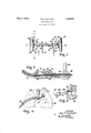
- Figure 1 is a top plan view of the front part of an automobile chassis, showing the novel operating mechanism connecting the front brakes;
- Figure 2 is a partial section on the line 2-2 of Figure 1, showing the means for operating the conduit;
- Figure 3 is a partial section on the line 33 of Figure 1, showing one of the brakes in elevation;
- Figure 4 is a partial section corresponding to Figure 3, but showing the operating mech anism supported by the chassis frame instead of by the opposite brake.
- the chassis illustrated includes the usual frame 10, supported by suitable springs on a front axle 12 and a rear axle (not shown) carried by road wheels 14 having brakes 16.
- Each brake may be provided, at the open side of the brake drum, with a suitable support such as a backing plate 18 carrying the friction means of the brake, and preferably supporting also an applying device such as a brake-applying cam 20 provided with a camshaft 22 having an operating crank arm or lever 24, on the outside of the backing plate in this particular arrangement.
- a cable 26, or an equivalent flexible tension element is fixedly secured at its ends to the two brakes, for example by having enlarged
- the inner ends of conduits 30 have fittings slidably arranged in parts 34- clamped to the axle by means such as U-bolts 36.
- F ittings 32 are keyed to parts 34;, to prevent turning, as shown in Figure 2.
- the tension element 26 is housed in a rigid 7 conduitlS slidably supported andjournalcdat its ends in parts 3%,the rigid conduit-38 and the two fittings 32 having interengaging spiral.
- Brake mechanism comprising, in combination, a wheel having a brake, a support, a tension element supported by said support and having its end mounted on said brake, an 100"- icnt flexibility not to interfere with the applying device carried by the brake adjacent the end of the tension element, and a compression conduit sleeved on the tension element and movable along the tension element lengthwise to operate said applying device.
- Brake mechanism comprising, in combinatlon, a wheel having a brake, a support, a tension element supported by said support and having its end fixedly secured to said brake, an applying ClV1CeC2L1'I'18Cl by the brake adjacent the end of the tension element, and a compression conduit sleeved on the'tens1on element and movable along the tension 16 element lengthwise to operate said applying device.
- Brake mechanism comprising, in combination, a wheel having a brake, a tension element held at its ends and one of whose ends 20 ,is at said brake, and a flexible compression conduit sleeved on the tension element and shiftable lengthwise thereon 'to apply the.
- a. lirake mechanism comprising, in. combination, a wheel having a brake, a tension "element held at its ends and one of whose ends is at said brake, a flexible compression conduit sleeved on the tension element and shiftable lengthwise thereon, andv a brake-apply- Icing lever engaged by the end of said condnit and operated by lengthwise movement there- Brake mechanism comprising, in combination, two wheels having brakes, a tension .35 ,ele1nent held at its ends and extending be tween the two brakes, conduits sleeved on said element, and means for forcing said conduits lengthwise of the tension element to apply the brakes.
- Brake mechanism comprising, in combination, two wheels having brakes, an applying device for each brake, a tension ele ment held at its ends and extending etween the two brakes, conduits sleeved on said ele- 45,1nent and engaging respectively said applying devices, and means for forcing said conduits apart lengthwise along the tension element to apply the brakes.
- .tcge her with a chassis frame, and comprising, in combination therewith, a flexible tension element held at 1ts opposite ends by the brake and. the chassis frame, an applying device for the brake adjacent the brake end of I said element, and a compression conduit sleeved on said element and movable lengthwise of said element to'operate the applying device.
- a chassis frame comprising, in combination therewith, a flexible tension element held at its opposite ends by the brake and the chassis frame, an applying device for the brake'adjacent the brake end of said element, a compression conduit sleeved on said element and movable lengthwise of said element and engaging the applying device, and means for sliding the conduit lengthwise along the tension element to operate the applying device.
- Brake mechanism comprising, in combination,two wheels having brakes, an applying device for each brake, a tension element held at its ends and extending between the two brakes, conduits sleeved on said element and engaging respectively said applying devices, and means for forcing said conduits apart lengthwise along the tension element to apply the brakes, said means being permitted to float in a direction lengthwise of the tension element in order to balance the pressures on, the brakes. through said conduits.
- a vehicle having a wheel with a brake together with achassis frame, and compris bination, a wheel having a brake, a tension element held at its ends and one of whose ends is at saidv brake, a flexible compression conduit sleeved on the tension element, and means for shifting said compression conduit lengthwise on said tension element to apply the brake.
Landscapes
- Engineering & Computer Science (AREA)
- Transportation (AREA)
- Mechanical Engineering (AREA)
- Braking Arrangements (AREA)
- Transmission Of Braking Force In Braking Systems (AREA)
Description
May 9, 1933. R. s. SANFORD BRAKE MECHANI SM Filed April 27, 1929 I t Il'il vlllllllglllllllllll llll III/[IIIIIIIIIIIi/I'IIIIIA IIIIIIIIIIIIIIIIIIIIIIIIM fllgllllllllllllllllqlll m IN VEN TOR BY 1& 9 8.801221%?41 A TTORNE Y Patented May 9, 1933 UNITED STATES PATENT men BOY S. SANFORD, OF SOUTH BEND, INDIANA, ASSIGNOR TO BENDIX BRAKE COMPANY, OF SOUTH BEND, INDIANA, A CORPORATION OF ILLINOIS BRAKE MECHANISM Application filed April 27, 1929. Serial N0. 358,488.
This invention relates to brakes, and is illustrated as embodied in novel operating mechanism for front automobile brakes. An object of the invention is to simplify the operating mechanism, by utilizing a flexible Bowden conduit which is shifted lengthwise of its cable or equivalent tension element to apply the brake. Preferably the tension element is held at its ends, being secured to two opposite brakes, or having one end secured to the brake and the other to the chassis frame, and the conduit for each brake is slidably mounted thereon in engagement with a cam lever or an equivalent brake-applying device.
The above and other objects and features of the invention, including various novel and desirable structural arragements will be apparent from the following description of the illustrative embodiments shown in the accompanying drawing, in which:
Figure 1 is a top plan view of the front part of an automobile chassis, showing the novel operating mechanism connecting the front brakes;
Figure 2 is a partial section on the line 2-2 of Figure 1, showing the means for operating the conduit;
Figure 3 is a partial section on the line 33 of Figure 1, showing one of the brakes in elevation; and
Figure 4 is a partial section corresponding to Figure 3, but showing the operating mech anism supported by the chassis frame instead of by the opposite brake.
The chassis illustrated includes the usual frame 10, supported by suitable springs on a front axle 12 and a rear axle (not shown) carried by road wheels 14 having brakes 16. Each brake may be provided, at the open side of the brake drum, with a suitable support such as a backing plate 18 carrying the friction means of the brake, and preferably supporting also an applying device such as a brake-applying cam 20 provided with a camshaft 22 having an operating crank arm or lever 24, on the outside of the backing plate in this particular arrangement.
A cable 26, or an equivalent flexible tension element, is fixedly secured at its ends to the two brakes, for example by having enlarged The inner ends of conduits 30 have fittings slidably arranged in parts 34- clamped to the axle by means such as U-bolts 36. F ittings 32 are keyed to parts 34;, to prevent turning, as shown in Figure 2. Between fittings 82, the tension element 26 is housed in a rigid 7 conduitlS slidably supported andjournalcdat its ends in parts 3%,the rigid conduit-38 and the two fittings 32 having interengaging spiral. or cam-shaped ends so that turning the rigid conduit 38, by means of its operating lever 4-0 connected to the usual operatinglinkage 4-2, serves to force the two flexible conduits 3O apart lengthwise of the tension element 26, to apply the two brakes. Since the rigid conduit 38 can float lengthwise, the pressures on the two brakes are balanced or equalized against each other. I
The arrangement of Figure 4 differs from that described above in that the tension element 126 is connected at its rear end to the chassis frame 10 instead of to the other brake, and the flexible conduit 130 is slid lengthwise thereof to apply the brake by means such as a lever 50 pivoted on the frame and op-' erated by the usual linkage 52.
While two illustrative embodiments have been described in detail, it is not my intention to limit the scope of the invention to those particular embodiments, or otherwise than by the terms of the appended claims.
I claim: 7 s v i 1. Brake mechanism comprising, in combination, a wheel having a brake, a support, a tension element supported by said support and having its end mounted on said brake, an 100"- icnt flexibility not to interfere with the applying device carried by the brake adjacent the end of the tension element, and a compression conduit sleeved on the tension element and movable along the tension element lengthwise to operate said applying device.
2. Brake mechanism comprising, in combinatlon, a wheel having a brake, a support, a tension element supported by said support and having its end fixedly secured to said brake, an applying ClV1CeC2L1'I'18Cl by the brake adjacent the end of the tension element, and a compression conduit sleeved on the'tens1on element and movable along the tension 16 element lengthwise to operate said applying device.
3. Brake mechanism comprising, in combination, a wheel having a brake, a tension element held at its ends and one of whose ends 20 ,is at said brake, and a flexible compression conduit sleeved on the tension element and shiftable lengthwise thereon 'to apply the.
brake.
a. lirake mechanism comprising, in. combination, a wheel having a brake, a tension "element held at its ends and one of whose ends is at said brake, a flexible compression conduit sleeved on the tension element and shiftable lengthwise thereon, andv a brake-apply- Icing lever engaged by the end of said condnit and operated by lengthwise movement there- Brake mechanism comprising, in combination, two wheels having brakes, a tension .35 ,ele1nent held at its ends and extending be tween the two brakes, conduits sleeved on said element, and means for forcing said conduits lengthwise of the tension element to apply the brakes.
40 6. Brake mechanism comprising, in combination, two wheels having brakes, an applying device for each brake, a tension ele ment held at its ends and extending etween the two brakes, conduits sleeved on said ele- 45,1nent and engaging respectively said applying devices, and means for forcing said conduits apart lengthwise along the tension element to apply the brakes.
7. A vehicle having a wheel with a brake,
.tcge her with a chassis frame, and comprising, in combination therewith, a flexible tension element held at 1ts opposite ends by the brake and. the chassis frame, an applying device for the brake adjacent the brake end of I said element, and a compression conduit sleeved on said element and movable lengthwise of said element to'operate the applying device.
8. A vehicle having a wheel with a bralre,
0 together with a chassis frame, and compris ing, in combination therewith, a flexible tension element held at its opposite ends by the brake and the chassis frame, an applying device for the brake'adjacent the brake end of said element, a compression conduit sleeved on said element and movable lengthwise of said element and engaging the applying device, and means for sliding the conduit lengthwise along the tension element to operate the applying device.
9. Brake mechanism comprising, in combination,two wheels having brakes, an applying device for each brake, a tension element held at its ends and extending between the two brakes, conduits sleeved on said element and engaging respectively said applying devices, and means for forcing said conduits apart lengthwise along the tension element to apply the brakes, said means being permitted to float in a direction lengthwise of the tension element in order to balance the pressures on, the brakes. through said conduits.
10. A vehicle having a wheel with a brake together with achassis frame, and compris bination, a wheel having a brake, a tension element held at its ends and one of whose ends is at saidv brake, a flexible compression conduit sleeved on the tension element, and means for shifting said compression conduit lengthwise on said tension element to apply the brake.
In testimony whereof, I have hereunto signed my name.
- ROY S. SANFORD.
Priority Applications (1)
| Application Number | Priority Date | Filing Date | Title |
|---|---|---|---|
| US358488A US1908451A (en) | 1929-04-27 | 1929-04-27 | Brake mechanism |
Applications Claiming Priority (1)
| Application Number | Priority Date | Filing Date | Title |
|---|---|---|---|
| US358488A US1908451A (en) | 1929-04-27 | 1929-04-27 | Brake mechanism |
Publications (1)
| Publication Number | Publication Date |
|---|---|
| US1908451A true US1908451A (en) | 1933-05-09 |
Family
ID=23409847
Family Applications (1)
| Application Number | Title | Priority Date | Filing Date |
|---|---|---|---|
| US358488A Expired - Lifetime US1908451A (en) | 1929-04-27 | 1929-04-27 | Brake mechanism |
Country Status (1)
| Country | Link |
|---|---|
| US (1) | US1908451A (en) |
Cited By (1)
| Publication number | Priority date | Publication date | Assignee | Title |
|---|---|---|---|---|
| DE102016225471A1 (en) * | 2016-12-19 | 2018-06-21 | Volkswagen Aktiengesellschaft | Handbrake cable |
-
1929
- 1929-04-27 US US358488A patent/US1908451A/en not_active Expired - Lifetime
Cited By (2)
| Publication number | Priority date | Publication date | Assignee | Title |
|---|---|---|---|---|
| DE102016225471A1 (en) * | 2016-12-19 | 2018-06-21 | Volkswagen Aktiengesellschaft | Handbrake cable |
| DE102016225471B4 (en) | 2016-12-19 | 2020-06-10 | Volkswagen Aktiengesellschaft | Hand brake cable device |
Similar Documents
| Publication | Publication Date | Title |
|---|---|---|
| US1908451A (en) | Brake mechanism | |
| US1771832A (en) | Brake-operating mechanism | |
| US1598807A (en) | Braking system | |
| US1964185A (en) | Brake-operating mechanism | |
| US1811172A (en) | Brake equalizer | |
| US1855407A (en) | Brake | |
| US1825680A (en) | Brake-operating connection | |
| US1723646A (en) | Brake-operating connection | |
| US1686360A (en) | Operating connection | |
| US2091005A (en) | Vehicle brake apparatus | |
| US1872953A (en) | Brake-operating connection | |
| US2001933A (en) | Brake | |
| US1947880A (en) | Brake | |
| US1598174A (en) | Attachment for automobile brakes | |
| US2146159A (en) | Brake mechanism | |
| US1696951A (en) | Poration | |
| US1966140A (en) | Brake | |
| US1943841A (en) | Brake | |
| US1936910A (en) | Brake-operating means | |
| US1411664A (en) | Vehicle brake | |
| US1545934A (en) | Motor vehicle | |
| US1812021A (en) | Brake operating connection | |
| US1790672A (en) | lyford | |
| US1752516A (en) | Brake | |
| US1974536A (en) | Brake |