US1908443A - Brake shoe - Google Patents
Brake shoe Download PDFInfo
- Publication number
- US1908443A US1908443A US557076A US55707631A US1908443A US 1908443 A US1908443 A US 1908443A US 557076 A US557076 A US 557076A US 55707631 A US55707631 A US 55707631A US 1908443 A US1908443 A US 1908443A
- Authority
- US
- United States
- Prior art keywords
- shoe
- brake shoe
- members
- brake
- depressions
- Prior art date
- Legal status (The legal status is an assumption and is not a legal conclusion. Google has not performed a legal analysis and makes no representation as to the accuracy of the status listed.)
- Expired - Lifetime
Links
- 230000003014 reinforcing effect Effects 0.000 description 6
- 238000010276 construction Methods 0.000 description 4
- 238000003466 welding Methods 0.000 description 3
- 239000002184 metal Substances 0.000 description 2
- 239000002783 friction material Substances 0.000 description 1
- 238000012986 modification Methods 0.000 description 1
- 230000004048 modification Effects 0.000 description 1
Images
Classifications
-
- F—MECHANICAL ENGINEERING; LIGHTING; HEATING; WEAPONS; BLASTING
- F16—ENGINEERING ELEMENTS AND UNITS; GENERAL MEASURES FOR PRODUCING AND MAINTAINING EFFECTIVE FUNCTIONING OF MACHINES OR INSTALLATIONS; THERMAL INSULATION IN GENERAL
- F16D—COUPLINGS FOR TRANSMITTING ROTATION; CLUTCHES; BRAKES
- F16D65/00—Parts or details
- F16D65/02—Braking members; Mounting thereof
- F16D65/04—Bands, shoes or pads; Pivots or supporting members therefor
- F16D65/08—Bands, shoes or pads; Pivots or supporting members therefor for internally-engaging brakes
Definitions
- This invention relates to shoes for brakes of the type in which a plurality of shoes are arranged to be moved outwardly into,
- the invention has for an object to provide a shoe of increased mechanical strength and of simple construction.
- Another object is to provide a shoe having an increased heat-dissipating surface whereby risk of distortion is' eliminated or reduced to negligible proportions.
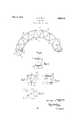
- Figure 1 is a side elevation of the im proved brake shoe
- Figure 2 is a section on line 22 ofv Figure 1;
- Figure 3 is a fragmentary side elevation of a modified form of the invention.
- Figure 4 is a section on line H of Figure 3.
- Figure 5 is a plan view of Figure 3.
- the illustrated form of the invention comprises an outer arcuate member 1, a concentric, inner, arcuate member 2, and a corrugated reinforcing member 3 which is bent to conform to the curvature of the members 1 and 2, as indicated in Figure 1.
- the meme ber 3 is arranged between the members 1 and 2, and the bends of the member 3 are rigidly connected to the members 1 and 2 at 4 preferably by spot welding. Alternatively, this connection may be effected by means of rivets, as indicated on one of the bends at 5.
- a bracket or pivot member 9 may be connected to one end of the shoe, the construction of the bracket depending on the type of brake in which the shoe is to be used.
- the bracket 9 has a hole 10 to receive a pivot bolt.
- the other end of the shoe may be designed to be engaged by a cam in the well known manner.
- Friction material may be mounted on the outer surface of member 1 in any known manner.
- the member 1 is provided with a staggered series of depressions 11 for engaging similar series of depressions 12 in the member 3 to facilitate the positioning of the member 1 on the member 3 preparatory to welding.
- holes 13 and 14 are'provided in the members 1 and 3 respectively to receive brake lining rivets.
- the invention is notlimited to any particular number of corrugations 3 nor to any particular angular arrangement thereof.
- the shoe is shown as being substantially semicircular, but it will be understood that the principle of the invention may be applied to shoes-of any other size.
- the improved shoe has increased mechanical strength on account of its trussed construction.
- the shoe dissipates heat more rapidly as it has a larger surface exposed to the air and therefore will not be appreciably distorted by heat generated during braking.
- a brake shoe comprising an arcuate outer member of strip metal, an inner member of strip metal, means for connecting the ends of said inner and outer members together, and a corrugated reinforcing member spacing said inner and outer members apart and having its bends connected thereto.
- a brake shoe comprising an arcuate outer member and an arcuate inner member connected at their ends, and a corrugated reinforcing member between said inner and outer members and having its bends rigidly connected thereto.
- a brake shoe as claimed in claim 2 wherein the ends of the inner and outer members are connected together and a bracket is connected to one of said ends.
- a brake shoe as claimed in claim 2 wherein a staggered series of depressions is provided in the outer member engaging a similar series of depressions in the bends of the reinforcing member, and wherein a staggered series of rivet holes is provided in the outer member and reinforcing member.
Landscapes
- Engineering & Computer Science (AREA)
- General Engineering & Computer Science (AREA)
- Mechanical Engineering (AREA)
- Braking Arrangements (AREA)
Description
May 9, 1933. A. POPE 1,908,443
BRAKE SHOE Filed Aug. 14 1951 INVENTQR: ARTHUR D. POPE.
BY ATTORNEY Patented May 9, 1933 ARTHUR 1). POPE, or OTTAWA, ONTARIO, CANADA, AssraNon. ro .nnNnrx BRAKE COM- PANY, or sor rn BEND, INDIANA, A ooBronAr oN or ILLINOIS BRAKE snon Application filed August 14, 1931. Serial No, 557,076.
This invention relates to shoes for brakes of the type in which a plurality of shoes are arranged to be moved outwardly into,
frictional engagement with cylindrical drum.
The invention has for an object to provide a shoe of increased mechanical strength and of simple construction.
Another object is to provide a shoe hav ing an increased heat-dissipating surface whereby risk of distortion is' eliminated or reduced to negligible proportions.
The invention consists in the construction, combination and arrangement of parts hereinafter described and more particularly pointed out in the appended claims.
Referring now to the accompanying drawing, which illustrates, by way of example, a convenient embodiment of the invention with certain modifications thereof,
Figure 1 is a side elevation of the im proved brake shoe;
Figure 2 is a section on line 22 ofv Figure 1;
Figure 3 is a fragmentary side elevation of a modified form of the invention;
Figure 4 is a section on line H of Figure 3, and
Figure 5 is a plan view of Figure 3.
The illustrated form of the invention comprises an outer arcuate member 1, a concentric, inner, arcuate member 2, and a corrugated reinforcing member 3 which is bent to conform to the curvature of the members 1 and 2, as indicated in Figure 1. The meme ber 3 is arranged between the members 1 and 2, and the bends of the member 3 are rigidly connected to the members 1 and 2 at 4 preferably by spot welding. Alternatively, this connection may be effected by means of rivets, as indicated on one of the bends at 5.
The end portions 6 and 7 of the members 1 and 2 are bent into engagement with each other and connected together by welding or by rivets 8.
A bracket or pivot member 9 may be connected to one end of the shoe, the construction of the bracket depending on the type of brake in which the shoe is to be used. In
the illustrated form of the invention the bracket 9 has a hole 10 to receive a pivot bolt. The other end of the shoe may be designed to be engaged by a cam in the well known manner.
Friction material, not shown, may be mounted on the outer surface of member 1 in any known manner.
Tn Figures 3, 4 and 5 the member 1 is provided with a staggered series of depressions 11 for engaging similar series of depressions 12 in the member 3 to facilitate the positioning of the member 1 on the member 3 preparatory to welding. Alternating with the depressions 11 and 2, holes 13 and 14: are'provided in the members 1 and 3 respectively to receive brake lining rivets.
The invention is notlimited to any particular number of corrugations 3 nor to any particular angular arrangement thereof.
The shoe is shown as being substantially semicircular, but it will be understood that the principle of the invention may be applied to shoes-of any other size.
The improved shoe has increased mechanical strength on account of its trussed construction. The shoe dissipates heat more rapidly as it has a larger surface exposed to the air and therefore will not be appreciably distorted by heat generated during braking.
What I claim is:
1. A brake shoe comprising an arcuate outer member of strip metal, an inner member of strip metal, means for connecting the ends of said inner and outer members together, and a corrugated reinforcing member spacing said inner and outer members apart and having its bends connected thereto.
2. A brake shoe comprising an arcuate outer member and an arcuate inner member connected at their ends, and a corrugated reinforcing member between said inner and outer members and having its bends rigidly connected thereto.
3. A brake shoe as claimed in claim 2, wherein the ends of the inner and outer members are connected together and a bracket is connected to one of said ends.
4. A brake shoe as claimed in claim 2,
wherein a staggered series of depressions is provided in the outer member engaging a similar series of depressions in the bends of the reinforcing member.
5. A brake shoe as claimed in claim 2, wherein a staggered series of depressions is provided in the outer member engaging a similar series of depressions in the bends of the reinforcing member, and wherein a staggered series of rivet holes is provided in the outer member and reinforcing member.
In testimony whereof I have affixed my 7 signature.
ARTHUR D. POPE.
Priority Applications (1)
| Application Number | Priority Date | Filing Date | Title |
|---|---|---|---|
| US557076A US1908443A (en) | 1931-08-14 | 1931-08-14 | Brake shoe |
Applications Claiming Priority (1)
| Application Number | Priority Date | Filing Date | Title |
|---|---|---|---|
| US557076A US1908443A (en) | 1931-08-14 | 1931-08-14 | Brake shoe |
Publications (1)
| Publication Number | Publication Date |
|---|---|
| US1908443A true US1908443A (en) | 1933-05-09 |
Family
ID=24223961
Family Applications (1)
| Application Number | Title | Priority Date | Filing Date |
|---|---|---|---|
| US557076A Expired - Lifetime US1908443A (en) | 1931-08-14 | 1931-08-14 | Brake shoe |
Country Status (1)
| Country | Link |
|---|---|
| US (1) | US1908443A (en) |
Cited By (2)
| Publication number | Priority date | Publication date | Assignee | Title |
|---|---|---|---|---|
| US2469402A (en) * | 1944-12-07 | 1949-05-10 | Warner Electric Brake Mfg Co | Brake anchor |
| DE10209001A1 (en) * | 2002-02-28 | 2003-09-25 | Bosch Gmbh Robert | drum brake |
-
1931
- 1931-08-14 US US557076A patent/US1908443A/en not_active Expired - Lifetime
Cited By (2)
| Publication number | Priority date | Publication date | Assignee | Title |
|---|---|---|---|---|
| US2469402A (en) * | 1944-12-07 | 1949-05-10 | Warner Electric Brake Mfg Co | Brake anchor |
| DE10209001A1 (en) * | 2002-02-28 | 2003-09-25 | Bosch Gmbh Robert | drum brake |
Similar Documents
| Publication | Publication Date | Title |
|---|---|---|
| US1908443A (en) | Brake shoe | |
| US9945435B2 (en) | Disk brake pad and disc brake assembly | |
| US1743412A (en) | Brake | |
| US1926064A (en) | Method of forming alpha brake band | |
| US1636003A (en) | Brake shoe | |
| US2247298A (en) | Multiple disk brake, coupling, and the like | |
| US2060891A (en) | Brake | |
| US1706635A (en) | Brake | |
| US1616583A (en) | Brake shoe | |
| US1857124A (en) | Friction brake | |
| US1865548A (en) | Brake shoe | |
| US2048921A (en) | Brake shoe | |
| US1781691A (en) | Brake | |
| US2105323A (en) | Brake | |
| US1647661A (en) | Brake shoe | |
| US1932899A (en) | Brake | |
| US2074723A (en) | Brake | |
| US1717936A (en) | Brake | |
| US1761231A (en) | Brake | |
| US1961930A (en) | Cushion clutch plate | |
| JP6644532B2 (en) | Drum brakes for vehicles | |
| US438673A (en) | Car-brake | |
| US1657884A (en) | Brake | |
| US1794857A (en) | Brake | |
| US2005874A (en) | Braking apparatus |