US1908424A - Signaling system and means - Google Patents
Signaling system and means Download PDFInfo
- Publication number
- US1908424A US1908424A US509908A US50990831A US1908424A US 1908424 A US1908424 A US 1908424A US 509908 A US509908 A US 509908A US 50990831 A US50990831 A US 50990831A US 1908424 A US1908424 A US 1908424A
- Authority
- US
- United States
- Prior art keywords
- contact
- contacts
- time
- electrical
- hand
- Prior art date
- Legal status (The legal status is an assumption and is not a legal conclusion. Google has not performed a legal analysis and makes no representation as to the accuracy of the status listed.)
- Expired - Lifetime
Links
- 230000011664 signaling Effects 0.000 title description 16
- 238000004804 winding Methods 0.000 description 12
- 239000004020 conductor Substances 0.000 description 8
- 230000033001 locomotion Effects 0.000 description 4
- 230000000694 effects Effects 0.000 description 3
- 230000015572 biosynthetic process Effects 0.000 description 2
- 238000010276 construction Methods 0.000 description 2
- 238000005304 joining Methods 0.000 description 2
- 238000004519 manufacturing process Methods 0.000 description 2
- 239000002184 metal Substances 0.000 description 2
- 238000000034 method Methods 0.000 description 2
- 238000002360 preparation method Methods 0.000 description 2
- 206010038743 Restlessness Diseases 0.000 description 1
- 238000007792 addition Methods 0.000 description 1
- 230000004075 alteration Effects 0.000 description 1
- 238000013459 approach Methods 0.000 description 1
- 230000003993 interaction Effects 0.000 description 1
- 230000000737 periodic effect Effects 0.000 description 1
- 238000000926 separation method Methods 0.000 description 1
- 238000006467 substitution reaction Methods 0.000 description 1
- 230000000007 visual effect Effects 0.000 description 1
Images
Classifications
-
- G—PHYSICS
- G04—HOROLOGY
- G04C—ELECTROMECHANICAL CLOCKS OR WATCHES
- G04C21/00—Producing acoustic time signals by electrical means
- G04C21/16—Producing acoustic time signals by electrical means producing the signals at adjustable fixed times
- G04C21/30—Producing acoustic time signals by electrical means producing the signals at adjustable fixed times with provision for a number of operations at different times, e.g. ringing the bells in a school
Definitions
- This invention relates to time signaling, cases must make some preparation for stopand more particularly to that class in which page of work, such as stopping machines at one signal is succeeded by a second one, there certain points in their operation, replacing being a comparatively short time interval tools in tool rooms, putting away personal between the two, and to means for such sigeffects, and such other activities prior to naling. actually leaving their work.
- the objects of this invention are to progroups of work people, there is a certain vide a specific cycle of signaling means for proportion which is known throughout the such signaling operated by a timing means manufacturing world as clock watchers.
- a device made to produce signals in accorddesired time which has parts and members ance with this invention will serve to elimiadapted to cause signals to be continued over nate the time losses and periodic inefficiencies some predetermined time period; produce a arising from these conditions.
- At some fixed secondary signal within some predetermined time say at five minutes before the hour of 15 period subsequent to the first signal, which stopping, an initial signal is given which two signals and their interval of separation may be of any kind, if it be observable or will constitute a cycle to provide this timing audible to all of the workmen.
- the second signal is given.
- the first duration. of signals and the time interval signal indicates that work may be gradually between the signals of a single cycle and stopped, machines may be slowed down and which will operate a quick break switch for their operation terminated at some specific an electric circuit to operate the signal means, or desired point. Tools may be laid away so that this may be connected directly with and the usual preparatory activities for stopthe time piece switch and its circuit-opening ping may begin. All operatives know that member without interposition of a relay, and a certain time interval is allowed for these in which current flow is neither started nor c ivi ies nd hat the second Signal Will be interrupted by either the hour or minute given at the exact time when [all work is to hand.
- this method of signaling is espeg 0f the next 0119- n y forms of cially designed to meet a condition with tune-Piece Operated members, i which the which all operators of factories and employhjlnds make and break l, W, d l- 45 ersof workmen are familiar, viz: the comfies have been experienced 1n Opemng the parative unrest and the slowing dow f contacts due to their very slow movement work as the noon hour or the end of the work way fI m and toward fixed contacts. Also, ingday approaches.
- the invention consistsin the novel and useful formation, construction, interrelation and combination of parts, members and features, as well as mode and methods of use thereof, and steps and performances taken and had, all as hereinafter described, shown in the drawing and finally pointed out in Claims In the drawings a. f.
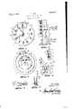
- Fig. 1 isa fronts'elevation of a time indicatingdevicei showing the indicating pointers, electrical contacts vwithwhich they cooplerate, and openings. varioiislyaplaced, into w ich .thecontacts. may be shifte for changingfhe time :period of signaling.
- V Fig.3 is a rear elevation .of .same..
- Fig. ,4 is. adiagrammatic showing of the essential parts and electrical connections.
- A is a disc or flat member, preferably vertical; B is a spindle passing through the surface of said member AZand at the center thereof.;anoving membersfiC, 1 ⁇ and -,E turn, about B as a center. Ihemain .spindle B is-surrounded by a concentric sleeve 16, and sleeve .16.is surrounded by a second concentrio sleeve 11.
- Movingmemher E which ls preferablly. in the ;form of a pointer, is affixed direct y to shaft B. and turns therewith..
- Moving member D which likewise is preferablv in the formof ,a pointer or indicator, isaflixed to sleeve 16, while moving member C similar to the other two moving members is attached to sleeve 17
- Spindle .B,and sleeves 16iand 17 are geared, or niechanically connected, so that they ,and t eir respective pointers turn around, central point B at different speeds.
- This character ofclock mechanism including the two clock hands forming no portion of the invention and being well-known, is not here depicted. s
- .---Pointe rs or clock-hands C and D are electrical onductors and. electrically connected t ge erat their pivots.
- ,Member E is preferably insulated from members C and D and is not an electrical conducting member.
- Buttons 10, which are electrical contacts, are attached to one face of member A in any convenient manner, as by using a shouldered button or screw, the head whereof projects from the surface of member A and the shank passing through any one of a number of holes ll arranged around said center B in circular formation and at such distance from B that the member contacts with any buttons placed in anyone of this said group of holes when the member in its rotation around B reaches the button or contact 10.
- a similar series of holes, 13, is formed on the surface of member A, but in a different plane from that whereon contact members 10 are placed.
- the plane for holes 13, in which contact members 14, are placed extends outwardly from the plane of the contact members 10 by a sufficient distance to enable member D to pass over member C and its accompanying contacts freely and without either of said members touching when they lie' in the same radial line.
- a pair of contact plates G and H, fastened in some predetermined position on member A, are arranged to be electrically connected when moving member 20 mounted on the end of the member E passes between them, as indicated more clearly in Figs. 5 and 6, the said plates and'member being-so positioned that members C and D cannot touch them in any part of the complete revolution of any of the members.
- the contact buttons for members C and D are preferably placed in the front face of the member A,
- the hand E is not a conductor and no current passes through or along it, the contact being made directly between plates G and H by interposition ofthe metal member 20. If these plates are of such length as to subtend an angle of 30 degrees, and member E moves 360 degrees in one minute, then plates G and H will be electrically connected through l/l2th of one minute, or for five seconds. Obviously no such definite and short time period of contact is possible with any time-piece having only the usual hour and minute hands.
- FIG. 4 shows diagrammatically one manner of operation of a device constructed in accordance with this invention.
- Incoming electric lines 22, 23, pass to the primary winding 24 of transformer T where the voltage of the current is stepped down and secondary winding 25 of transformer T becomes the immediate source of operating current.
- current passes from wire 26 to contact 10 and when member C touches contact 10 and member D simultaneously touches contact 14, there is an electrical path from winding 25 to plate G through contacts and members previous ly described and wire 28, leading from contact group 14 to plate G.
- any signal such'as L will be actuated, and when member 20 travels away from between its cooperating contact members G and H, the circuit to and through magnet Winding 30 is opened, magnet pull ceases and spring 33 pulls arm 32 of bellcrank K downward, opening the circuit between arm 35 and contact member 36 and stopping the signal.
- This latter may be visual as shown by dotted lines in Fig. 4.
- a contact of group 10 would be set at, say, 8 oclock.
- a contact of groupl4 would be set at approximately five minutes before the 12 numerical point or fifty-five minutes after the beginning of the hour, so that just prior to 7 :55, electrical contact would be formed, running from the source of electrical current to contact group 14 and plate G.
- member 20 enters between plates G and H, completing the circuit, so that the signal begins as, and through the means, previously described and will continue until member 20 passes from plates G and H, so that the period of signaling is just five seconds.
- This signal is notification to all workmen to make preparations for beginning actual work, and they are informed that within five minutes each operator must be at his place and have his tools or machines ready for commencing the work of the day. Since member 20 moves at a high velocity, and passes out from between spring-pressed contacts, the current quickly broken without drawing a visible are or pitting the contacts.
- member D has moved from the contact set at fiftyfive minutes after the beginning of the hour.
- member 20 will again pass between pdiites G and H, connecting them together, but the circuit is no longer continuous because member D makes no contact with any of its grou A ter a period of five minutes, member D will have moved to the next succeeding which is at the hour markor co-incident with the number 12 as shown in Fig. 1.
- Member C travels so slowly that at the end of five minutes it has moved only 2 degrees theoretically and actually much less, due to the resistance to movement of the hand caused by friction of rubbing against the contact so that usually the hour hand moves less than 1 degrees in five minutes. Hence at the end of five minutes it still touches the contact on which it was when the initial signal was given. Therefore, when the five minute period has passed, the electrical path through the magnet winding 30 is again completed by electrically joining plates G and H and the second signal for beginning of work, and which will again continue for five seconds, is given.
- this invention provides for a system and an apparatus which will give a preparatory signal, and which has the duration of indication limited to a comparatively short period as five seconds, and which will, a few minutes thereafter, give a second signal, the length of the second signal being a short predetermined time, and which will automatieally make these signals at exact predetermined hours, minutes and seconds of the twenty-four hours of any day and maintain them for equally exact predetermined periods.
- this appliance produces an efliciency and smoothness of operation in factories and the like, at initial and terminating periods of work which avoid confusion, increase production, and which show adefinite value in both earnings and satisfaction of the workmen themselves, which make it a desirable, in fact, almost necessary, instrument in any plant where the number of operatives exceeds five or six.
- a time-controlled electrical switching apparatus including a time piece, hour an minute hands thereon, two independent groups of electrical contacts, each group adapted to cooperate with one of said a third revolving member insulated from said time piece, a conducting element mounted on said third member, gearing between said third member and the time piece to drive said member with its conducting element faster than the minute hand, a fixed electrical contact adapted to cooperate with said conducting element, said contact having a length such that it is traversed by said element within a predetermined time, a conductor from one of said groups of contacts to said fixed contact, said groups of contacts with the hour and minute hands and the conductor and conducting element comprising a series electrical circuit adapted to be closed at predetermined times and so maintained while said conducting element continues to touch said fixed contact.
- a time-controlled electrical switching apparatus including a time piece, an hour hand and a minute hand moved'thereby; angularly spaced electrical contacts adapted to contact with said hour hand; angularly spaced electrical contacts adapted to contact with said minute hand; a third rotating member, gearing thereto from said time piece to revolve said member at a higher velocity than that of the minute hand, means insulating said third member from said hour and hands;
- a time-controlled electrical switching apparatus including a time piece, an hour hand and a minute hand thereon, each providing an electrical path along its length and electrically connected at their spindle ends, a group of angularly spaced electrical contacts adapted to contact with said hour hand; a second group of angularly spaced electrical contacts adapted to contact with said minute hand; a third member insulated from the apparatus and adapted to revolve, gearing between said member and the time piece whereby it is moved faster than the minute hand; a conducting element mounted on said third member, two fixed contacts cooperative with said conducting element to be periodically bridged thereby and having a predetermined length, an electrical connection joining one of the fixed contacts and a group of said hand contacts, said hands and contacts and connection forming a continuous electrical circuit from one group of contacts through the hands to the other group and thence to the moving conducting element when said moving members and their respective contacts are all simultaneously in engagement, said circuit being maintained through the time period required for the said conducting element to travel between its said fixed contacts.
- a timed electrical circuit closing and opening apparatus the combination of a time-piece, an hour hand, a minute hand and a third hand, all mounted on and driven by said time-piece, said hour and minute hands constituting electrical conducting paths and electrically connected at their spindle ends; a plurality of contacts electrically connected and angularly spaced around the axis of the time-piece adapted to cooperate with the hour hand, said contacts being adjustably mounted; a similar group of contacts adapted to cooperate with the minute hand, a conducting member mounted on said third hand and insulated from the other hands, and a third contact adapted to cooperate with the said moving conducting member, an electrical conductor between one of said groups of contacts and said third fixed contact, said parts and connections establishing a continuous electric circuit from one group of contacts through said hands to the other group and thence to said fixed contact through the conducting element When all threemoving members engage respectively with a cooperating contact.
- Means for closing an electrical circuit at predetermined time periods and for maintaining it closed during a fixed predetermined time interval and for opening said circuit including a time-piece, an hour hand thereon, a group of individual contacts cooperating therewith, a minute hand on the time-piecce, and a second group of individual contacts cooperating therewith, and a third hand; gearing between the third hand and said time-piece to turn the hand at a'higher speed than the minute hand; a conducting member mounted on said third hand, means for insulating said member, a pair of fixed, parallel, separated co-extensive contact elements adapted to accommodate said conducting member between them, thereby electrically connecting them throughout the time period fixed by the length of said elements and the speed of said third hand.
- Means for closing an electrical circuit at predetermined time periods and for maintaining it closed during a very short predetermined time interval and for opening said circuit including a time-piece, an hour hand driven thereby, a group of individual contacts cooperating therewith, a minute hand driven by the time-piece and a second group of individual contacts cooperating therewith, the said two hands being electrically conducting and connected, a third hand driven by the time-piece at a higher speed than the minute hand and insulated from the firstnamed hands, a pair of fixed, parallel, coextensive contact elements, a conducting member operated by said third hand and adapted to be moved between saidpaired elements, thereby electrically connectingthem throughout the time period fixed by the length of said elements and the speed of said third hand, an electrical work circuit, a connection from one of said groups of contacts to one of said paired contact elements; an electrical connection from the other of said contact elements to the work circuit, the entirety providing a continuous electrical circuit from one contact through its contacting hand to the other hand connected therewith, through said latter hand to one of its contacts
- Time-controlled electrical switching means including a time-piece, three movable members driven thereby, two thereof being electrically conducting along their lengths, a conducting element mounted on the third member and insulated from the other two members; electrical contacts for each of said first two conductingmembers and positioned for respective engagement with each said member, a double contact positioned to engage with said conducting element on said third member, an electrical conductor from one of said first mentioned electrical contacts to one part of said double contact, said parts and members forming a continuous electrical path when all three moving members simultaneously engage with their respective contacts.
- a timed switching mechanism including a time-piece, three hands driven thereby, each at a speed differing from thatof the others, a group of electrical contacts for one of said hands, a similar group for another of said hands, a conducting element mounted on the third of said hands, and insulated from the other hands; a contact positioned to be engaged by said conducting element, and an electrical conductor between one of said groups of electrical contacts and said contact cooperative with said conducting element.
Landscapes
- Physics & Mathematics (AREA)
- General Physics & Mathematics (AREA)
- Measurement Of Unknown Time Intervals (AREA)
Description
May 9, 1933. A 1,908,424
SIGNALING SYSTEM AND MEANS Filed Jan. 20, 1951 Patented May 9, 1933 1,908,424
UNITED STATES PATENT OFFICE AARON HILL, OF LOS ANGELES, CALIFORNIA SIGNALING SYSTEM AND MEANS Application filed January 20, 1931. Serial No. 509,908.
This invention relates to time signaling, cases must make some preparation for stopand more particularly to that class in which page of work, such as stopping machines at one signal is succeeded by a second one, there certain points in their operation, replacing being a comparatively short time interval tools in tool rooms, putting away personal between the two, and to means for such sigeffects, and such other activities prior to naling. actually leaving their work. Among all The objects of this invention are to progroups of work people, there is a certain vide a specific cycle of signaling means for proportion which is known throughout the such signaling operated by a timing means manufacturing world as clock watchers. which may be adjusted for signaling at any A device made to produce signals in accorddesired time which has parts and members ance with this invention will serve to elimiadapted to cause signals to be continued over nate the time losses and periodic inefficiencies some predetermined time period; produce a arising from these conditions. At some fixed secondary signal within some predetermined time, say at five minutes before the hour of 15 period subsequent to the first signal, which stopping, an initial signal is given which two signals and their interval of separation may be of any kind, if it be observable or will constitute a cycle to provide this timing audible to all of the workmen. After the device with a rapid moving member in order lapse of a short period -'of time, say five to insure accuracy of timing, exactness of minutes, the second signal is given. The first duration. of signals and the time interval signal indicates that work may be gradually between the signals of a single cycle and stopped, machines may be slowed down and which will operate a quick break switch for their operation terminated at some specific an electric circuit to operate the signal means, or desired point. Tools may be laid away so that this may be connected directly with and the usual preparatory activities for stopthe time piece switch and its circuit-opening ping may begin. All operatives know that member without interposition of a relay, and a certain time interval is allowed for these in which current flow is neither started nor c ivi ies nd hat the second Signal Will be interrupted by either the hour or minute given at the exact time when [all work is to hand. Further objects are to produce a sigstop and the employee is released from any 8 naling device which can be made at a low Of his no mal du ies. 0 cost,- which will be reliable and substantial, Obviously each occurrence of signaling rewithout complexities wherefrom disarrangequires a comple e cycle'including an initial ments might occur, and which i uitabl for signal, a period of intermission andasecond 35 any use to which such signal may be applied, signal, each of said signals and the inter.- and more specifically for factories and workmI iOII between them, having definite, preshopswhere a number of loye are determined time intervals, the sum of the i d t be i d t i t a d il t k three periods constituting the period of one at specified hours of th day, cycle Successive identical cycles may be 40 Other objects of this invention will appear p o ded for at desired intervals elapsing as this description proceeds. between the end of one cycle and the begin- Briefly, this method of signaling is espeg 0f the next 0119- n y forms of cially designed to meet a condition with tune-Piece Operated members, i which the which all operators of factories and employhjlnds make and break l, W, d l- 45 ersof workmen are familiar, viz: the comfies have been experienced 1n Opemng the parative unrest and the slowing dow f contacts due to their very slow movement work as the noon hour or the end of the work way fI m and toward fixed contacts. Also, ingday approaches. The workmen a itby reason of this slow movement exact time ing and expecting a signal indicating that periods of make and break become practi- 50 one of these hours has been reached, and they Cally i p sib e These dlfiicllltles are l desire to quit work immediately, and in many inated by the hlgh-speed element and quickbreak contact plates used in the signal timing device disclosed in this invention, by action of which current flow may be passed directly to the signal itself, and successfully interrupted without necessity of relays to do the actual switching of the signal current, the latter be'ng too large for interruption b a clock and contact. A
Wit the foregoing and other objects in view, the invention consistsin the novel and useful formation, construction, interrelation and combination of parts, members and features, as well as mode and methods of use thereof, and steps and performances taken and had, all as hereinafter described, shown in the drawing and finally pointed out in Claims In the drawings a. f.
.Fig. 1 isa fronts'elevation of a time indicatingdevicei showing the indicating pointers, electrical contacts vwithwhich they cooplerate, and openings. varioiislyaplaced, into w ich .thecontacts. may be shifte for changingfhe time :period of signaling.
. 2is a. side elevation in section of same,
showing a portion of the electrical appalfltuS.;' 2... V Fig.3 is a rear elevation .of .same..
Fig. ,4 is. adiagrammatic showing of the essential parts and electrical connections.
'Fig, ,.5.is a sectionalplan of, one pair of electrical contacts a and the contacting member between them. 1 ssmn 'ele on of s me.
In,the drawing, A is a disc or flat member, preferably vertical; B is a spindle passing through the surface of said member AZand at the center thereof.;anoving membersfiC, 1} and -,E turn, about B as a center. Ihemain .spindle B is-surrounded by a concentric sleeve 16, and sleeve .16.is surrounded by a second concentrio sleeve 11. Movingmemher E, which ls preferablly. in the ;form of a pointer, is affixed direct y to shaft B. and turns therewith.. Moving member D, which likewise is preferablv in the formof ,a pointer or indicator, isaflixed to sleeve 16, while moving member C similar to the other two moving members is attached to sleeve 17 Spindle .B,and sleeves 16iand 17 are geared, or niechanically connected, so that they ,and t eir respective pointers turn around, central point B at different speeds. This character ofclock mechanism, including the two clock hands forming no portion of the invention and being well-known, is not here depicted. s
.---Pointe rs or clock-hands C and D are electrical onductors and. electrically connected t ge erat their pivots. ,,Member E is preferably insulated from members C and D and is not an electrical conducting member. Buttons 10, which are electrical contacts, are attached to one face of member A in any convenient manner, as by using a shouldered button or screw, the head whereof projects from the surface of member A and the shank passing through any one of a number of holes ll arranged around said center B in circular formation and at such distance from B that the member contacts with any buttons placed in anyone of this said group of holes when the member in its rotation around B reaches the button or contact 10. A similar series of holes, 13, is formed on the surface of member A, but in a different plane from that whereon contact members 10 are placed. The plane for holes 13, in which contact members 14, are placed, extends outwardly from the plane of the contact members 10 by a sufficient distance to enable member D to pass over member C and its accompanying contacts freely and without either of said members touching when they lie' in the same radial line. A pair of contact plates G and H, fastened in some predetermined position on member A, are arranged to be electrically connected when moving member 20 mounted on the end of the member E passes between them, as indicated more clearly in Figs. 5 and 6, the said plates and'member being-so positioned that members C and D cannot touch them in any part of the complete revolution of any of the members. As shown, the contact buttons for members C and D are preferably placed in the front face of the member A,
whichlikewise is divided into twelve parts, each of said parts being numbered to resemble a clock face, and the moving members are geared and driven to simulate the hands of a clock, and at the same relative speeds, to wit: the revolving member C moves through 1/12th of a revolution in one hour, the revolving member D moves twelve times as fastas member C, and revolving member E moves much faster, at least 360 times asfastas moving member C. At the rear face of member A, all the holes of each group, as 10, are electrically connected together; hence, when member C touches one of the buttons 10 and member D touches one of the buttons 14, there is an electrical connection from contact 10 through the clock-hand C to pointer D and through pointer D to contact 14. i
From the common electrical connection for holes.1 4 is a wire leading to the contact platefG which in parallel with and identical in shape and size with similar contact plate H. These two plates are either of thin metal or spring supported and attached to any portion of the structure of flat member A or a casing surrounding it, but is diagrammatically indicated in the figures as being attached to the member A. These members or plates are separated by a small space or gap, and mounted to be slightly sprung further apart by means of a small conducted member or friction-reducing roller, 20, attached to the end of member E which electrically connects the two members G and H as long as member 20 remains between them. Member E having a definite angular speed, the length of time that plates G and H remain electrically connected is fixed by the length of this pair ofcontact plates. The hand E is not a conductor and no current passes through or along it, the contact being made directly between plates G and H by interposition ofthe metal member 20. If these plates are of such length as to subtend an angle of 30 degrees, and member E moves 360 degrees in one minute, then plates G and H will be electrically connected through l/l2th of one minute, or for five seconds. Obviously no such definite and short time period of contact is possible with any time-piece having only the usual hour and minute hands.
Fig. 4 shows diagrammatically one manner of operation of a device constructed in accordance with this invention. Incoming electric lines 22, 23, pass to the primary winding 24 of transformer T where the voltage of the current is stepped down and secondary winding 25 of transformer T becomes the immediate source of operating current. From winding 25, current passes via wires 26 and 27 to electrical timing device M. This rotates spindle B and the thereto connected and driven parts before described. Also, current passes from wire 26 to contact 10 and when member C touches contact 10 and member D simultaneously touches contact 14, there is an electrical path from winding 25 to plate G through contacts and members previous ly described and wire 28, leading from contact group 14 to plate G. If member 20, moved'by indicator E bridges the gap between G and H by the previously described means, current will fiow through winding 30 of magnet N via Wire 29 to one terminal of winding 30 and wire 31 to wire 27, and thereby to the other side of secondary winding 25. Current flow through magnet winding 30 will pull limb 32 of bellcrank K upward against the counter-pull of spring 33 so that arm 35 rotating about pivot 34 will contact with member 36. In this position an electric circuit is formed from Wire 22 through electric bell L back through contact 36, arm 35 and pivot 34, to the opposite side of the incoming circuit 23. Hence, when members C, and D and E are in specific positions, any signal such'as L will be actuated, and when member 20 travels away from between its cooperating contact members G and H, the circuit to and through magnet Winding 30 is opened, magnet pull ceases and spring 33 pulls arm 32 of bellcrank K downward, opening the circuit between arm 35 and contact member 36 and stopping the signal. This latter may be visual as shown by dotted lines in Fig. 4.
Obviously contact is made and broken only at plates G and H when current flow is begun or stopped. The much greater angular velocity of the high speed member E permits the close time regulation obtainable with this device, 'so that the circuit is established from contacts 10 to plate G before member 20 is passed into the gap between plates G and H, and the circuit still remains so connected at the end of the period of signaling and the current fiow is interrupted by the departure of member 20 from the ends of the plates. Hence contacts 10 and 14 only prepare the circuit for closing by member 20 at some time approximately near that for the beginning of the cycle of signaling, and they maintain their connections a sufiiciently long time to permit the signaling at the exact time required by the opening and closing of the gap between the two plates G and H. Obviously no exact successive short cyclical periods of signaling, interruption, and again signaling is possible by contact made by a hand traveling at the rate of only 6 degrees per minute, or one degree in ten seconds.
In practical use in a factory which begins work at 8 A. M., stops at 12, resumes work at l P. M., and stops at 6, the arrangement of the device would be as follows A contact of group 10 would be set at, say, 8 oclock. A contact of groupl4 would be set at approximately five minutes before the 12 numerical point or fifty-five minutes after the beginning of the hour, so that just prior to 7 :55, electrical contact would be formed, running from the source of electrical current to contact group 14 and plate G. At exactly 7: 55, member 20 enters between plates G and H, completing the circuit, so that the signal begins as, and through the means, previously described and will continue until member 20 passes from plates G and H, so that the period of signaling is just five seconds. This signal is notification to all workmen to make preparations for beginning actual work, and they are informed that within five minutes each operator must be at his place and have his tools or machines ready for commencing the work of the day. Since member 20 moves at a high velocity, and passes out from between spring-pressed contacts, the current quickly broken without drawing a visible are or pitting the contacts.
Subsequent to this initial signal, and within a short time, say to 4 minute, member D has moved from the contact set at fiftyfive minutes after the beginning of the hour.
' contact of this group,
' nal, of the cycle,
Within one minute after said first si al, member 20 will again pass between pdiites G and H, connecting them together, but the circuit is no longer continuous because member D makes no contact with any of its grou A ter a period of five minutes, member D will have moved to the next succeeding which is at the hour markor co-incident with the number 12 as shown in Fig. 1. Member C travels so slowly that at the end of five minutes it has moved only 2 degrees theoretically and actually much less, due to the resistance to movement of the hand caused by friction of rubbing against the contact so that usually the hour hand moves less than 1 degrees in five minutes. Hence at the end of five minutes it still touches the contact on which it was when the initial signal was given. Therefore, when the five minute period has passed, the electrical path through the magnet winding 30 is again completed by electrically joining plates G and H and the second signal for beginning of work, and which will again continue for five seconds, is given.
Subsequent to this second, or terminal, sigthe motion of the three members C, D and E has no effect and completes no circuit through the magnet winding because no contacts are placed in any of the groups 10 or 14 whereby the electrical circuit may be completed. At 11: 55, however, the cycle previously described is repeated, there being a contact for member C at about the 12 oclock point, the same fifty-five minute contact previously described for member D serving to close one part of the electrical path while connecting of plates G and H, completes the circuit through the magnet winding 30, thus giving the initial signal preparatory to stopping five minutes before the actual hour of ceasing work, just as has been set forth in describing the beginning of the work day. The time between successive cycles will be at least.30 times as long as the time of a cycle.
In brief, this invention provides for a system and an apparatus which will give a preparatory signal, and which has the duration of indication limited to a comparatively short period as five seconds, and which will, a few minutes thereafter, give a second signal, the length of the second signal being a short predetermined time, and which will automatieally make these signals at exact predetermined hours, minutes and seconds of the twenty-four hours of any day and maintain them for equally exact predetermined periods. In practice, it has been found that this appliance produces an efliciency and smoothness of operation in factories and the like, at initial and terminating periods of work which avoid confusion, increase production, and which show adefinite value in both earnings and satisfaction of the workmen themselves, which make it a desirable, in fact, almost necessary, instrument in any plant where the number of operatives exceeds five or six.
Applicant is aware of the existence of electrical time clocks which have a plurality of settings, but to his knowledge, no such complete apparatus as he has devised and here described has ever been produced or marketed.
Having described my invention in connection with illustrative embodiments, forms and arrangements of parts, it will be understood that many variants thereof are possible to those skilled in the art, and my invention, in its broader aspects, is not limited to the particular construction or application herein shown and described, as changes in size, proportions, configurations, arrangements, assemblage, interaction, juxtaposition and mechanical relations, as well as additions, omissions, substitutions, combinations and alterations of forms, parts, members, features and in the kind and order of operations and successive steps may be made without departing from the broad spirit of this invention.
I claim as my invention:
1. A time-controlled electrical switching apparatus, including a time piece, hour an minute hands thereon, two independent groups of electrical contacts, each group adapted to cooperate with one of said a third revolving member insulated from said time piece, a conducting element mounted on said third member, gearing between said third member and the time piece to drive said member with its conducting element faster than the minute hand, a fixed electrical contact adapted to cooperate with said conducting element, said contact having a length such that it is traversed by said element within a predetermined time, a conductor from one of said groups of contacts to said fixed contact, said groups of contacts with the hour and minute hands and the conductor and conducting element comprising a series electrical circuit adapted to be closed at predetermined times and so maintained while said conducting element continues to touch said fixed contact.
2. A time-controlled electrical switching apparatus, including a time piece, an hour hand and a minute hand moved'thereby; angularly spaced electrical contacts adapted to contact with said hour hand; angularly spaced electrical contacts adapted to contact with said minute hand; a third rotating member, gearing thereto from said time piece to revolve said member at a higher velocity than that of the minute hand, means insulating said third member from said hour and hands;,
minute hands, a conducting element mounted on said third member, two fixed contacts adapted to cooperate with said conducting element to be periodically bridged thereby and having a predetermined length, an electrical work circuit including said contacts, said hands and groups of contacts and fixed contacts and conducting member completing said electrical work circuit when the hands and said moving member are simultaneously in engagement with their respective contacts.
3. A time-controlled electrical switching apparatus including a time piece, an hour hand and a minute hand thereon, each providing an electrical path along its length and electrically connected at their spindle ends, a group of angularly spaced electrical contacts adapted to contact with said hour hand; a second group of angularly spaced electrical contacts adapted to contact with said minute hand; a third member insulated from the apparatus and adapted to revolve, gearing between said member and the time piece whereby it is moved faster than the minute hand; a conducting element mounted on said third member, two fixed contacts cooperative with said conducting element to be periodically bridged thereby and having a predetermined length, an electrical connection joining one of the fixed contacts and a group of said hand contacts, said hands and contacts and connection forming a continuous electrical circuit from one group of contacts through the hands to the other group and thence to the moving conducting element when said moving members and their respective contacts are all simultaneously in engagement, said circuit being maintained through the time period required for the said conducting element to travel between its said fixed contacts.
4. In a timed electrical circuit closing and opening apparatus, the combination of a time-piece, an hour hand, a minute hand and a third hand, all mounted on and driven by said time-piece, said hour and minute hands constituting electrical conducting paths and electrically connected at their spindle ends; a plurality of contacts electrically connected and angularly spaced around the axis of the time-piece adapted to cooperate with the hour hand, said contacts being adjustably mounted; a similar group of contacts adapted to cooperate with the minute hand, a conducting member mounted on said third hand and insulated from the other hands, and a third contact adapted to cooperate with the said moving conducting member, an electrical conductor between one of said groups of contacts and said third fixed contact, said parts and connections establishing a continuous electric circuit from one group of contacts through said hands to the other group and thence to said fixed contact through the conducting element When all threemoving members engage respectively with a cooperating contact.
5. Means for closing an electrical circuit at predetermined time periods and for maintaining it closed during a fixed predetermined time interval and for opening said circuit, including a time-piece, an hour hand thereon, a group of individual contacts cooperating therewith, a minute hand on the time-piecce, and a second group of individual contacts cooperating therewith, and a third hand; gearing between the third hand and said time-piece to turn the hand at a'higher speed than the minute hand; a conducting member mounted on said third hand, means for insulating said member, a pair of fixed, parallel, separated co-extensive contact elements adapted to accommodate said conducting member between them, thereby electrically connecting them throughout the time period fixed by the length of said elements and the speed of said third hand.
6. Means for closing an electrical circuit at predetermined time periods and for maintaining it closed during a very short predetermined time interval and for opening said circuit, including a time-piece, an hour hand driven thereby, a group of individual contacts cooperating therewith, a minute hand driven by the time-piece and a second group of individual contacts cooperating therewith, the said two hands being electrically conducting and connected, a third hand driven by the time-piece at a higher speed than the minute hand and insulated from the firstnamed hands, a pair of fixed, parallel, coextensive contact elements, a conducting member operated by said third hand and adapted to be moved between saidpaired elements, thereby electrically connectingthem throughout the time period fixed by the length of said elements and the speed of said third hand, an electrical work circuit, a connection from one of said groups of contacts to one of said paired contact elements; an electrical connection from the other of said contact elements to the work circuit, the entirety providing a continuous electrical circuit from one contact through its contacting hand to the other hand connected therewith, through said latter hand to one of its contacts, through the said electrical connection to its said fixed contact element, across said moving conducting member to the other of said contact elements and thence to the work circuit when all three said contact 010- sures are effected.
7 In a device of the character described, the combination of a time-piece, three coaxial members driven thereby, whereof two are electrical conductors and electrically connected together at the axis, a group of electrical contacts for each of said conducting members, each group positioned for the contacts to engage with its member, a conducting element mounted on the third memberand a fixed air of similar contact elements positione to engage simultaneously with said conducting-element, and a conductor between one ofsaid groups of contacts and one of said contact elements.
8. Time-controlled electrical switching means including a time-piece, three movable members driven thereby, two thereof being electrically conducting along their lengths, a conducting element mounted on the third member and insulated from the other two members; electrical contacts for each of said first two conductingmembers and positioned for respective engagement with each said member, a double contact positioned to engage with said conducting element on said third member, an electrical conductor from one of said first mentioned electrical contacts to one part of said double contact, said parts and members forming a continuous electrical path when all three moving members simultaneously engage with their respective contacts.
9,. A timed switching mechanism including a time-piece, three hands driven thereby, each at a speed differing from thatof the others, a group of electrical contacts for one of said hands, a similar group for another of said hands, a conducting element mounted on the third of said hands, and insulated from the other hands; a contact positioned to be engaged by said conducting element, and an electrical conductor between one of said groups of electrical contacts and said contact cooperative with said conducting element.
In testimony whereof, I have signed my nameto this specification at Los Angeles, Calif., this 14th day of January, 1931.
'- 1 AARON HILL.
Priority Applications (1)
| Application Number | Priority Date | Filing Date | Title |
|---|---|---|---|
| US509908A US1908424A (en) | 1931-01-20 | 1931-01-20 | Signaling system and means |
Applications Claiming Priority (1)
| Application Number | Priority Date | Filing Date | Title |
|---|---|---|---|
| US509908A US1908424A (en) | 1931-01-20 | 1931-01-20 | Signaling system and means |
Publications (1)
| Publication Number | Publication Date |
|---|---|
| US1908424A true US1908424A (en) | 1933-05-09 |
Family
ID=24028599
Family Applications (1)
| Application Number | Title | Priority Date | Filing Date |
|---|---|---|---|
| US509908A Expired - Lifetime US1908424A (en) | 1931-01-20 | 1931-01-20 | Signaling system and means |
Country Status (1)
| Country | Link |
|---|---|
| US (1) | US1908424A (en) |
Cited By (1)
| Publication number | Priority date | Publication date | Assignee | Title |
|---|---|---|---|---|
| US2459107A (en) * | 1940-12-03 | 1949-01-11 | Casco Products Corp | Drum type indicator alarm clock |
-
1931
- 1931-01-20 US US509908A patent/US1908424A/en not_active Expired - Lifetime
Cited By (1)
| Publication number | Priority date | Publication date | Assignee | Title |
|---|---|---|---|---|
| US2459107A (en) * | 1940-12-03 | 1949-01-11 | Casco Products Corp | Drum type indicator alarm clock |
Similar Documents
| Publication | Publication Date | Title |
|---|---|---|
| US2421986A (en) | Alarm clock and switch | |
| US1825382A (en) | Magnetic clock escapement | |
| US1908424A (en) | Signaling system and means | |
| US2329370A (en) | Rate-exhibiting device for integrating meters | |
| US2582285A (en) | Timer for causing brief actuations at prolonged intervals | |
| US2318969A (en) | Water distribution apparatus | |
| US2002433A (en) | Electrical actuating means fob | |
| US2767332A (en) | Electrical interval timer and control | |
| US2302626A (en) | Automatic timer | |
| US2301942A (en) | Timing mechanism | |
| US1791927A (en) | Program device | |
| US2195642A (en) | Radio timing device | |
| US2343951A (en) | Reversing door control and switch therefor | |
| US2489098A (en) | Process timer | |
| US2741601A (en) | Cloud seeding generator | |
| US2658329A (en) | Electrically wound and set watch | |
| US2311964A (en) | Electric clock | |
| US2451457A (en) | Traffic signal control system | |
| US2776384A (en) | Variable timing apparatus | |
| US2302625A (en) | Electrical timing apparatus | |
| US1999692A (en) | Electric clock | |
| US1475715A (en) | Typing-speed recorder | |
| US1922572A (en) | Automatic call mechanism | |
| SU45081A1 (en) | A device for indicating the frequency of electrical impulses | |
| US2281553A (en) | Variable cycle timer |