US1908353A - Butter tub setting up machine - Google Patents
Butter tub setting up machine Download PDFInfo
- Publication number
- US1908353A US1908353A US446328A US44632830A US1908353A US 1908353 A US1908353 A US 1908353A US 446328 A US446328 A US 446328A US 44632830 A US44632830 A US 44632830A US 1908353 A US1908353 A US 1908353A
- Authority
- US
- United States
- Prior art keywords
- staves
- tub
- machine
- cone
- shaft
- Prior art date
- Legal status (The legal status is an assumption and is not a legal conclusion. Google has not performed a legal analysis and makes no representation as to the accuracy of the status listed.)
- Expired - Lifetime
Links
- 235000014121 butter Nutrition 0.000 title description 8
- 238000010276 construction Methods 0.000 description 6
- 210000005069 ears Anatomy 0.000 description 4
- 238000000034 method Methods 0.000 description 4
- 239000011435 rock Substances 0.000 description 4
- 210000002105 tongue Anatomy 0.000 description 4
- 230000000994 depressogenic effect Effects 0.000 description 3
- 239000000428 dust Substances 0.000 description 3
- 239000000463 material Substances 0.000 description 3
- XEEYBQQBJWHFJM-UHFFFAOYSA-N Iron Chemical compound [Fe] XEEYBQQBJWHFJM-UHFFFAOYSA-N 0.000 description 2
- 238000005520 cutting process Methods 0.000 description 2
- 238000007599 discharging Methods 0.000 description 2
- 235000000396 iron Nutrition 0.000 description 2
- 238000012856 packing Methods 0.000 description 2
- 241000251468 Actinopterygii Species 0.000 description 1
- 241000239290 Araneae Species 0.000 description 1
- 241000271566 Aves Species 0.000 description 1
- 241000463176 Hinea Species 0.000 description 1
- 206010026749 Mania Diseases 0.000 description 1
- 241001149930 Protura <class> Species 0.000 description 1
- 241000287181 Sturnus vulgaris Species 0.000 description 1
- 230000001680 brushing effect Effects 0.000 description 1
- 230000006835 compression Effects 0.000 description 1
- 238000007906 compression Methods 0.000 description 1
- 230000005484 gravity Effects 0.000 description 1
- 229910052742 iron Inorganic materials 0.000 description 1
- 238000004519 manufacturing process Methods 0.000 description 1
- 239000002184 metal Substances 0.000 description 1
- 229910052751 metal Inorganic materials 0.000 description 1
- 230000010355 oscillation Effects 0.000 description 1
- 230000002250 progressing effect Effects 0.000 description 1
- 230000000284 resting effect Effects 0.000 description 1
- 238000005096 rolling process Methods 0.000 description 1
- 230000009183 running Effects 0.000 description 1
- 238000010408 sweeping Methods 0.000 description 1
- 239000002699 waste material Substances 0.000 description 1
Images


Classifications
-
- B—PERFORMING OPERATIONS; TRANSPORTING
- B27—WORKING OR PRESERVING WOOD OR SIMILAR MATERIAL; NAILING OR STAPLING MACHINES IN GENERAL
- B27M—WORKING OF WOOD NOT PROVIDED FOR IN SUBCLASSES B27B - B27L; MANUFACTURE OF SPECIFIC WOODEN ARTICLES
- B27M3/00—Manufacture or reconditioning of specific semi-finished or finished articles
- B27M3/34—Manufacture or reconditioning of specific semi-finished or finished articles of cases, trunks, or boxes, of wood or equivalent material which cannot satisfactorily be bent without softening ; Manufacture of cleats therefor
- B27M3/36—Machines or devices for attaching blanks together, e.g. for making wire-bound boxes
Definitions
- This invention relates to machines .for
- forming tubs and particularly butter tubs and the general object of the invention is to provide a machine of this character which includes a table upon which a set of staves may be laid out for a tub, a form upon which the staves are disposed and carried, means for shifting the form to carry the set of staves now disposed around the form into a pair of truss rings, means for withdrawing the form and then discharging the staves trussed by the truss rings out of the setting up machine so that the tub may be crozed and otherwise finished.
- a further object is to provide means whereby a setof staves may be laid out upon a table and the last set of the series may be cut or sawed upon a level which will be a true radius of the circle of the tub so that when the several staves are set together to form the tub, every joint will fit perfectly.
- a further object is to provide in a structure of this character, a table upon which the bundle of staves is laid out and cut as previously' stated and a form consisting of a hollow perforated cone upon which the staves are swept by the operator, this cone being connected to means whereby the air may be continuously withdrawn from the interior of the cone so that the staves shall be held upon the cone while the cone or form is shifted into a position to carry the arranged staves within the truss rings, the cone then being automatically withdrawn from the staves within the truss rings and the tub with its truss rings allowed to roll out of the machine.
- a further object is to provide means for shifting the staves longitudinally into correct position upon the form so as to bring theends of the staves in a single vertical plane.
- Another object is to provide means whereby a pair of truss rings may be fed autoy matically into the path of the reciprocating form and the staves assembled thereon prior to each forward movement of the form carrying the staves and provide means whereby the truss rings may be disposed upon an elevator and carried to the magazines or feeding elements above referred to.
- Figure 6 is a fragmentary plan view of the automatic stop and alliedparts
- Figure 7 is an end elevation of the structure shown in Figure 6;
- Figure 8 is a vertical sectional View through one of the racks
- Figure 9 is a fragmentary enlarged elevation of one end of themachine showing the stops for controlling the feed of the truss and popps and the discharge of the completed Figure 10 is an end elevation partly in section on an enlarged scale of part of the structure shown in Figure 7
- Figure 11 is asection on the line 1l11 of;
- Figure 12 is a section on the line 12 -12 of Figurell; Figure 12 is a fragmentary perspective View of the clutch key;
- Figure 13 is a section on the line 13-13 of Figure 1;
- Figure 14 is a fragmentary sectionthrougk one side rail and through the exhaust pipe and showlngthe thrust plate in elevation
- Figure 15 is a fragmentary elevation of the second section of the table showing the I stop actuating mechanism in elevation;
- 10 designates the longitudinally extending guides or rails which are operatively mounted upon legs 11 which form the frame of the machine, this frame carrying the table 12, i
- the section 14 as will be seen from Figure 13 is higher than the section 15 and extending downward from the surface of the section 14 to the upper surface of the section 15 is a downwardly curved portion 17 extending entirely across the sections 14 and 15. This .curved portion 17 has its butt end even with the end of the section 15 which confronts the section 14.
- a space is left between the sections 14 and 15 through which the circular saw 18 operates, this saw being mounted upon a swinging arm 19 supported on the member 13 forming part of the frame 13 supporting a motor 20, which motor is operatively connected to the saw mandrel 21 as by means of a balt or any other suitable mechanism to this en
- An adjustable counter-weight 22 acts to re turn the saw to a retracted position. This saw is operated constantly.
- the staves which are used to make tubs come to the operator in bundles. Each bundle constitutes approximately one set, that is suflicient for one spread on the form board 14 where the staves are inspected for quality by the person operating the saw.
- the stops 24 as illustrated in Figure 15, have upwardly and outwardly curved-portions projecting upward through the slots in the form board 15 and from a point just above this form board 15 extend straight downward and then laterally and carry the ears 25.
- These ears are mounted upon a rock shaft 26 having an arm connected 10 are mounted upon the frame of the machine in any suitable manner and constitute carriage guides.
- These guides are provided with longitudinally extending grooves 30 formed upon the inside faces of the rails 10.
- a cross head 31 Operating in these guide grooves 30 is a cross head 31.
- This cross head carries upon it the rod 32 which in turn engages with the air exhaust elbow 33.
- This elbow is angular in form and the upper end of the elbow is designed to be connected by a flexible trunk or like means to an air exhauster of any suitable character such as the cyclone in the plant which acts to draw the dust from the 7 machine.
- This cyclone creates a suction or partial vacuum in the elbow 33.
- the rear end of the elbow projects through a head 34 of a frustoconical former 35 of perforated sheet metal.
- the other end of this former issupported by means of a head 36 having a hub 37 with which the extremity of the rod 32 is rotatably engaged.
- the head 34 is provided with the radial inwardly offset spokes 38 constituting a spider, the hub 39 of which is rotatably mounted upon the rod 32.
- the hub 37 is also rotatable upon therod 32, but is held in place for longitudinal movement with the rod by means of the screw 40.
- the head 34 is annular in form so as to embrace the rear end of the elbow 33 and the inner edge of this annular head is grooved for the reception of an oil soaked felt washer 41 which con tacts with and has practically air-tight engagement with the rear end of the elbow
- the elbow 33 is provided with sleeves 42 through which the'rod 32 passes, each sleeve being held to the rod 32 by a set screw 43 or like means.
- the elbow is also provided with the downwardly extending ears 44 wlaereby it may be connected to an operating ro Disposed to surround the rearwardly extending portion of the elbow 33 is a thrust plate 45. This thrust platehas' an exterior diameter slightly larger than theadjacent end of the truncated form 35.
- the elbow has attached to it the longitudinally extending channel-shaped guides 46 (see Fig. 14) and the thrust plate has formed therewith the laterally disposed portions 47 having tongues engaging in said guides 46 and having laterally projecting tongues engaging in the guide grooves 30.
- the thrust plate is longitudinally guided upon the rails 10 and also with reference to the elbow, these grooves and tongues acting to hold the elbow in proper position.
- the thrust plate ismounted upon lateral upon these rods by set screws or like formed with laterally extending yoke link 56.
- lever 50 angular in form shown in Figure and its lower end slotted as at 51 the reception of a pivot pin 52.
- the upper end of this lever is formed to constitute bifurcations or forks at each end, which forks "age the rods 48 and are pinned thereto by pi;
- This le er is slottec.
- link 56 which at its rear end is pivoted to the cars 44 and at i forward end is srotted as at 57 to receive a pin 58 e ending through the walls of the slot 55.
- the lever 50 has slight movement inwardly relative to The lever is formed with a has.
- a clutch is disposed between the shaft 65 and the gear wheel 68 which clutch is adapted to be operated by means of a pedal so that when this pedal is depressed and the clutch is thrown in the shaft 65 will make one complete revolution and then the clutch will be automatically thrown out.
- This complete revolution of the shaft 65 and of the crank arm 66 carries the lever 50 rearward and the first action is to shift the complete carriage as one unit rearward through about half of its complete travel during which time pin 58 is traveling through the slot 57 in link 56.
- a stop 7 For the purpose of automatically turning the key against the action ofthe spring 77 into a position where it will engage the gear wheel 68 with the clutch sleeve, we provide a stop 7 9. frame of the machine and is urged into a position against a stop 81 by means of a contractile spring 82. The stop 79 is connected.
- the spring 82 will returnthe stop arm 79 to its clutch engaging position, and as the clutch sleeve completes its rotation, the arm 76 will engage the stop arm 79 and will be'lifted against the force of the spring 77 thus withdrawing the clutch and permitting the gear staves are disposed upon the form 35, the machine operator depresses the pedal 87. This causes the retraction of the connecting rod 61 and causes the lever 50 to move rearward carrying with it the thrust plate l5 and the cone 35.
- cone heads 36 and 34 rot-ate freely upon the shaft 32 and upon the elbow 33.
- Ball bearings may be used to support these heads 34 and 36 if desired.
- the brake drum 88 which is keyed on this shaft.
- This brake drum is surrounded by two brake shoes 89 and 90, the lower ends of these brake shoes being connected by means of the bolt 91 and the upper ends by a bolt and a spring 92 which urges the two sections toward each other.
- the brake shoe or section 90 of the brake band has a lateral section 93 engaged with the pivot pin 94 projecting from a bracket 95 mounted upon the frame of the machine so as to thus hold the brake from rotating with the brake drum.
- the pivot pin 94 carries upon it the tripping lever 96 and the I brake drum 88 is provided with an outwardly projecting pin 97 carrying a roller 98 which operates agalnst the free end of this lever, once for every revolution of the brake drum.
- This lever 96 is connected by a connecting rod 99 to an arm 100 projecting from a rock shaft 101 mounted in suitable bearings upon the frame of the machine.
- the frame of the machine is extended upward above this rock shaft 101 so as to form a cross bar 102 above the sh aft 101.
- the truss hoop trips 103 and 104 Mounted upon the shaft 101 are the truss hoop trips 103 and 104, the trip 103 carrying an outwardly. projecting curved finger 1 05.
- the trip 104 is swung by a link 106 connected. to an arm 107 (see Fig. 8) mounted upon the rack shaft 101 and the outer end of this trip 104 is pivotally mounted between two ears 108 on a transverse pivot pm.
- a spring 109 engaging with the arm 100 acts to rotate the shaft 101 in a direction to lift the finger 105 and simultaneously depress the inner end of the member 104 all for a purpose as will now appear.
- Each of the racks consists of 0p posed sections, each section having an approximately semi-circular periphery defining the outer wall 112 of each rack. Each section has the side walls 113. Each side wall 113 at its lower end is cut away at 114 to receive the tub mounted upon the coneshaped form The lower end of each rack rests upon the table 12 and extends out to each edge of this table.
- the inner wall of the rack is formed by the angularly related walls 115 (see Figure 8) connected at their inner ends by a curved portion 115a.
- the side walls are provided with the angle irons 116 and are also braced by the downwardly and laterally extending webs 117.
- the angle irons 116 are connected to the transversely extending bar 102.
- These stops 104 may be raised upward to release the completed tub and permit its discharge downward upon the tracks 118 but when the stops 104 are thus raised, a finger 105 is depressed to prevent the complete discharge of the completed tub but permit the tub to pass the stops 104. Then as the finger 105 is raised, the stops 104. will be lowered behind the completed tub and will engage the next pair of hoops.
- Ra ls 118 lead from the lower ends of the racks, these rails being channel-shaped to accommodate the Y hoops and permit the hooped tub to roll on down the tracks and be discharged.
- the hoops may be automatically returned to the racks after the tubs have been crozed and permanent hoops put on.
- the means simply consist ing in gravity conveyor C leading to the upper legs of the racks.
- This machine is driven by means of an electric motor 119 mounted upon the frame of the machine or mounted in any other suitable position, the shaft of which motor carries a pulley 119 (see Figure 3).
- This pulley is belted to a pulley mounted upon a worm shaft 121.
- the worm on this shaft engages a worm wheel (not shown) mounted upon the shaft which operates the pinion 69. Any other means for transmitting power may be used, however.
- the machine operator grasps the set at the extreme left and with a sweeping or brushing motion slides the entire set on to cone 35.
- the first stave of the series reaches the cone, it will be held more or less firmly upon the cone by reason of the partial vacuum formed in the interior of the cone and as the staves are pushed to the cone, the force exerted by the operator in pushing the staves on to the cone, will cause the cone to rotate, the successive staves being held to the cone by the said partial vacuum.
- the cone will continue to turn to allow the rest of the staves to follow right on around, these staves being held in place by a vacuum.
- the perforations 35 are disposed very closely adjacent each other over the entire cone and uniformly disposed over this cone and furthermore that these perforations are disposed in inclined lines longitudinally of the cone. This has been found to be necessary for the assembling and holding of the relatively narrow staves of a bucket.
- the cone in actual use is perforated with about 350 holes of one-quarter inch diameter and the arrangement of the holes is such that no two holes are directly in line along the longitudinal lines of the form. This permits a stave of extreme narrowness to be held firmly to the form.
- We have found in actual practice that in a form of large area, relatively few holes will not possibly accomplish the desired results since a narrow stave might possibly be disposed between two of the holes or between two of p the holes in the former that really controls the vacuum within the former.
- the next step in the operation of this machine is to force the tub into the temporary truss hoops.
- This is secured by operating the treadle 87 which clutches the shaft 65 to the gear 68 which is continually being turned by the motor and the rotation of the shaft 65 as before stated causes the thrust plate 45, perforated cone 35 carrying th staves, shaft 32 and elbow 33 and all parts composing the carriage to move together as one unit through approximately half of the complete travel, during which time the pin 58 is moving through the slot 57 in link 56.
- thrust plate 45 has set the staves firmly with in the truss hoop and all parts are ready to return to the starting point.
- the operator releases the pedal 87 immediately that themachine is started and, therefore, the cone with the staves is moved into the truss rings and the thrust platejams the staves firmly into the truss rings and upon the-return movement of the crank 66, completing the revolution of the shaft 65, the parts are returned to their normal position.
- the elbow 33 may be connected to the dust collecting system, that is, to the cyclone in any suitable manner, which will afford sufiicient flexibility to the connection as the elbow 33 is shifted.
- slotted link 56 is of considerable importance as this acts to cause the cone 35 to be drawn back toward the thrust plate 45 while the thrust'plate is forcing the staves into the *truss rings, thereby preventing the cone from sticking into the trussed tub.
- any suitable means such as foot power, steam power, compressed air, etc, may be used for actuating the carriage or otherwise driving the machine.
- Our machine greatly simplifies the process of laying out, setting up and trussing and controlling the size, form and shape of butter tubs and other objects of similar nature.
- the machine can be used in the manufacture of butter tubs, lard tubs, pails, fish kits, firkins or any circular package using staves or similar material, either tongued and grooved,'saw ointed, or smooth jointed in their construction.
- tubs have been manufactured by laying up the staves by hand which staves are set upright in a ring held by suitable supports.
- Another advantage of our invention is that it saves material inasmuch as the part cut oil may be used in the next set having been jointed properly by the cut-off saw, whereas by the old process, a poorly jointed stave was thrown away as waste.
- the air suction applied to the handling of the staves on the drum also acts as a cleaner or collectorfor the dust on the st'aves, thereby producing a more sanitary package for butter and other products.
- both units which are constituted one by the form 35, the shaft 32 and the elbow 33 and the other unit which consists of the thrust plate 45 and the rods 48 travel at different speeds. Both units are held in position by springs 49 and if it were not for connecting link 56, both units would travel forward and back as one unit, the length of travel by the complete unit being governed by the throw of the crank 66 and the connecting lever 50. Owing to the difference in the length of the lever between the pivots 52, 60 and 54, the length of travel of the complete cross head is greater than the throw of the crank 66.
- the first unit is pushed away from the second unit or thrust plate 45 in the same manner as in its forward motion, by reason of the differential motion of the two pivots 58 and 54.
- the pipe 3 which is connected to the form shown in Figure i is a relatively strong pipe ordinarily made of 5% inch sheet iron electrically'welded together, forming a strong and rigid unit.
- the sleeves 43 are welded into the pipe and the pipe is secured to the shaft 32 by means of set screws, thus pro-- viding an amply rigid construction for the slight pressure required to draw the form 35 from the tub.
- a table formed of two longitudinally curved sections, upon which a set res may he laid, the first section being higher than the succeeding section, pivoted stops mounted at the forward end of the second section normally extending straight upward hut rota hie into positi-on below the table suppo the states as they leave the table, manually operable means whereby r. stops may be lowered, a saw operating across the table and radial to the curve thereof, th distance between said saw and said stops being equal to the circumference of a completed tub the second section having at. the end adjacent said saw a convexly curved portion.
- a hollow stave su giportingr freely rotatable perforated form circular in cross section perforated over its entire surface, the perforations being relatively close to each other, means for continually exhausting the air from the interior of the form and a table discharging staves upon said form.
- a hollow stave supporting frusto--conical perforated form means for axially reciprocat ,ing said form, means for continually exhausting air from the interior of the form, and means for supporting truss rings in the path movement of and concentric to 'd f supporting a pair of truss in spa ed relation to each other and with their axes in alinement, and a stave receiving ft m axially reciprocable to carry the staves supported thereon into said truss rings and then withdraw the form.
- a tub setting up machine means for eporting a pair of truss rings in spaced rezation to each other and with their axes coincident, a frusto-conical form adapted to support the staves of a tub thereon, means for reciprocating said form to carry the stares on the form into said truss rings, a thrust plate disposed rearward of the form, and means for reciprocatingsaid thrust plate i epenzilently of the form to hold the staves Wlbll their ends evened up when the form is carried home within the truss rings.
- a hollow, o-conical perforated stave supporting TOllfl mounted for reciprocating, means for co: tinually exhausting air from said form to hold said staves thereon, means for supporting a p .urality of truss rings in the path of mover-entof said form and concentric thereto, means for reciprocating said form into a position within the truss rings and Wing form therefrom and a stave aiding thrust plate mounted rearward of '5.
- a pair of ss ring supporting racks disposed in relation to each other andopen on is, means for supporting the staves of a tub in assembled relation and forcing i' a es through said racks and into the se ilugS carried thereby, and means for detaining the assembled staves and truss rin e in the racks and operable to permit tl discharge therefrom.
- a pair of hollow truss ring racks having alined stave receiving og r ening's, each rack being open on one edge, a hollow stave supporting perforated frusto-conical form mounted for reiprocation into and out of said racks and is rings supported.
- a pair of truss'ring supporting racks open on their sides and ends and each open at one end, a reciprocating carriage, guide rails upon which said carriage reciprocates, a hollow stave supporting, frusto-conical perforated form mounted upon the carriage for reciprocating therewith and adapted when shifted forward to enter said racks and be disposed within the rings carried thereby, an exhznist pipe extending centrally from the rear end of said form and adapted to be connected to means whereby air may be continually exhausted from the interior of the form, an annular thrust plate surrounding said pipe and mounted for reciprocation relative thereto, a.
- lever operatively connected to the pipe and thus to the form, means connecting said lever to the thrust plate, the first and last named connecting means permitting a dif ferential motion between the thrust plate and the form, means for reciprocating said lever including a crank shaft having its crank operatively engaged with the lever, a gear loose thereon and driven from the source of power, manually operable means for engaging said gear with the crank shaft, and means acting automatically to release the connection of the gear when the crank shaft has made one complete rotation andthe carriage one complete reciprocation.
- a hollow stave supporting perforated frusto-conical form a rod upon which said form is mounted for rotation and with which the form is adapted to reciprocate, means for supporting a pair of truss rings in axial alinement with each other in the path of movement of said form, means for continuously exhausting the air from said form including an exhaust pipe entering the rear end of the form and with which the form has rotative airtight engagement, a thrust plate mounted upon the pipe for reciprocation relative thereto, manually controlled power operated means for reciprocating said rod to cause the exhaust pipe to carry the form into the truss rings and carry the thrust plate against the ends of the stave supported on the form and then retracting the thrust plate, the form and said rod, said means causing the retraction of the thrust plate slightly before the retraction of the form.
- a pair of racks each adapted to contain a series of truss rings, each rack being approximatetion into and out of said openings in the sides of the racks whereby to carry a series of staves into the truss rings and then with draw the form therefrom, and means acting upon a withdrawal of the form to automatically release the assembled tub to permit the discharge of the next pair of rings downward in said racks and stop said rings when they are in register with the openings in the sides of the racks.
- a pair of truss ring racks supporting a pair of truss rings in alinement, a stave supporting form reciprocatable into and out of said racks and the truss rings supported'therein, and means for reciprocating said form, including a shaft, means thereon for converting the rotary movement of the shaft into reciprocating movement of the form, a gear loose on the shaft, and operat1vely connected to a source of power, a manually actuatable clutch operatively engaging the gear with the shaft, or disengaging it therefrom, a continuously acting brake on the shaft, and means for automatically releasing said clutch when the shaft has made one complete revolution.
Landscapes
- Engineering & Computer Science (AREA)
- Life Sciences & Earth Sciences (AREA)
- Manufacturing & Machinery (AREA)
- Wood Science & Technology (AREA)
- Forests & Forestry (AREA)
- Conveying And Assembling Of Building Elements In Situ (AREA)
Description
BUTTER TUB SETTING UP MACHINE Filed April 22, 1930 May 9, 1933.
zfi
" zze v R. L. HINES ET AL '7 Sheets-Sheet 1 g I a a a a a a n n a.
, gwuentow Rlbfignes y 1933- R. L. HINES ET AL 1,908,353
BUTTER TUB SETTING UP MACHINE F iled April 22, 19:0 .7 Sheets-Sheet 2 R L,Hinea Jlfilum Qwoenlou y 9, 1933- R. L. HlNES ET AL 1,903,353
BUTTER TUB SETTING UP MACHINE Filed April 22, 1950 7 Sheets-Sheet 3 gwventoq y 1933- R. L. HINES ET AL 8,
BUTTER TUB SETTING UP MACHINE Filed April 22, 1930 7 Sheets-Sheet 4 ooooo ooooocoq m @0000 ouooooa x 0000 oo0o oo "3 jwventoq R.L Hi/1e5, 1452M? y 1933- R. L. HI NES ET AL 1,908,353
BUTTER TUB SETTING UP MACHINE Filed April 22, 1930 '7 Sheets-Sheet 5 oo aogoooooo Ill gwuwntoq ZZZ/45 1:7165, 771/, I Pllfilum y 9, 1933- R. L. HINES ET AL 1,908,353
BUTTER TUB SETTING UP MACHINE Filed April 22, 1950 7 Sheets-Sheet 6 k 7 6 L 7 manic,
B.L.H i116; cli/ lu m Patented May 9, 1933 UNITED STATE ASSIGNORS To Wisconsin BUTTER Tu POB-ATIOI'T or WISCONSIN s PATENT OFFICE I RAYMONDL. HINES, JOHN A. BLUM AND PAUL 1.. BLUM, or MARSHFiELD, Wiscons n} B 00., or MARSHFIELD, WISCONSIN, A con;
BUTTER TUB SETTING UP Macrame Application filed April 22,
This invention relates to machines .for
forming tubs and particularly butter tubs and the general object of the invention is to provide a machine of this character which includes a table upon which a set of staves may be laid out for a tub, a form upon which the staves are disposed and carried, means for shifting the form to carry the set of staves now disposed around the form into a pair of truss rings, means for withdrawing the form and then discharging the staves trussed by the truss rings out of the setting up machine so that the tub may be crozed and otherwise finished. V
A further object is to provide means whereby a setof staves may be laid out upon a table and the last set of the series may be cut or sawed upon a level which will be a true radius of the circle of the tub so that when the several staves are set together to form the tub, every joint will fit perfectly.
A further object is to provide in a structure of this character, a table upon which the bundle of staves is laid out and cut as previously' stated and a form consisting of a hollow perforated cone upon which the staves are swept by the operator, this cone being connected to means whereby the air may be continuously withdrawn from the interior of the cone so that the staves shall be held upon the cone while the cone or form is shifted into a position to carry the arranged staves within the truss rings, the cone then being automatically withdrawn from the staves within the truss rings and the tub with its truss rings allowed to roll out of the machine.
A further object is to provide means for shifting the staves longitudinally into correct position upon the form so as to bring theends of the staves in a single vertical plane.
Another object is to provide means whereby a pair of truss rings may be fed autoy matically into the path of the reciprocating form and the staves assembled thereon prior to each forward movement of the form carrying the staves and provide means whereby the truss rings may be disposed upon an elevator and carried to the magazines or feeding elements above referred to.
1930. Serial no; 446,328.
hoops and racks; 1
Figure 6 is a fragmentary plan view of the automatic stop and alliedparts;
Figure 7 is an end elevation of the structure shown in Figure 6;
Figure 8 is a vertical sectional View through one of the racks;
Figure 9 is a fragmentary enlarged elevation of one end of themachine showing the stops for controlling the feed of the truss and popps and the discharge of the completed Figure 10 is an end elevation partly in section on an enlarged scale of part of the structure shown in Figure 7 Figure 11 is asection on the line 1l11 of;
Figure 10;
Figure 12 is a section on the line 12 -12 ofFigurell; Figure 12 is a fragmentary perspective View of the clutch key;
Figure 13 is a section on the line 13-13 of Figure 1;
Figure 14: is a fragmentary sectionthrougk one side rail and through the exhaust pipe and showlngthe thrust plate in elevation Figure 15 is a fragmentary elevation of the second section of the table showing the I stop actuating mechanism in elevation;
Referring tothese drawings, 10 designates the longitudinally extending guides or rails which are operatively mounted upon legs 11 which form the frame of the machine, this frame carrying the table 12, i
Supported upon supporting legs 13 is'an arcuate assembling table formed of two sec'-' tions 14 and 15. At the rear ends of'the sec, I
Other objects will appear in the course.
the truss i tions 14 and 15 are disposed the curved form boards 16 to keep the staves in position. The section 14 as will be seen from Figure 13 is higher than the section 15 and extending downward from the surface of the section 14 to the upper surface of the section 15 is a downwardly curved portion 17 extending entirely across the sections 14 and 15. This .curved portion 17 has its butt end even with the end of the section 15 which confronts the section 14. A space is left between the sections 14 and 15 through which the circular saw 18 operates, this saw being mounted upon a swinging arm 19 supported on the member 13 forming part of the frame 13 supporting a motor 20, which motor is operatively connected to the saw mandrel 21 as by means of a balt or any other suitable mechanism to this en An adjustable counter-weight 22 acts to re turn the saw to a retracted position. This saw is operated constantly. The staves which are used to make tubs come to the operator in bundles. Each bundle constitutes approximately one set, that is suflicient for one spread on the form board 14 where the staves are inspected for quality by the person operating the saw. If there are any off-grade staves in the set, they are taken out and put into a stave box 23 and a good staveput in place. The set of staves is now swept or slid from section 14 on to section 15 until the first stave rests against adjustable stops 24 projecting up through slots in the extremity of section 15. v
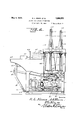
The means for operating these stops will be later stated. The last stave of the series will now extend somewhat over thesaw line or space between the sections 14 and 15, the last stave resting upon the curved portion 17. The operator then holds the stave to be cut firmly down on the curved portion 17 with his right hand while he draws the saw through the staves with his left hand, thus cutting the set on form board 15 to exact size. The downwardincline or curvature of the convexly curved portion 17 acts to support the stave at such an inclination to the horizontal that the saw 18 will cut the edge of the stave on the proper bevel. While the saw operator gets the next set spread out on the table section 14, the machine operator releases the stops 24 and sweeps or slides the entire set on to the form. The stops 24 as illustrated in Figure 15, have upwardly and outwardly curved-portions projecting upward through the slots in the form board 15 and from a point just above this form board 15 extend straight downward and then laterally and carry the ears 25. These ears are mounted upon a rock shaft 26 having an arm connected 10 are mounted upon the frame of the machine in any suitable manner and constitute carriage guides. These guides are provided with longitudinally extending grooves 30 formed upon the inside faces of the rails 10. Operating in these guide grooves 30 is a cross head 31. This cross head carries upon it the rod 32 which in turn engages with the air exhaust elbow 33. This elbow is angular in form and the upper end of the elbow is designed to be connected by a flexible trunk or like means to an air exhauster of any suitable character such as the cyclone in the plant which acts to draw the dust from the 7 machine.
This cyclone creates a suction or partial vacuum in the elbow 33. The rear end of the elbow projects through a head 34 of a frustoconical former 35 of perforated sheet metal. The other end of this former issupported by means of a head 36 having a hub 37 with which the extremity of the rod 32 is rotatably engaged. The head 34 is provided with the radial inwardly offset spokes 38 constituting a spider, the hub 39 of which is rotatably mounted upon the rod 32. The hub 37 is also rotatable upon therod 32, but is held in place for longitudinal movement with the rod by means of the screw 40. The head 34 is annular in form so as to embrace the rear end of the elbow 33 and the inner edge of this annular head is grooved for the reception of an oil soaked felt washer 41 which con tacts with and has practically air-tight engagement with the rear end of the elbow The elbow 33 is provided with sleeves 42 through which the'rod 32 passes, each sleeve being held to the rod 32 by a set screw 43 or like means. The elbow is also provided with the downwardly extending ears 44 wlaereby it may be connected to an operating ro Disposed to surround the rearwardly extending portion of the elbow 33 is a thrust plate 45. This thrust platehas' an exterior diameter slightly larger than theadjacent end of the truncated form 35. The elbow has attached to it the longitudinally extending channel-shaped guides 46 (see Fig. 14) and the thrust plate has formed therewith the laterally disposed portions 47 having tongues engaging in said guides 46 and having laterally projecting tongues engaging in the guide grooves 30. Thus the thrust plate is longitudinally guided upon the rails 10 and also with reference to the elbow, these grooves and tongues acting to hold the elbow in proper position. i
The thrust plate ismounted upon lateral upon these rods by set screws or like formed with laterally extending yoke link 56.
able bearing heads 67 to the rods 48 which extend forward and at their forward ends pass loosely through the cross head 31 and thus have sliding engagement in this cross head. The thrust plat is held means. Springs 49 each attached at one end to the cross h ad 31 at the other end are operatively connected to the thrust plate acting to urge the thrust plate toward the cross head.
Mour'ited upon the frame of the machine at the front thereof is a lever 50 angular in form shown in Figure and its lower end slotted as at 51 the reception of a pivot pin 52. The upper end of this lever is formed to constitute bifurcations or forks at each end, which forks "age the rods 48 and are pinned thereto by pi; This le er is slottec. at 55 and disposed in this slot is a link 56 which at its rear end is pivoted to the cars 44 and at i forward end is srotted as at 57 to receive a pin 58 e ending through the walls of the slot 55. Thus the lever 50 has slight movement inwardly relative to The lever is formed with a has. just below the slot having a pivot pin 60 extending therethrough to which the forward end of a reciprocating rod 61 is operatively connected. This connecting rod passes through a U-shapcd voke 62 which yoke is pivoted on the pivot pin 60 and the connecting rod carries the nuts 63 and a coiled compression spring 6% is disposed between the end of the yoke 62 and these nuts so as to I constitute a cushionin s rin Disposed below the table 12 and at the rear of the machine is a transversely extending shaft 65 carrying upon it a crank arm 66 which is operatively connected through suitconnecting rod 61. Mounted loosely upon this shaft 65 is a gear wheel 68 which. meshes with a driving pinion 69 mounted upon a shaft 70 driven from any suit-able source of power. Generally speaking, a clutch is disposed between the shaft 65 and the gear wheel 68 which clutch is adapted to be operated by means of a pedal so that when this pedal is depressed and the clutch is thrown in the shaft 65 will make one complete revolution and then the clutch will be automatically thrown out. This complete revolution of the shaft 65 and of the crank arm 66 carries the lever 50 rearward and the first action is to shift the complete carriage as one unit rearward through about half of its complete travel during which time pin 58 is traveling through the slot 57 in link 56. At this point the parts 31, 32, 33 and 35 which are connected to link 56 begin to retreat toward thrust plate 45, break- 'plate forces the staves tightly in position between the truss hoop rings and then the reverse stroke of'the crank arm66 carries the form out from within the formed staves and all the parts are brought back to the initial position shown in Figure 4.
In order to providemeans for intermittently giving one rotation to the shaft 65 and to the crank arm 66, I mount the gear wheel 68 loosely upon a clutch gear sleeve 71. This sleeve is keyed upon the shaft 65 and at one end is provided with a head 72. This.
engage with a recess 78 formed in the inner. margin of the gear wheel '68. When the arm' 76 is lifted upward against the action of the spring 77, however, the key will be turned into such position that it no longer projects into the path of movement of the gear wheel 68 and at this time the gear wheel 68 rotates freely upon the clutch sleeve71.
For the purpose of automatically turning the key against the action ofthe spring 77 into a position where it will engage the gear wheel 68 with the clutch sleeve, we provide a stop 7 9. frame of the machine and is urged into a position against a stop 81 by means of a contractile spring 82. The stop 79 is connected.
by a llIlJ. 83 to a lever 84 pivoted upon the frame of the machine and the other end of this lever is connected by a connecting rod 85 to one arm 86 of a pedal 87. When this pedal is depressed, it withdraws the stop 79 from below the arm 7 6, thus permitting the spring 77 to shift the arm 76 into a direction to carry the key into interlocking engagement between the clutch sleeve and the gear wheel 68 and tien the gear wheel 68 and the shaft 65 will rotate together through one revolution. As soon as the operator releases the pedal 87, the spring 82 will returnthe stop arm 79 to its clutch engaging position, and as the clutch sleeve completes its rotation, the arm 76 will engage the stop arm 79 and will be'lifted against the force of the spring 77 thus withdrawing the clutch and permitting the gear staves are disposed upon the form 35, the machine operator depresses the pedal 87. This causes the retraction of the connecting rod 61 and causes the lever 50 to move rearward carrying with it the thrust plate l5 and the cone 35. The initial movement is given to the thrust plate which moves against the staves, evening the staves up, then the motion This stop is pivoted at 001113011 the- I is communicated to the rod 32, the elbow 33 and the form and the staves arranged upon the form are thrust into the temporary hoops with a force suihcient to jam the staves within the hoops and then the lever moves back again to its initial position and the form 35, thrust plate and the elbow are withdrawn and brought to their initial positions.
It will be understood, of course, that the cone heads 36 and 34 rot-ate freely upon the shaft 32 and upon the elbow 33. Ball bearings may be used to support these heads 34 and 36 if desired.
It is to be understood that when the staves S are placed upon the form 35, they project about one and one-half inches over the end of the cone or form. Then the lever 50 moves the thrust plate rearward, the link 56 which controls the movement of the cone travels with it at a slower rate. This difierence in the rate of motion of the plate and cone prevents the cone from sticking in the tub when the latter is forced into the truss rings carried by the truss ring racks now to be described. The thrust plate 45 does not under any circumstances, however, strike the conical form 35, but merely strikes the ends of the staves. Inasmuch as the elbow 33 has its sides provided with channels corresponding with inwardly projecting tongues on the thrust plate, this difference in length of travel is permitted.
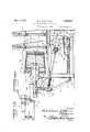
For the purpose of stopping the shaft when it has made one revolution, we mount upon the shaft the brake drum 88 which is keyed on this shaft. This brake drum is surrounded by two brake shoes 89 and 90, the lower ends of these brake shoes being connected by means of the bolt 91 and the upper ends by a bolt and a spring 92 which urges the two sections toward each other. The brake shoe or section 90 of the brake band has a lateral section 93 engaged with the pivot pin 94 projecting from a bracket 95 mounted upon the frame of the machine so as to thus hold the brake from rotating with the brake drum. The instant that the power is cut off from the shaft 65, the friction brake formed of the parts 89 and 90 will prevent any further movement of the shaft and thus the shaft is stopped when it has been given one complete revolution. The pivot pin 94 carries upon it the tripping lever 96 and the I brake drum 88 is provided with an outwardly projecting pin 97 carrying a roller 98 which operates agalnst the free end of this lever, once for every revolution of the brake drum.
This lever 96 is connected by a connecting rod 99 to an arm 100 projecting from a rock shaft 101 mounted in suitable bearings upon the frame of the machine.
As illustrated in Figure 9, the frame of the machine is extended upward above this rock shaft 101 so as to form a cross bar 102 above the sh aft 101. Mounted upon the shaft 101 are the truss hoop trips 103 and 104, the trip 103 carrying an outwardly. projecting curved finger 1 05. The trip 104 is swung by a link 106 connected. to an arm 107 (see Fig. 8) mounted upon the rack shaft 101 and the outer end of this trip 104 is pivotally mounted between two ears 108 on a transverse pivot pm.
A spring 109 engaging with the arm 100 acts to rotate the shaft 101 in a direction to lift the finger 105 and simultaneously depress the inner end of the member 104 all for a purpose as will now appear.
Mounted upon the table 12 are two spaced racks designated generally 110 and 111 designed to receive the truss hoops A and guide these truss hoops into such position that the cone shaped form and the staves assembled thereon may be forced into these temporary hoops A. Each of the racks consists of 0p posed sections, each section having an approximately semi-circular periphery defining the outer wall 112 of each rack. Each section has the side walls 113. Each side wall 113 at its lower end is cut away at 114 to receive the tub mounted upon the coneshaped form The lower end of each rack rests upon the table 12 and extends out to each edge of this table. The inner wall of the rack is formed by the angularly related walls 115 (see Figure 8) connected at their inner ends by a curved portion 115a. Thus the upper portion of the wall 115 forms the bottom of the upper leg of the rack while the lower portion of the wall 115 forms the top of the lower leg of the rack. The side walls are provided with the angle irons 116 and are also braced by the downwardly and laterally extending webs 117. The angle irons 116 are connected to the transversely extending bar 102. The hoops which are fed into the upper legs of the racks roll down the racksinto the lower legs thereof, as shown in Figure 8 and each forwardmost hoop is held against further downward movement and in alinement with a cut-away portion at 14 by the stops 104. These stops 104 may be raised upward to release the completed tub and permit its discharge downward upon the tracks 118 but when the stops 104 are thus raised, a finger 105 is depressed to prevent the complete discharge of the completed tub but permit the tub to pass the stops 104. Then as the finger 105 is raised, the stops 104. will be lowered behind the completed tub and will engage the next pair of hoops. Ra ls 118 lead from the lower ends of the racks, these rails being channel-shaped to accommodate the Y hoops and permit the hooped tub to roll on down the tracks and be discharged.
Preferably means are used whereby the hoops may be automatically returned to the racks after the tubs have been crozed and permanent hoops put on. We do not wish to be limited, however, to any specific means for thispurpose, the means simply consist ing in gravity conveyor C leading to the upper legs of the racks.
This machine is driven by means of an electric motor 119 mounted upon the frame of the machine or mounted in any other suitable position, the shaft of which motor carries a pulley 119 (see Figure 3). This pulley is belted to a pulley mounted upon a worm shaft 121. The worm on this shaft engages a worm wheel (not shown) mounted upon the shaft which operates the pinion 69. Any other means for transmitting power may be used, however.
It will be seen that in the operation of this machine, and assuming that the parts are in the position shown in Figure 4, the set ofstaves as before stated is spread out on the table section 14, where it is inspected, etc. Theset of staves is now shifted from the section 14 on to the section 15 so that the forwardmost stave is against the stops 24. The operator, holding the last stave of the series, then shifts the saw 18 lengthwise of this stave, cutting the stave so that the set will now fit accurately around the form 35. l Vhile the saw operator gets the next set spread on the table section 14, the machine operator pushes down the lever 28 which lowers the stops 24, these stops forming a bridge over the section 15 on to the cone 35. While the form board stops are held in this position with the left hand, the machine operator with his right hand grasps the set at the extreme left and with a sweeping or brushing motion slides the entire set on to cone 35. As the first stave of the series reaches the cone, it will be held more or less firmly upon the cone by reason of the partial vacuum formed in the interior of the cone and as the staves are pushed to the cone, the force exerted by the operator in pushing the staves on to the cone, will cause the cone to rotate, the successive staves being held to the cone by the said partial vacuum. After this initial movement of the cone,the cone will continue to turn to allow the rest of the staves to follow right on around, these staves being held in place by a vacuum.
Attention is particularlycalled to the factthat the perforations 35 are disposed very closely adjacent each other over the entire cone and uniformly disposed over this cone and furthermore that these perforations are disposed in inclined lines longitudinally of the cone. This has been found to be necessary for the assembling and holding of the relatively narrow staves of a bucket. As amatter of fact, the cone in actual use is perforated with about 350 holes of one-quarter inch diameter and the arrangement of the holes is such that no two holes are directly in line along the longitudinal lines of the form. This permits a stave of extreme narrowness to be held firmly to the form. We have found in actual practice that in a form of large area, relatively few holes will not possibly accomplish the desired results since a narrow stave might possibly be disposed between two of the holes or between two of p the holes in the former that really controls the vacuum within the former.
Th staves having been placed upon the cone 35 and held in place by the partial vacuum in the interior, the next step in the operation of this machine is to force the tub into the temporary truss hoops. Thisis secured by operating the treadle 87 which clutches the shaft 65 to the gear 68 which is continually being turned by the motor and the rotation of the shaft 65 as before stated causes the thrust plate 45, perforated cone 35 carrying th staves, shaft 32 and elbow 33 and all parts composing the carriage to move together as one unit through approximately half of the complete travel, during which time the pin 58 is moving through the slot 57 in link 56. At this point, the carriage carrying the staves has entered the truss hoop and is progressing toward its objective, the pin 58 having reached the extremity of slot 57 in link 56 and being constrained for further movement and this draws the elbow 33, shaft 32 and cone 35 which carries the staves (all of which are connectedas one unit to link 56) toward thrust plate 45. As the movement continues the ends of the staves are brought firmly against the thrust plate and thecone 35 is drawn back until the vacuum is broken. At this point, of course, the carriage has reached the end of its travel, the
It is to be particularly noted that the slotted link 56 is of considerable importance as this acts to cause the cone 35 to be drawn back toward the thrust plate 45 while the thrust'plate is forcing the staves into the *truss rings, thereby preventing the cone from sticking into the trussed tub.
While we do not wish to be limited to this, attention is also called to the fact that preferably the perforations in the cone 35 run ning lengthwise of the cone will be on a slightly spiral line and under these circum stances there will always be enough perforations to cause even narrow strives to stay on the cone. 7
It will be understood, of course, that any suitable means such as foot power, steam power, compressed air, etc, may be used for actuating the carriage or otherwise driving the machine. Our machine greatly simplifies the process of laying out, setting up and trussing and controlling the size, form and shape of butter tubs and other objects of similar nature. The machine can be used in the manufacture of butter tubs, lard tubs, pails, fish kits, firkins or any circular package using staves or similar material, either tongued and grooved,'saw ointed, or smooth jointed in their construction. In the past, tubs have been manufactured by laying up the staves by hand which staves are set upright in a ring held by suitable supports. The last stave had to be carefully selected so as'to be of the right width to fit the circle and this takes considerable time and makes the tub uneven and of unequal size. This is entirely eliminated by our machine and this machine also eliminates rolling the tub after it is set up as the tub comes out smooth whereas where the tub is set up by hand, the tub is uneven and has to be rolled between two rollers at a tremendous pressure in order to even them up.
In our machine, the staves are kept close and even to the drum by vacuum. Conse quently when they are trussed in the rings, they remain even and smooth. I
Our machine will make a tub or other package out of poorly jointed material as t e cut-off saw is so suspended and the form board is so shaped that it gives the correct taper to the last stave of the series so that a perfect tub is formed. This saves the necessity of rejoining or sorting out the staves and saves the rehandling of staves and laying up as the staves do not have to be picked out and replaced by others to get the right taperor the right number of staves in the tub, Furthermore, this machine permits any number of staves to be used for a tub, whereas by the old methods, each bundle of staves had to have exactly the same number for each tub. Another advantage of our invention is that it saves material inasmuch as the part cut oil may be used in the next set having been jointed properly by the cut-off saw, whereas by the old process, a poorly jointed stave was thrown away as waste. The air suction applied to the handling of the staves on the drum also acts as a cleaner or collectorfor the dust on the st'aves, thereby producing a more sanitary package for butter and other products. a y e In our machine, there is no need for placing the tub in a truss-er to truss the tub tight in the rings so that it can be crozed and trimmed as this is accomplished by forcing the tub bodily into the truss rings, between a form and the truss rings and then withdrawing the form. In our construction furthermore the tub is trussecl but the supporting cone or form is prevented from being damaged or sticking in the tub. With our machine, an absolutely uniform tub is produced which is very necessary to the packing of butter, one tub being exactly the same size as another, whereas with the processes now in use, one tub may vary in capacity from another tub from one to three pounds, causing extra work in the Creamery or other packing plant and causing occasionally a substantial loss of butter.
It will be seen that in our construction both units which are constituted one by the form 35, the shaft 32 and the elbow 33 and the other unit which consists of the thrust plate 45 and the rods 48 travel at different speeds. Both units are held in position by springs 49 and if it were not for connecting link 56, both units would travel forward and back as one unit, the length of travel by the complete unit being governed by the throw of the crank 66 and the connecting lever 50. Owing to the difference in the length of the lever between the pivots 52, 60 and 54, the length of travel of the complete cross head is greater than the throw of the crank 66. Now by connecting the first unit, that is, the form 35 and exhaust pipe to the lever 50 at a point nearer the pivot than to the pivot 54, we get a shorter stroke at pivotal connection 58 to cause the radius between 52 and 58 to be shorter than between 52 and 54.
Starting with the machine in the position shown in Figure 4, as the complete cross head starts to move forward, the two units move in unison until the slack in link 56 provided for by slot 57 is taken up. This difference is taken up at a point approximately half way between the two extremes of movement of the cross head. From this point on, the first unit will travel slower than the second unit or thrust plate, owing to the fact that the arch of'the circle described by pivot 58 is shorter than that described by pivot 54. As the unit starts to return to its forward position, the springs 49 will urge the first unit consisting of the form 35 and the pipe 38 toward the thrust plate or toward the rear end ofthe machine until the slack in link 56 is again taken up, the two units traveling at the same speed. At this point, the first unit is pushed away from the second unit or thrust plate 45 in the same manner as in its forward motion, by reason of the differential motion of the two pivots 58 and 54. It is to be understood, of course, that the pipe 3 which is connected to the form shown in Figure i is a relatively strong pipe ordinarily made of 5% inch sheet iron electrically'welded together, forming a strong and rigid unit. The sleeves 43 are welded into the pipe and the pipe is secured to the shaft 32 by means of set screws, thus pro-- viding an amply rigid construction for the slight pressure required to draw the form 35 from the tub.
While we have illustrated certain details of construction and arrangements of parts which we have found to be particularly valuable, we do not wish to be limited to such detailed construction or arrangement as minor details might be varied in many ways without departing from the spirit of the invention as defined in the appended claims.
We claim 1. In a tub setting machine, a table formed of two longitudinally curved sections, upon which a set res may he laid, the first section being higher than the succeeding section, pivoted stops mounted at the forward end of the second section normally extending straight upward hut rota hie into positi-on below the table suppo the states as they leave the table, manually operable means whereby r. stops may be lowered, a saw operating across the table and radial to the curve thereof, th distance between said saw and said stops being equal to the circumference of a completed tub the second section having at. the end adjacent said saw a convexly curved portion.
2. In a tub setting up machin a hollow stave su giportingr freely rotatable perforated form circular in cross section perforated over its entire surface, the perforations being relatively close to each other, means for continually exhausting the air from the interior of the form and a table discharging staves upon said form.
3. In a tub setting up machine, a hollow stave supporting frusto--conical perforated form, means for axially reciprocat ,ing said form, means for continually exhausting air from the interior of the form, and means for supporting truss rings in the path movement of and concentric to 'd f supporting a pair of truss in spa ed relation to each other and with their axes in alinement, and a stave receiving ft m axially reciprocable to carry the staves supported thereon into said truss rings and then withdraw the form.
5. In a tub setting up machine, means for eporting a pair of truss rings in spaced rezation to each other and with their axes coincident, a frusto-conical form adapted to support the staves of a tub thereon, means for reciprocating said form to carry the stares on the form into said truss rings, a thrust plate disposed rearward of the form, and means for reciprocatingsaid thrust plate i epenzilently of the form to hold the staves Wlbll their ends evened up when the form is carried home within the truss rings.
5. in tub setting-up machine, a hollow, o-conical perforated stave supporting TOllfl mounted for reciprocating, means for co: tinually exhausting air from said form to hold said staves thereon, means for supporting a p .urality of truss rings in the path of mover-entof said form and concentric thereto, means for reciprocating said form into a position within the truss rings and Wing form therefrom and a stave aiding thrust plate mounted rearward of '5. In a tub setting up machine, a pair of ss ring supporting racks disposed in relation to each other andopen on is, means for supporting the staves of a tub in assembled relation and forcing i' a es through said racks and into the se ilugS carried thereby, and means for detaining the assembled staves and truss rin e in the racks and operable to permit tl discharge therefrom.
In a tub setting up machine, a pair of hollow truss ring racks having alined stave receiving og r ening's, each rack being open on one edge, a hollow stave supporting perforated frusto-conical form mounted for reiprocation into and out of said racks and is rings supported. therein, means for coninuously exhausting air from the interior of "e form to hold the staves thereon, power rated means for reciprocating said form, manually controlled means for connecting e power operated means to the form reprocatin means and means for automatiliV l c riage, hollow stave supporting frustoconical perforated form mounted upon said carriage, means for continually exhausting air from the interior of the form, an annular thrust plate mounted rearward of the form- ,rge of a completed tub, a reciprocating and adapted to engage against the ends of the staves carried on the form, a lever operatively connected to the carriage, power operated means normally disconnected from but adapted to oscillate said lever, manually operable means for connecting the power operated means to said lever, means acting automatically to disconnect the power operated means from the lever after the lever has made one complete oscillation to carry the form and staves into the racks and withdraw the form therefrom, means to detain the completed tub in the rack and operated automatically to permit its discharge therefrom, and an operative connection from said lever to the thrust plate causing the thrust plate to reciprocate under the action of said lever after the form has shifted under the action of the lever.
10. In a tub setting-up machine, a pair of truss'ring supporting racks, open on their sides and ends and each open at one end, a reciprocating carriage, guide rails upon which said carriage reciprocates, a hollow stave supporting, frusto-conical perforated form mounted upon the carriage for reciprocating therewith and adapted when shifted forward to enter said racks and be disposed within the rings carried thereby, an exhznist pipe extending centrally from the rear end of said form and adapted to be connected to means whereby air may be continually exhausted from the interior of the form, an annular thrust plate surrounding said pipe and mounted for reciprocation relative thereto, a. lever operatively connected to the pipe and thus to the form, means connecting said lever to the thrust plate, the first and last named connecting means permitting a dif ferential motion between the thrust plate and the form, means for reciprocating said lever including a crank shaft having its crank operatively engaged with the lever, a gear loose thereon and driven from the source of power, manually operable means for engaging said gear with the crank shaft, and means acting automatically to release the connection of the gear when the crank shaft has made one complete rotation andthe carriage one complete reciprocation.
11. In a tub setting up machine, a hollow stave supporting perforated frusto-conical form, a rod upon which said form is mounted for rotation and with which the form is adapted to reciprocate, means for supporting a pair of truss rings in axial alinement with each other in the path of movement of said form, means for continuously exhausting the air from said form including an exhaust pipe entering the rear end of the form and with which the form has rotative airtight engagement, a thrust plate mounted upon the pipe for reciprocation relative thereto, manually controlled power operated means for reciprocating said rod to cause the exhaust pipe to carry the form into the truss rings and carry the thrust plate against the ends of the stave supported on the form and then retracting the thrust plate, the form and said rod, said means causing the retraction of the thrust plate slightly before the retraction of the form.
12. In a tub setting up machine, a pair of racks, each adapted to contain a series of truss rings, each rack being approximatetion into and out of said openings in the sides of the racks whereby to carry a series of staves into the truss rings and then with draw the form therefrom, and means acting upon a withdrawal of the form to automatically release the assembled tub to permit the discharge of the next pair of rings downward in said racks and stop said rings when they are in register with the openings in the sides of the racks.
13. In a tub setting up machine, a pair of truss ring racks supporting a pair of truss rings in alinement, a stave supporting form reciprocatable into and out of said racks and the truss rings supported'therein, and means for reciprocating said form, including a shaft, means thereon for converting the rotary movement of the shaft into reciprocating movement of the form, a gear loose on the shaft, and operat1vely connected to a source of power, a manually actuatable clutch operatively engaging the gear with the shaft, or disengaging it therefrom, a continuously acting brake on the shaft, and means for automatically releasing said clutch when the shaft has made one complete revolution.
In testimony whereof we hereunto afiix our signatures.
RAYMOND L. HINES. 7 JOHN A. BLUM. PAUL L. BLUM.
Priority Applications (1)
| Application Number | Priority Date | Filing Date | Title |
|---|---|---|---|
| US446328A US1908353A (en) | 1930-04-22 | 1930-04-22 | Butter tub setting up machine |
Applications Claiming Priority (1)
| Application Number | Priority Date | Filing Date | Title |
|---|---|---|---|
| US446328A US1908353A (en) | 1930-04-22 | 1930-04-22 | Butter tub setting up machine |
Publications (1)
| Publication Number | Publication Date |
|---|---|
| US1908353A true US1908353A (en) | 1933-05-09 |
Family
ID=23772172
Family Applications (1)
| Application Number | Title | Priority Date | Filing Date |
|---|---|---|---|
| US446328A Expired - Lifetime US1908353A (en) | 1930-04-22 | 1930-04-22 | Butter tub setting up machine |
Country Status (1)
| Country | Link |
|---|---|
| US (1) | US1908353A (en) |
-
1930
- 1930-04-22 US US446328A patent/US1908353A/en not_active Expired - Lifetime
Similar Documents
| Publication | Publication Date | Title |
|---|---|---|
| US1908353A (en) | Butter tub setting up machine | |
| US642976A (en) | Apparatus for forming rims or the like. | |
| CN210633343U (en) | Automatic feeding mechanism of cup body cutting machine | |
| US353376A (en) | Grooving-machine | |
| US412553A (en) | Rotary veneer or lumber cutting machine | |
| US2728275A (en) | Machine for making fibre drums | |
| US1738067A (en) | Self-cleaning saw for bark-peeling machines | |
| US380931A (en) | Fitss | |
| US1723838A (en) | Machine for making barrels | |
| US586569A (en) | Fourths to charles b | |
| US1792623A (en) | Paper-products-making machine | |
| US413542A (en) | Machine for pitching barrels | |
| US384730A (en) | Barrel making machine | |
| US596645A (en) | Wood-bending machine | |
| US296257A (en) | Paper-box-covering machine | |
| US283886A (en) | heveeling | |
| US612227A (en) | Wood-barking machine | |
| US222141A (en) | Improvement in broom-winding machines | |
| US1548648A (en) | Barrel-making machine | |
| US571261A (en) | Hose-machine | |
| US657417A (en) | Box-covering machine. | |
| US1635458A (en) | Machine for making fiber tubes | |
| US984229A (en) | Stave-jointing machine. | |
| US611587A (en) | bratt | |
| US801353A (en) | Machine for slotting the ends of blanks for barrels. |