US1908348A - Subgrader - Google Patents
Subgrader Download PDFInfo
- Publication number
- US1908348A US1908348A US523351A US52335131A US1908348A US 1908348 A US1908348 A US 1908348A US 523351 A US523351 A US 523351A US 52335131 A US52335131 A US 52335131A US 1908348 A US1908348 A US 1908348A
- Authority
- US
- United States
- Prior art keywords
- sub
- blades
- grader
- grade
- machine
- Prior art date
- Legal status (The legal status is an assumption and is not a legal conclusion. Google has not performed a legal analysis and makes no representation as to the accuracy of the status listed.)
- Expired - Lifetime
Links
- 239000000463 material Substances 0.000 description 31
- 238000007790 scraping Methods 0.000 description 9
- 230000009977 dual effect Effects 0.000 description 4
- 230000004048 modification Effects 0.000 description 2
- 238000012986 modification Methods 0.000 description 2
- 239000002689 soil Substances 0.000 description 2
- 230000001154 acute effect Effects 0.000 description 1
- 238000007599 discharging Methods 0.000 description 1
- 238000006073 displacement reaction Methods 0.000 description 1
- 230000000694 effects Effects 0.000 description 1
- 238000002360 preparation method Methods 0.000 description 1
- 238000003466 welding Methods 0.000 description 1
Images

Classifications
-
- E—FIXED CONSTRUCTIONS
- E02—HYDRAULIC ENGINEERING; FOUNDATIONS; SOIL SHIFTING
- E02F—DREDGING; SOIL-SHIFTING
- E02F3/00—Dredgers; Soil-shifting machines
- E02F3/04—Dredgers; Soil-shifting machines mechanically-driven
- E02F3/76—Graders, bulldozers, or the like with scraper plates or ploughshare-like elements; Levelling scarifying devices
- E02F3/7695—Graders, bulldozers or the like comprising elevators or conveyors
Definitions
- This invention relates to an improvement in sub-graders.
- This machine a sub-grader, is intended to furnish a finished grade prior to the laying of highway or road pavement.
- the present practice in the making of a sub-grade is the usage of the conventional sub-grader, which machine operates'on the grade as left by the rough grade machine, and proposes to bring the grade to the specified elevations by cutting away the excess soil or earthy material which is not needed to complete the final grade'elevations as specified by the various highway departments, usually in the shape of 7 a parabolic curve.
- the grade as completed by the sub-grader heretofore used is by no means a finished grade, for many State highway commissions demand a sub-grade planer drawn by and behind the paving machine.
- the purpose of the sub-grade planer is the finishing of a grade which will conform absolutely to specifications.
- the fact that the usage of a subgrade planer is demanded by so many State highway commissions is in itself sufficient proof that the conventional sub-grader is en tirely inadequate for the completion of a final grade.
- the conventional sub-grade planer proposes to cut away, by means of cutting blades which are elevated to about fifteen degrees from the horizontal, the excess soil or earthy material, the removal of which, brings the grade to proper specifications.
- the present grade machine proposes the consolidating of the work now accomplished I by the present sub-graders and sub-grade planers. This grader will be drawn by and behind the paving machine and can be designed to bring to grade specifications a grade that is as much as four or five inches high.
- the invention embodiesthe following improved features in a sub-grade machine:
- Frst.-A fine grade machine including a wheeled frame adapted to be supported on rails disposed on opposite sides of the area to be graded, said machine to be placed back of, and may be drawn by, the paving mixer.
- This placing of the machine back of the paving mixer has the advantage of leaving the Serial No. 523,351.
- Second-A sub-grade that will displace the necessary usage of a sub-grade machin ahead of the paving machine.
- Third-A sub-grader that will cut away excess earthy material and deposit said material on a transverse conveyor belt without the assistance of moving elements other than the forward motion of the machine.
- Ninth.-A sub-grader that combines scarifiers, angular cutting or scraping blades, profile tester blades, and means for discharging excess material.
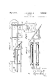
- Fig. 1 is a top plan view of the improved sub-grader Fig. 2 is a front elevation thereof;
- Fig. 3 is a partial sectional view, showing the discharge conveyor
- Fig. 4 is a longitudinal sectional view through the complete machine
- Fig. 5 is a partial transverse sectional view showing a modification in the conveyor structure
- Fig. 6 is a front elevation showing a further modification.
- forms designated by the numeral 1 in the drawings are placed along opposite sides of the road surface to receive the paving material therebetween.
- the sub-grader machine is designed for operation over these forms 1 and to ide therealong behind the paving machine in order to prepare thesurface toreceive the paving material. 7
- the machine is provided with main side channels 2, one on each side thereof, each of which is in sections, as shown in Fig. l, and connected by the channel 3 which is disposed beneath the channel sections 2 and is secured thereto;
- the side sections 2 are mounted on front and rear supporting wheels 4 and 5 respectively. These wheels f and 5 are adapted to ride upon the forms 1 to support the machine thereon, as shown particularly in Figs. 1 and 2.
- the channel 7 carries a plurality of scarifying teeth 8 which are suspended therefrom by suitable clamps which will permit adjustment of these teeth.
- Angle bars 9 are arranged at an acute angle to these channels 6 and 7 and secured therebetween to support cutting blades 10 which are suspended ther from and are supported by bolts 11 shown in Fig. l, which bolts extend through slots 12 in the angle bars 9 to permit adjustment of the plates 10.
- an intermediate channel 13 Arranged between the connecting side channels 3 are an intermediate channel 13, shown in Fig. l, and an angle bar 14, between which are carried transversely extending supporting plates 15, and the angle bar 14 also supports a transverse guide plate 16, whichcarri-es tester blades 17, the latter being adjusted by bolts 18, which are received in slots 19 in the guide plate 16.
- the guide plate 16 overlaps the upper plate 15 and is spaced vertically therefrom.
- a belt conveyer 20 has its upper and lower runs supported on the upper and lower plates 15 and extends over pulleys 21 at its opposite ends.
- the pulleys 21 are mounted on shaft 22 journaled'in guides 23 supported by the side chan-
- a scraper conveyor may be used instead of the belt conveyor 20.
- an independent source of power such as a small gasoline engine or the like, may be used or it may be driven from the rear wheels 5, shown in Fig. 1.
- a drive shaft 24 is fixed to the wheels 5 and is connected by spur-gearing 25 with a driven shaft 26.
- the shaft 26 is in turn connected with the shafts 22 by bevel gearing 27. Provision may be made in the driving gears for reversing the direction of rotation of the conveyor if found desirable.
- the machine is preferably drawn by the paving machine, which moves forward between the forms 1 and on such forward movement, the scarifying teeth 8 plow up the excess earthy material between the'forms 1,
- the cutting blades 10 act as cutters in the further removal of the excess earthy material.
- Theangular position of these cutting blades 10 also assists in moving excessive dirt into depressions that may have been left by form,- er grading operations. This brings the excess earthy material to a point where it has been furrowed up more .or less evenly with the grade line parallel with the form lines, and is the first attempt in the removal of excess earthy material and the filling of any depressions that may have been left in the grade during former grading operations.
- the excess dirt contacts with the tester blades 17, which are designed to be adjusted as desired, and these tester blades meet the incoming excess dirt and more or less evenly distribute the same over the total length of the several tester blades.
- the excess dirt is now in a position, as the machine moves forward, to effect the second or final filling of any depressions in the desired grade.
- each tester blade 17 has slots 30 therein to receive bolts 31 for adjusting the same.
- a wedge 32 has diagonal slots 33 therein in whlch bolts 34 are received, which when loosened permit the wedge 32 to slide upwardly or downwardly and hold the tester blade 1n place. When the wedge is set, it prevents the possibility of the tester blade being forced up to cause uneven scraping of the roadbed.
- the sub-grader may be operated in front of the paving machine instead of behind it.
- a sub-grader comprising a supporting frame, scarifying teeth carried thereby at the forward portion thereof, diagonally arranged scraper blades carried by the frame at the forward portion thereof and behind the scarifying teeth, a conveyor extending transversely across the frame, and a plurality of inclined tester blades arranged between the scraper blades and the conveyor and scraping material to fill depressions and dlrecting excess material upward onto the conveyor.
- a sub-grader comprising a supportmg frame, wheels for supporting the frame and adapted to ride on road forms, scarifying teeth carried at the front end of the frame, a plurality of diagonally arranged scraper blades suspended from the frame at the forward portion thereof behind the scarifylng teeth, a conveyor extending transversely across the frame for directing excess material therefrom, and a plurality of inclined tester blades arranged between the scraper blades and the conveyor and serving the dual purpose of scraping material to fill depressions in the road surface and to direct excess material onto the conveyor.
- a sub-grader comprising a supportlng frame, wheels for supporting the frame and adapted to ride on road forms, scarifylng teeth carried at the front end of the frame, a plurality of diagonally arranged scraper blades suspended from the frame at the forward portion thereof behind the scarlfying teeth, a conveyor extending transversely across the frame for directing excess material therefrom, a plurality of inclined tester blades arranged between the scraper blades and the conveyor and serving the dual purpose of scraping material to fill depressions in the road surface and to direct excess material onto the conveyor, and means operatively connecting the conveyor with the supporting wheels of the machine to drive the conveyor therefrom.
- a sub-grader comprising a supporting frame, including longitudinal and transverse supporting bars, wheels connected with the longitudinal bars and adapted to ride on road forms to support the machine thereon, diagonally arranged scraper blades carried by the transverse bars, means for adjusting the positions of said scraper blades, a conveyor extending transversely of the frame from side to side thereof for directing excess material from the machine, an inclined guiding plate carried by one of the transverse bars and having at least a portion thereof'overlapping the conveyor, one or more inclined tester blades carried by the guide plate and extending forwardly toward the scraping blades, means for adjustably connecting the tester blades with the inclined plate, said tester blades serving the dual function of scraping material to fill'depressions in the road surface and directing excess material onto the conveyor.
- a sub-grader comprising a, supporting frame, including longitudinaland transverse supporting bars, wheels connected with the longitudinal-bars and adapted to ride on road forms to support the machine thereon,
- a sub-grader comprising a supporting frame, an endless belt carried thereby and extending transversely of the sub-grader, a guide plate arranged at the forward side of said endless belt and overlapping said belt, and one or more tester blades adjustably connected with said guide plate and extending downwardly therefrom.
- a sub-grader comprising a supporting frame, an endless belt carried thereby and extending transversely of the sub-grader, a guide plate arranged at the forward end of the endless belt and overlapping the same, a
- a sub-grader comprising a supporting frame, an endless belt carried thereby and extending transversely of the sub-grader, a
- a sub-grader comprising a supporting frame, an endless belt carried thereby and extending transversely of the sub-grader, a guide plate arranged at the forward side of said endless belt and overlapping said belt,
- one or more tester blades adjustably connected with said guide plate and extending downwardly therefrom, and a locking wedge bearing against each tester blade to prevent y In testimony whereof I have signed my name, this 14th day of February. in the year one thousand nine hundred and thirty-one.
Landscapes
- Engineering & Computer Science (AREA)
- Mechanical Engineering (AREA)
- Mining & Mineral Resources (AREA)
- Civil Engineering (AREA)
- General Engineering & Computer Science (AREA)
- Structural Engineering (AREA)
- Road Repair (AREA)
Description
May 9, 1933. J, E. HARVEY, JR 1,908,348
SUBGRADER Filed March 17, 1931 2 Sheets-Sheet l ry a IN VEN TOR.
A TTORNEYS.
May 9, 1933. J, E. HARVEY, JR
SUBGRADER 2 Sheets-Sheet 2 Filed March l Patented May 9, 1933 UNITED STATES PATENT GFFEfiE JACQUELIN E. HARVEY, JR., OF JELLIGO, TENNESSEE, ASSIGNOR, BY MESNE ASSIGN- MENTS, TO CYRUS KEI-IR, OF WASHINGTON, DISTRICT OF COLUMBIA SUBGRADER Application filed March 17, 1931.
This invention relates to an improvement in sub-graders.
This machine, a sub-grader, is intended to furnish a finished grade prior to the laying of highway or road pavement. The present practice in the making of a sub-grade is the usage of the conventional sub-grader, which machine operates'on the grade as left by the rough grade machine, and proposes to bring the grade to the specified elevations by cutting away the excess soil or earthy material which is not needed to complete the final grade'elevations as specified by the various highway departments, usually in the shape of 7 a parabolic curve.
The grade as completed by the sub-grader heretofore used is by no means a finished grade, for many State highway commissions demand a sub-grade planer drawn by and behind the paving machine. The purpose of the sub-grade planer is the finishing of a grade which will conform absolutely to specifications. The fact that the usage of a subgrade planer is demanded by so many State highway commissions is in itself sufficient proof that the conventional sub-grader is en tirely inadequate for the completion of a final grade. The conventional sub-grade planer proposes to cut away, by means of cutting blades which are elevated to about fifteen degrees from the horizontal, the excess soil or earthy material, the removal of which, brings the grade to proper specifications.
The present grade machine proposes the consolidating of the work now accomplished I by the present sub-graders and sub-grade planers. This grader will be drawn by and behind the paving machine and can be designed to bring to grade specifications a grade that is as much as four or five inches high.
The invention embodiesthe following improved features in a sub-grade machine:
Frst.-A fine grade machine, including a wheeled frame adapted to be supported on rails disposed on opposite sides of the area to be graded, said machine to be placed back of, and may be drawn by, the paving mixer. This placing of the machine back of the paving mixer has the advantage of leaving the Serial No. 523,351.
area between the side forms open for free operation of hauling units, which of necessity operate within this area. Furthermore, it permits uninterrupted sprinkling and compacting operations between the rough grade operations and the paving unit. words, the placing of the sub-grader back of the paver materially speeds up the operat1on, an important consideration to the contractor.
Second-A sub-grade that will displace the necessary usage of a sub-grade machin ahead of the paving machine.
Third-A sub-grader that will cut away excess earthy material and deposit said material on a transverse conveyor belt without the assistance of moving elements other than the forward motion of the machine.
F0arth.-A sub-grader that will combine the work now performed by the conventional In other sub-grader and sub-grade planer, that is,
bringing the grade to the desired contour and testing this contour.
Fifth.A sub-grader that eliminates the necessity of its removal from the area within which it operates. The conventional type of grader heretofore used must be removed from the operated area in front of the paver because it blocks the passage of incoming and out-going trucks and other equipment.
Simth.-A sub-grader that will make two such manner as engineering practice distates.
Ninth.-A sub-grader that combines scarifiers, angular cutting or scraping blades, profile tester blades, and means for discharging excess material.
In the accompanying drawings:
' n-els of the machine.
Fig. 1 is a top plan view of the improved sub-grader Fig. 2 is a front elevation thereof;
Fig. 3 is a partial sectional view, showing the discharge conveyor; 7
Fig. 4: is a longitudinal sectional view through the complete machine;
Fig. 5 is a partial transverse sectional view showing a modification in the conveyor structure; and
Fig. 6 is a front elevation showing a further modification.
In the preparation of road surface to receive paving material, forms designated by the numeral 1 in the drawings are placed along opposite sides of the road surface to receive the paving material therebetween. The sub-grader machine is designed for operation over these forms 1 and to ide therealong behind the paving machine in order to prepare thesurface toreceive the paving material. 7
The machine is provided with main side channels 2, one on each side thereof, each of which is in sections, as shown in Fig. l, and connected by the channel 3 which is disposed beneath the channel sections 2 and is secured thereto; The side sections 2 are mounted on front and rear supporting wheels 4 and 5 respectively. These wheels f and 5 are adapted to ride upon the forms 1 to support the machine thereon, as shown particularly in Figs. 1 and 2. Arranged between the side channels 2 and secured thereto, as by bolting, riveting, welding or the like, are parallel front channels 6 and 7. The channel 7 carries a plurality of scarifying teeth 8 which are suspended therefrom by suitable clamps which will permit adjustment of these teeth. Angle bars 9 are arranged at an acute angle to these channels 6 and 7 and secured therebetween to support cutting blades 10 which are suspended ther from and are supported by bolts 11 shown in Fig. l, which bolts extend through slots 12 in the angle bars 9 to permit adjustment of the plates 10. I
Arranged between the connecting side channels 3 are an intermediate channel 13, shown in Fig. l, and an angle bar 14, between which are carried transversely extending supporting plates 15, and the angle bar 14 also supports a transverse guide plate 16, whichcarri-es tester blades 17, the latter being adjusted by bolts 18, which are received in slots 19 in the guide plate 16. The guide plate 16 overlaps the upper plate 15 and is spaced vertically therefrom. A belt conveyer 20 has its upper and lower runs supported on the upper and lower plates 15 and extends over pulleys 21 at its opposite ends. The pulleys 21 are mounted on shaft 22 journaled'in guides 23 supported by the side chan- A scraper conveyor may be used instead of the belt conveyor 20.
For driving the belt conveyor 20 either an independent source of power, such as a small gasoline engine or the like, may be used or it may be driven from the rear wheels 5, shown in Fig. 1. A drive shaft 24 is fixed to the wheels 5 and is connected by spur-gearing 25 with a driven shaft 26. The shaft 26 is in turn connected with the shafts 22 by bevel gearing 27. Provision may be made in the driving gears for reversing the direction of rotation of the conveyor if found desirable.
The machine is preferably drawn by the paving machine, which moves forward between the forms 1 and on such forward movement, the scarifying teeth 8 plow up the excess earthy material between the'forms 1,
which it is desired to remove and level for v the completion of the specified grade. The cutting blades 10 act as cutters in the further removal of the excess earthy material. Theangular position of these cutting blades 10 also assists in moving excessive dirt into depressions that may have been left by form,- er grading operations. This brings the excess earthy material to a point where it has been furrowed up more .or less evenly with the grade line parallel with the form lines, and is the first attempt in the removal of excess earthy material and the filling of any depressions that may have been left in the grade during former grading operations. As the grader continues to move in a forward direction, the excess dirt contacts with the tester blades 17, which are designed to be adjusted as desired, and these tester blades meet the incoming excess dirt and more or less evenly distribute the same over the total length of the several tester blades. The excess dirt is now in a position, as the machine moves forward, to effect the second or final filling of any depressions in the desired grade. r
Should this excess material not be needed for filling purposes, it is pushed up the tester blades and guide plate 16 by the force of incoming excess material and the forward motion of the machine, and is deposited onto the conveyor belt 20, which is driven transversely of the machine and of the road bed to convey this excess material to one side of the grade and outside of the forms.
This serves to effectively prepare the road surface to receive the paving material and accomplishes the purpose-of both the presintermediate rollers 29, on which the upper and lower runs of the belt conveyor20 run. and which rollers 29 support the belt con veyor intermediate its ends. This reduces the friction acting on the belt conveyor and effectively supports the same intermediate its ends.
in the form shown in Fig. 6, each tester blade 17 has slots 30 therein to receive bolts 31 for adjusting the same. A wedge 32 has diagonal slots 33 therein in whlch bolts 34 are received, which when loosened permit the wedge 32 to slide upwardly or downwardly and hold the tester blade 1n place. When the wedge is set, it prevents the possibility of the tester blade being forced up to cause uneven scraping of the roadbed.
If desired, the sub-grader may be operated in front of the paving machine instead of behind it.
I claim:
1. A sub-grader comprising a supporting frame, scarifying teeth carried thereby at the forward portion thereof, diagonally arranged scraper blades carried by the frame at the forward portion thereof and behind the scarifying teeth, a conveyor extending transversely across the frame, and a plurality of inclined tester blades arranged between the scraper blades and the conveyor and scraping material to fill depressions and dlrecting excess material upward onto the conveyor.
2. A sub-grader comprising a supportmg frame, wheels for supporting the frame and adapted to ride on road forms, scarifying teeth carried at the front end of the frame, a plurality of diagonally arranged scraper blades suspended from the frame at the forward portion thereof behind the scarifylng teeth, a conveyor extending transversely across the frame for directing excess material therefrom, and a plurality of inclined tester blades arranged between the scraper blades and the conveyor and serving the dual purpose of scraping material to fill depressions in the road surface and to direct excess material onto the conveyor.
3. A sub-grader comprising a supportlng frame, wheels for supporting the frame and adapted to ride on road forms, scarifylng teeth carried at the front end of the frame, a plurality of diagonally arranged scraper blades suspended from the frame at the forward portion thereof behind the scarlfying teeth, a conveyor extending transversely across the frame for directing excess material therefrom, a plurality of inclined tester blades arranged between the scraper blades and the conveyor and serving the dual purpose of scraping material to fill depressions in the road surface and to direct excess material onto the conveyor, and means operatively connecting the conveyor with the supporting wheels of the machine to drive the conveyor therefrom.
A sub-grader comprising a supporting frame, including longitudinal and transverse supporting bars, wheels connected with the longitudinal bars and adapted to ride on road forms to support the machine thereon, diagonally arranged scraper blades carried by the transverse bars, means for adjusting the positions of said scraper blades, a conveyor extending transversely of the frame from side to side thereof for directing excess material from the machine, an inclined guiding plate carried by one of the transverse bars and having at least a portion thereof'overlapping the conveyor, one or more inclined tester blades carried by the guide plate and extending forwardly toward the scraping blades, means for adjustably connecting the tester blades with the inclined plate, said tester blades serving the dual function of scraping material to fill'depressions in the road surface and directing excess material onto the conveyor.
5. A sub-grader comprising a, supporting frame, including longitudinaland transverse supporting bars, wheels connected with the longitudinal-bars and adapted to ride on road forms to support the machine thereon,
diagonally arranged scraper blades carried by the transverse bars, means for adjusting the positions of said scraper blades, a conveyor extending transversely of the frame from side to side thereof for directing excess material from the machine, an inclined guiding plate carried by one of the transverse bars and having at least a portion thereof overlapping the conveyor, one or more inclined tester blades carried by the guide plate and extending forwardly toward the scraping blades, means for adjustably connecting the tester blades with the inclined plate, said tester blades serving the dual function of scraping material to fill depressions in the road surfacev and directing excess material onto the conveyor, the movement of the material up the inclined blades and plate being caused solely by the force of the forward motion of the machine, and means for 0per-- atively connecting the conveyor with the wheels of the machine to drive the conveyor therefrom.
6. A sub-grader comprising a supporting frame, an endless belt carried thereby and extending transversely of the sub-grader, a guide plate arranged at the forward side of said endless belt and overlapping said belt, and one or more tester blades adjustably connected with said guide plate and extending downwardly therefrom.
7. A sub-grader comprising a supporting frame, an endless belt carried thereby and extending transversely of the sub-grader, a guide plate arranged at the forward end of the endless belt and overlapping the same, a
plurality of tester blades connected with the lower edge of said guide plate and extending downwardly therefrom, and slot and bolt connecting means between the guide plate and tester blades for adjusting said blades relative to the guide plate.
8. A sub-grader comprising a supporting frame, an endless belt carried thereby and extending transversely of the sub-grader, a
guide plate arranged at the forward side of saidendless belt and overlapping said belt. and one or more tester blades adjustably con-- nected with said guide plate and extending downwardly therefrom, a locking wedge bearing against the upper edges of the tester blades, and having inclined slots therein, and bolts connected with the guide plate and v1 entering said slots to regulate the adjust- .ment of the wedge and tester plates.
9. A sub-grader comprising a supporting frame, an endless belt carried thereby and extending transversely of the sub-grader, a guide plate arranged at the forward side of said endless belt and overlapping said belt,
displacement thereof.
one or more tester blades adjustably connected with said guide plate and extending downwardly therefrom, and a locking wedge bearing against each tester blade to prevent y In testimony whereof I have signed my name, this 14th day of February. in the year one thousand nine hundred and thirty-one.
JACQUELIN E. HARVEY, JR.
Priority Applications (1)
| Application Number | Priority Date | Filing Date | Title |
|---|---|---|---|
| US523351A US1908348A (en) | 1931-03-17 | 1931-03-17 | Subgrader |
Applications Claiming Priority (1)
| Application Number | Priority Date | Filing Date | Title |
|---|---|---|---|
| US523351A US1908348A (en) | 1931-03-17 | 1931-03-17 | Subgrader |
Publications (1)
| Publication Number | Publication Date |
|---|---|
| US1908348A true US1908348A (en) | 1933-05-09 |
Family
ID=24084657
Family Applications (1)
| Application Number | Title | Priority Date | Filing Date |
|---|---|---|---|
| US523351A Expired - Lifetime US1908348A (en) | 1931-03-17 | 1931-03-17 | Subgrader |
Country Status (1)
| Country | Link |
|---|---|
| US (1) | US1908348A (en) |
-
1931
- 1931-03-17 US US523351A patent/US1908348A/en not_active Expired - Lifetime
Similar Documents
| Publication | Publication Date | Title |
|---|---|---|
| US4186968A (en) | Roadway pavement planing machine | |
| US2065698A (en) | Stone spreading machine | |
| US3560050A (en) | Machines for removing worn road surfaces | |
| US1858327A (en) | Channeling machine | |
| US4971476A (en) | Road retreatment plant | |
| US2109020A (en) | Road paver | |
| GB2074218A (en) | Track renewal machine comprising a ballast bed clearing and levelling unit | |
| US1750896A (en) | Subgrade planer and concrete-distributing machine | |
| US2054436A (en) | Apparatus for building roads | |
| US1908348A (en) | Subgrader | |
| US20030143024A1 (en) | Method and apparatus for laying roadway materials | |
| US1979619A (en) | Road building machine | |
| US2957254A (en) | Subgrade planer | |
| US1849754A (en) | Subgrading attachment for power graders | |
| US2159509A (en) | Apparatus for building roads | |
| US1817161A (en) | Machine for spreading and surfacing construction material | |
| US1807489A (en) | Ditch-filling machine | |
| DE943530C (en) | Trench fillers for excavation deposited on both sides of the trench | |
| US2068702A (en) | Pavement constructing | |
| DE886287C (en) | Schraemmaschine | |
| US1945517A (en) | Road grader | |
| US1956931A (en) | Machine for fine grading | |
| US1926397A (en) | Precision apparatus for cutting roads to final grade | |
| US1653333A (en) | Fine-grading machine for highway construction | |
| US1994082A (en) | Road spreader |