US1908347A - Electric distant recording apparatus - Google Patents
Electric distant recording apparatus Download PDFInfo
- Publication number
- US1908347A US1908347A US536241A US53624131A US1908347A US 1908347 A US1908347 A US 1908347A US 536241 A US536241 A US 536241A US 53624131 A US53624131 A US 53624131A US 1908347 A US1908347 A US 1908347A
- Authority
- US
- United States
- Prior art keywords
- recording
- drum
- movement
- contact
- contacts
- Prior art date
- Legal status (The legal status is an assumption and is not a legal conclusion. Google has not performed a legal analysis and makes no representation as to the accuracy of the status listed.)
- Expired - Lifetime
Links
Images


Classifications
-
- G—PHYSICS
- G08—SIGNALLING
- G08C—TRANSMISSION SYSTEMS FOR MEASURED VALUES, CONTROL OR SIMILAR SIGNALS
- G08C19/00—Electric signal transmission systems
- G08C19/02—Electric signal transmission systems in which the signal transmitted is magnitude of current or voltage
Definitions
- ity such as the movements of the regulator or the reversing lever of a locomotive or the recording of grades and slopes and superelevation on curves.
- the object of the present invention is to adapt recording apparatus of the kind referred to for use incases where the movements of the external phenomena under observation are of an oscillatory or reciprocatory character, and to produce a continuous graph which will show the amplitude of the oscillation or reciprocation at any instant, and the manner in which it varies.
- the invention involves the use, in combination with duplicated recording apparatus of the kind referred to of means whereby the oscillatory or reciprocatory movement under observation is communicated to a pair of contacts in such a manner that one half of each oscillation or reciprocation causes one of the contacts to move to a corresponding extent along its associated resistance whilst the other half of each oscillation causes the other contact to move to a corresponding extent along its associated resistance.
- These two resistances are each connected in parallel with a corresponding resistance on the recording side of the apparatus and the two contacts are each electrically connected through the winding of a relay with a corresponding recording contact which is in each case adapted to be moved along its resistance through the operation of a contactor and an electric motor having an oscillating armature, to restore equality of potential and at the same time to cause a recording pen to describe a graph of its movements upon a traveling sheet of paper.
- the simultaneously recorded graphs of the two pens enclose an area the cross-sectional dimension of which at any point is a measure of the maximum relative movement at any moment between the parts under 0bservation.
- the present invention also includes the provision of means for recording the frequency of the oscillations or reciprocations at any instant of the external phenomena under observation, in addition to the recording of the amplitude thereof.
- Figures 1 and 2 are front and side views respectively of the duplicated recording instrument.
- Figures 3 and 4 are similar views of the transmitter.
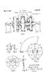
- Figure 5 is a view partly in section of the spring drum assembly.
- Figure 6 is a side view of the central drum.
- FIGS 7 and 8 and 9 and 10 are detail views of the bearing covers for the spring drum assembly.
- Figure 11 is a wiring diagram of the duplex apparatus.
- Figure 12 a plan of a graph showing the position of the zero and recording pens.
- Figure 13 a construction for operating a dynamo from the member a for the purposes of supplying an alternating current to a frequency meter which will record the frequency or periodicity of the oscillations or reciprocations simultaneously with the amplitude recorded by the pens f, 7.
- a, (1 represent the arms of the recording contacts which are each adapted to be moved over their respective resistances I), b by the motors 0, 0.
- the motors are controlle by relays d, d through contactors e, e.
- the arms of the recording contacts are severally connected with two recording pens f, arranged to move in contact with a traveling sheet of paper.
- a pair of zero pens h, h are also provided as shown in Figure 2.
- the record sheet on which the graphs are traced by the pens f, f and h, h is fed from a roll 11 over a plate k, round a driving roller Z to the receiving roll 2.
- the two contacts a, a which are directly affected by the phenomena under observation, are each carried by a rotatable spring drum m, m, and these two contact operating drums are actuated by a central rotatable spring drum n arranged co-axially therewith.
- This portion of the apparatus i. e. the transmitter, is mounted upon one of the two parts whose relative movements it is desired to record, the other part being connected by means of a Bowden wire, cable or the like flexible connection 0 with the central drum which for this purpose is provided with a peripherally grooved sector-shaped plate 71
- the bearing cover plates a fixed to each side of the central drum are provided with segmental projections n having bevelled ends.
- the projections are adapted to abut against corresponding projections 122 m on the adjacent faces of plates of, m carried by the contact operating drums m, 121.
- These plates are free to yield axially against springs m m so as to enable the projections 11 on the central drum to overrun the projections on the drums m, m in cases where the relative movement between the observed parts exceeds a predetermined amount.
- the arrangement is such that when relative movement of the parts under observation takes place in one direction, the central drum n is turned about its axis against its spring by amounts strictly proportional to the relative movement at that instant and imparts a corresponding angular movement to one of the contact operating drums m, m. This causes the associated contact a to move to a like extent along its resistance 6 thereby causing a similar or proportionate movement a Similarly, when relative movement between the observed parts takes place in the return or opposite direction, the central drum n causes a corresponding angular movement of the other contact operating drum with resulting movement of its associated contact a along its resistance 7), thereby causing a similar or proportionate movement of the corresponding recording contact a and pen f.
- the contact operating drums After each such movement the contact operating drums return toward their neutral positions under the influence of their respective springs and at a speed which is regulated by means of a dash-pot device p, so as to be in a position to receive the next forward movement from the central drum.
- the said return speed is so adjusted as to enable the instrument to transmit to the recording instrument relative oscillatory or reciprocatory movements which may vary rapidly both in speed and amplitude.
- the zero graphs which are produced by the pens h eliminate any inaccuracies that might otherwise appear on the record sheet due. for instance, to the feeding mechanism of the latter and removes the necessity for very exact registration which would be required if the sheet had a zero line printed on it.
- advantage may be taken of the oscillatory movement of the central drum n to set up electric currents in one or the other direction according to the direction of oscillation of the drum, said currents being used to actuate a frequency recording device of any approved type.
- the oscillatory movement of the drum n is imparted to an electrical mechanism so designed that an alternating current is produced of exactly the same frequency of that of the movement it is desired to record.
- This alternating current operates a recording frequency meter of any approved design which will therefore record a graph representing the frequency of the observed relative movement at any instant.
- Figure 13 shows one embodiment of this feature and illustrates the adaptation of the transmitter shown in Figures 3 and 4 for the purpose intended.
- the plate n is formed with gear teeth and arranged to mesh with a pinion fixed to the spindle of the armature of a small dynamo.
- the armature is caused to turn nection with one of the two first in one direction and then in the other.
- an electrical impulse will be generated first in one sense and then in the other alternately, the resulting effect being the generation of an alternating current of a frequency that corresponds exactly to that of the movement under observation at any instant.
- the frequency recording device will produce a continuous graph showing the frequency of the oscillations or reciprocations under observation at any instant and this graph may conveniently be produced upon the same sheet on which the amplitude of the oscillations or reciprocations are record-
- the improved apparatus as will be understood, is capable of application to a variety of different uses and, in particular, for recording the oscillatory movements of rolling stock.
- a pair of rotatable spring drums each carrying one of the two transmitting contacts of said apparatus and means associated with the parts whose relative oscillatory or reciprocatory movement it is desired to record whereby one half of each oscillation or reciprocation is communicated to one drum and the other half to the other drum.
- a-pair of co-axially arranged rotatable spring drums each carrying one of the two transmittin contacts of said apparatus a third rotata 1e spring drum adapted for connection with one of the two parts the frequency and amplitude of whose relative oscillatory or reciprocatory movements it is desired to record, said third drum being aranged between and co-axially with the two contact-carrying drums so that one half of each oscillation or reciprocation is communicated to one contact and the other half to the other contact, a frequency recording device, a fixed armature associated with said third drum and having its terminals connected with said frequency device and pole pieces adapted to oscillate with said drum about said armature.
- a pair of recording pens independent means for moving each said pen, a pair of movable contacts mounted on an element, electrical means controlled by the respective contacts for causing independent movement of said pens, in combination with an oscillatory control member mounted on said element, and means connected to said member and to an additional element whereby relative movement between said elements will cause an oscillatory movement of said control member.
- a pair of recording pens independent means for moving each said pen, a pair of movable contacts mounted on an element, electrical means controlled by the respective contacts for causing independent movement of said pens, in combination with an oscillatory control member mounted on said element, means connected to said member and to an additional element whereby relative movement be. tween said elements will cause an oscillatory movement of said control member, and electrical means for recording the frequency of the oscillations of said control member.
Landscapes
- Physics & Mathematics (AREA)
- General Physics & Mathematics (AREA)
Description
May 9; 1933. s. J. HARLEY ELECTRIC DISTANT RECORDING AP PARATUS 4 Sheets-Sheet 1 Filed May 9, 1931 INVENTOR:
May 9, 1933. s. J. HARLEY ELECTRIC DISTANT RECORDING APPARATUS Filed May 9, 1931 4 Sheets-Sheet 2 INVENTOR W May 9, 1933. s. J. HARLEY ELECTRIC DISTANT RECORDING APPARATUS Filed May 9, 1951 4 Sheets-Sheet 3 May 9, 1933. s. J. HARLEY ELECTRIC DISTANT RECORDING APPARATUS Filed May 9, 1931 4, Sheets-Sheet 4 INVENTOR Patented May 9, 1933 PATENT OFFICE STANLEY JAFFA HARLEY, 0F COVENTRY, ENGLAND ELECTRIC DISTANT RECORDING APPARATUS Application filed May 9, 1931, Serial No. 536,241, and in Great Britain May 29, 1930.
For the distant recording of the movements of external phenomena it has already been proposed to employ electric apparatus operating on the principle of the Wheatstone bridge and comprising two contacts severally operating in conjunction with two resistances connected at opposite ends of the bridge wire across supply mains, one of said contacts carrying a recording pen and the other being connected with the part the movement of which it is desired to record. The arrangement is such that when relative movement takes place between the transmitting contact and its associated resistance it disturbs the balance of current in the bridge wire and produces a corresponding or proportional relative movement between the recording contact and its associated resistance.
Owing to a short but unavoidable period of lag between the transmitting and recording elements the use of this type of apparatus in its simple form with a single transmitting instrument and a single recording instrument is limited to the recording of movements having relatively low periodic-.
ity, such as the movements of the regulator or the reversing lever of a locomotive or the recording of grades and slopes and superelevation on curves.
For this reason the said apparatus in its simple form aforesaid cannot be successfully employed to deal with such rapid movements as spring oscillations as where, for example, it is desired to record the relative movements between the undercarriage and bogey frame of a railway coach, or relative movements between neighboring vehicles and a dynamometer car carrying the recording elements. 7
The object of the present invention is to adapt recording apparatus of the kind referred to for use incases where the movements of the external phenomena under observation are of an oscillatory or reciprocatory character, and to produce a continuous graph which will show the amplitude of the oscillation or reciprocation at any instant, and the manner in which it varies.
The invention involves the use, in combination with duplicated recording apparatus of the kind referred to of means whereby the oscillatory or reciprocatory movement under observation is communicated to a pair of contacts in such a manner that one half of each oscillation or reciprocation causes one of the contacts to move to a corresponding extent along its associated resistance whilst the other half of each oscillation causes the other contact to move to a corresponding extent along its associated resistance.
These two resistances are each connected in parallel with a corresponding resistance on the recording side of the apparatus and the two contacts are each electrically connected through the winding of a relay with a corresponding recording contact which is in each case adapted to be moved along its resistance through the operation of a contactor and an electric motor having an oscillating armature, to restore equality of potential and at the same time to cause a recording pen to describe a graph of its movements upon a traveling sheet of paper.
The simultaneously recorded graphs of the two pens enclose an area the cross-sectional dimension of which at any point is a measure of the maximum relative movement at any moment between the parts under 0bservation.
The present invention also includes the provision of means for recording the frequency of the oscillations or reciprocations at any instant of the external phenomena under observation, in addition to the recording of the amplitude thereof.
In the accompanying drawings,
Figures 1 and 2 are front and side views respectively of the duplicated recording instrument.
Figures 3 and 4: are similar views of the transmitter.
Figure 5 is a view partly in section of the spring drum assembly.
Figure 6 is a side view of the central drum.
Figures 7 and 8 and 9 and 10 are detail views of the bearing covers for the spring drum assembly.
Figure 11 is a wiring diagram of the duplex apparatus.
Figure 12, a plan of a graph showing the position of the zero and recording pens.
Figure 13, a construction for operating a dynamo from the member a for the purposes of supplying an alternating current to a frequency meter which will record the frequency or periodicity of the oscillations or reciprocations simultaneously with the amplitude recorded by the pens f, 7.
Referring to Figures 1 and 2, which show the duplicated recording instrument, a, (1 represent the arms of the recording contacts which are each adapted to be moved over their respective resistances I), b by the motors 0, 0. The motors are controlle by relays d, d through contactors e, e. The arms of the recording contacts are severally connected with two recording pens f, arranged to move in contact with a traveling sheet of paper. A pair of zero pens h, h are also provided as shown in Figure 2. The record sheet on which the graphs are traced by the pens f, f and h, h is fed from a roll 11 over a plate k, round a driving roller Z to the receiving roll 2.
In the transmitting instrument, shown in Figures 3 and 4, the two contacts a, a which are directly affected by the phenomena under observation, are each carried by a rotatable spring drum m, m, and these two contact operating drums are actuated by a central rotatable spring drum n arranged co-axially therewith.
This portion of the apparatus, i. e. the transmitter, is mounted upon one of the two parts whose relative movements it is desired to record, the other part being connected by means of a Bowden wire, cable or the like flexible connection 0 with the central drum which for this purpose is provided with a peripherally grooved sector-shaped plate 71 The bearing cover plates a fixed to each side of the central drum are provided with segmental projections n having bevelled ends. The projections are adapted to abut against corresponding projections 122 m on the adjacent faces of plates of, m carried by the contact operating drums m, 121. These plates are free to yield axially against springs m m so as to enable the projections 11 on the central drum to overrun the projections on the drums m, m in cases where the relative movement between the observed parts exceeds a predetermined amount.
The arrangement is such that when relative movement of the parts under observation takes place in one direction, the central drum n is turned about its axis against its spring by amounts strictly proportional to the relative movement at that instant and imparts a corresponding angular movement to one of the contact operating drums m, m. This causes the associated contact a to move to a like extent along its resistance 6 thereby causing a similar or proportionate movement a Similarly, when relative movement between the observed parts takes place in the return or opposite direction, the central drum n causes a corresponding angular movement of the other contact operating drum with resulting movement of its associated contact a along its resistance 7), thereby causing a similar or proportionate movement of the corresponding recording contact a and pen f. After each such movement the contact operating drums return toward their neutral positions under the influence of their respective springs and at a speed which is regulated by means of a dash-pot device p, so as to be in a position to receive the next forward movement from the central drum. The said return speed is so adjusted as to enable the instrument to transmit to the recording instrument relative oscillatory or reciprocatory movements which may vary rapidly both in speed and amplitude.
With this arrangement the graph produced by the recording pens f will be similar to that shown in Figure 12 and will represent the two extremes of the relative movement and show its amplitude at any instant.
The zero graphs which are produced by the pens h eliminate any inaccuracies that might otherwise appear on the record sheet due. for instance, to the feeding mechanism of the latter and removes the necessity for very exact registration which would be required if the sheet had a zero line printed on it.
Where it is desired to obtain a simultaneous record in graphic form of the frequency of the oscillations or reciprocations, in addition to the amplitude thereof, advantage may be taken of the oscillatory movement of the central drum n to set up electric currents in one or the other direction according to the direction of oscillation of the drum, said currents being used to actuate a frequency recording device of any approved type.
For this purpose the oscillatory movement of the drum n is imparted to an electrical mechanism so designed that an alternating current is produced of exactly the same frequency of that of the movement it is desired to record. This alternating current operates a recording frequency meter of any approved design which will therefore record a graph representing the frequency of the observed relative movement at any instant. Figure 13 shows one embodiment of this feature and illustrates the adaptation of the transmitter shown in Figures 3 and 4 for the purpose intended. The plate n is formed with gear teeth and arranged to mesh with a pinion fixed to the spindle of the armature of a small dynamo. As the drum n oscillates about its axis the armature is caused to turn nection with one of the two first in one direction and then in the other. Thus an electrical impulse will be generated first in one sense and then in the other alternately, the resulting effect being the generation of an alternating current of a frequency that corresponds exactly to that of the movement under observation at any instant.
The frequency recording device will produce a continuous graph showing the frequency of the oscillations or reciprocations under observation at any instant and this graph may conveniently be produced upon the same sheet on which the amplitude of the oscillations or reciprocations are record- The improved apparatus, as will be understood, is capable of application to a variety of different uses and, in particular, for recording the oscillatory movements of rolling stock.
I claim,
1. In electric distant recording apparatus of the character described arranged in duplicate, a pair of rotatable spring drums each carrying one of the two transmitting contacts of said apparatus and means associated with the parts whose relative oscillatory or reciprocatory movement it is desired to record whereby one half of each oscillation or reciprocation is communicated to one drum and the other half to the other drum.
2. In electric distant recording apparatus of the character described arranged in duplicate, a pair of coaxially arranged rotatable spring drums each carrying one of the two transmittin contacts of said apparatus, and a third rotatable spring drum adapted for connection with one of the two parts the amplitude of whose relative oscillatory or reciprocatory movements it is desired to record said third drum being arranged between and coaxially with the two contact-carrying drums so that one half of each oscillation or reciprocation is communicated to one contact and the other half to the other contact.
3. In electric distant recording apparatus of the character described arranged in duplicate, a pair of co-axially arranged rotatable spring drums each carrying one of the two transmittin contacts of said apparatus, a third rotata le spring drum adapted for conparts the frequency and amplitude of whose relative oscillatory or reciprocatory movements it is desired to record, said third drum being arranged between and co-axially with the two contact-carrying drums so that one half of each oscillation or reciprocation is communicated to one contact and the other half to the other contact, means associated with said third drum whereby/the oscillatory movement thereof is caused to generate electric currents in opposite directions and a frequencyrecording device adapted for operation by said currents;
4. In electric distant recording apparatus of the character described arranged in duplicate, a-pair of co-axially arranged rotatable spring drums each carrying one of the two transmittin contacts of said apparatus a third rotata 1e spring drum adapted for connection with one of the two parts the frequency and amplitude of whose relative oscillatory or reciprocatory movements it is desired to record, said third drum being aranged between and co-axially with the two contact-carrying drums so that one half of each oscillation or reciprocation is communicated to one contact and the other half to the other contact, a frequency recording device, a fixed armature associated with said third drum and having its terminals connected with said frequency device and pole pieces adapted to oscillate with said drum about said armature.
5. In electric distant recording apparatus, a pair of recording pens, independent means for moving each said pen, a pair of movable contacts mounted on an element, electrical means controlled by the respective contacts for causing independent movement of said pens, in combination with an oscillatory control member mounted on said element, and means connected to said member and to an additional element whereby relative movement between said elements will cause an oscillatory movement of said control member.
6. In electric distant recording apar'atus, a pair of recording pens, independent means for moving each said pen, a pair of movable contacts mounted on an element, electrical means controlled by the respective contacts for causing independent movement of said pens, in combination with an oscillatory control member mounted on said element, means connected to said member and to an additional element whereby relative movement be. tween said elements will cause an oscillatory movement of said control member, and electrical means for recording the frequency of the oscillations of said control member.
In testimony whereof, I have signed my name to this specification at Coventry,'England this 11th day of February 1931.
STANLEY JAFFA HARLEY.
Applications Claiming Priority (1)
| Application Number | Priority Date | Filing Date | Title |
|---|---|---|---|
| GB1908347X | 1930-05-29 |
Publications (1)
| Publication Number | Publication Date |
|---|---|
| US1908347A true US1908347A (en) | 1933-05-09 |
Family
ID=10893363
Family Applications (1)
| Application Number | Title | Priority Date | Filing Date |
|---|---|---|---|
| US536241A Expired - Lifetime US1908347A (en) | 1930-05-29 | 1931-05-09 | Electric distant recording apparatus |
Country Status (1)
| Country | Link |
|---|---|
| US (1) | US1908347A (en) |
Cited By (1)
| Publication number | Priority date | Publication date | Assignee | Title |
|---|---|---|---|---|
| US2512670A (en) * | 1948-02-06 | 1950-06-27 | Elwood H Mullins | Recording inclinometer |
-
1931
- 1931-05-09 US US536241A patent/US1908347A/en not_active Expired - Lifetime
Cited By (1)
| Publication number | Priority date | Publication date | Assignee | Title |
|---|---|---|---|---|
| US2512670A (en) * | 1948-02-06 | 1950-06-27 | Elwood H Mullins | Recording inclinometer |
Similar Documents
| Publication | Publication Date | Title |
|---|---|---|
| US1665857A (en) | Electrical transmission system | |
| US1908347A (en) | Electric distant recording apparatus | |
| US1086729A (en) | Electrical control apparatus. | |
| US1685965A (en) | Magnetic testing apparatus and method of testing | |
| US1749842A (en) | Electromagnetic controlling apparatus | |
| US925180A (en) | Method of and apparatus for measuring power. | |
| US1712113A (en) | Method, apparatus, and symbols for recording and indicating sound waves | |
| US1669298A (en) | Rotary timing switch | |
| US1077596A (en) | Geographical-position indicator. | |
| US232253A (en) | Stephen d | |
| US2024845A (en) | Device for use in operating track relays in railway signaling systems | |
| US607997A (en) | Vehicle | |
| US2417287A (en) | Steering gear for trailers | |
| US2079751A (en) | Motor vehicle brake testing device | |
| USRE11780E (en) | krieger | |
| US1121382A (en) | Electrically-propelled vehicle. | |
| US2019313A (en) | Stress-strain control for recording instruments | |
| US490699A (en) | Recording-am meter | |
| US508614A (en) | Recorder of speed of driven shafts | |
| US354793A (en) | Electric motor for railways | |
| US1312596A (en) | Ginia | |
| US433402A (en) | Reversing-gear for electric cars | |
| US402311A (en) | Petetts | |
| US300828A (en) | adams | |
| US529300A (en) | o -neil |