US1908336A - Rectifying system - Google Patents
Rectifying system Download PDFInfo
- Publication number
- US1908336A US1908336A US263141A US26314128A US1908336A US 1908336 A US1908336 A US 1908336A US 263141 A US263141 A US 263141A US 26314128 A US26314128 A US 26314128A US 1908336 A US1908336 A US 1908336A
- Authority
- US
- United States
- Prior art keywords
- rectifier
- current
- voltage
- inductance
- electrode means
- Prior art date
- Legal status (The legal status is an assumption and is not a legal conclusion. Google has not performed a legal analysis and makes no representation as to the accuracy of the status listed.)
- Expired - Lifetime
Links
- VYPSYNLAJGMNEJ-UHFFFAOYSA-N Silicium dioxide Chemical compound O=[Si]=O VYPSYNLAJGMNEJ-UHFFFAOYSA-N 0.000 description 9
- 239000002253 acid Substances 0.000 description 7
- 239000007788 liquid Substances 0.000 description 7
- PXHVJJICTQNCMI-UHFFFAOYSA-N Nickel Chemical compound [Ni] PXHVJJICTQNCMI-UHFFFAOYSA-N 0.000 description 6
- 239000000463 material Substances 0.000 description 5
- 229910052751 metal Inorganic materials 0.000 description 5
- 239000002184 metal Substances 0.000 description 5
- 229910052709 silver Inorganic materials 0.000 description 5
- 239000004332 silver Substances 0.000 description 5
- 230000002745 absorbent Effects 0.000 description 4
- 239000002250 absorbent Substances 0.000 description 4
- 230000008859 change Effects 0.000 description 4
- 239000004020 conductor Substances 0.000 description 4
- 230000000694 effects Effects 0.000 description 4
- 239000000377 silicon dioxide Substances 0.000 description 4
- 229910052759 nickel Inorganic materials 0.000 description 3
- 238000004804 winding Methods 0.000 description 3
- XEEYBQQBJWHFJM-UHFFFAOYSA-N Iron Chemical compound [Fe] XEEYBQQBJWHFJM-UHFFFAOYSA-N 0.000 description 2
- XUIMIQQOPSSXEZ-UHFFFAOYSA-N Silicon Chemical compound [Si] XUIMIQQOPSSXEZ-UHFFFAOYSA-N 0.000 description 2
- 239000010425 asbestos Substances 0.000 description 2
- 239000000084 colloidal system Substances 0.000 description 2
- 150000001875 compounds Chemical class 0.000 description 2
- 239000011521 glass Substances 0.000 description 2
- 239000011491 glass wool Substances 0.000 description 2
- 230000001939 inductive effect Effects 0.000 description 2
- 239000000395 magnesium oxide Substances 0.000 description 2
- CPLXHLVBOLITMK-UHFFFAOYSA-N magnesium oxide Inorganic materials [Mg]=O CPLXHLVBOLITMK-UHFFFAOYSA-N 0.000 description 2
- AXZKOIWUVFPNLO-UHFFFAOYSA-N magnesium;oxygen(2-) Chemical compound [O-2].[Mg+2] AXZKOIWUVFPNLO-UHFFFAOYSA-N 0.000 description 2
- 239000004033 plastic Substances 0.000 description 2
- 229910052895 riebeckite Inorganic materials 0.000 description 2
- 229910052710 silicon Inorganic materials 0.000 description 2
- 239000010703 silicon Substances 0.000 description 2
- AOSZTAHDEDLTLQ-AZKQZHLXSA-N (1S,2S,4R,8S,9S,11S,12R,13S,19S)-6-[(3-chlorophenyl)methyl]-12,19-difluoro-11-hydroxy-8-(2-hydroxyacetyl)-9,13-dimethyl-6-azapentacyclo[10.8.0.02,9.04,8.013,18]icosa-14,17-dien-16-one Chemical compound C([C@@H]1C[C@H]2[C@H]3[C@]([C@]4(C=CC(=O)C=C4[C@@H](F)C3)C)(F)[C@@H](O)C[C@@]2([C@@]1(C1)C(=O)CO)C)N1CC1=CC=CC(Cl)=C1 AOSZTAHDEDLTLQ-AZKQZHLXSA-N 0.000 description 1
- 229920001342 Bakelite® Polymers 0.000 description 1
- 229940126657 Compound 17 Drugs 0.000 description 1
- RYGMFSIKBFXOCR-UHFFFAOYSA-N Copper Chemical compound [Cu] RYGMFSIKBFXOCR-UHFFFAOYSA-N 0.000 description 1
- 229920001875 Ebonite Polymers 0.000 description 1
- RRHGJUQNOFWUDK-UHFFFAOYSA-N Isoprene Chemical compound CC(=C)C=C RRHGJUQNOFWUDK-UHFFFAOYSA-N 0.000 description 1
- 241000761557 Lamina Species 0.000 description 1
- JWOLLWQJKQOEOL-UHFFFAOYSA-N OOOOOOOOOOOOO Chemical compound OOOOOOOOOOOOO JWOLLWQJKQOEOL-UHFFFAOYSA-N 0.000 description 1
- 229910001128 Sn alloy Inorganic materials 0.000 description 1
- 229910000831 Steel Inorganic materials 0.000 description 1
- 239000011358 absorbing material Substances 0.000 description 1
- 229910045601 alloy Inorganic materials 0.000 description 1
- 239000000956 alloy Substances 0.000 description 1
- 229910052787 antimony Inorganic materials 0.000 description 1
- WATWJIUSRGPENY-UHFFFAOYSA-N antimony atom Chemical compound [Sb] WATWJIUSRGPENY-UHFFFAOYSA-N 0.000 description 1
- 239000010426 asphalt Substances 0.000 description 1
- 239000004637 bakelite Substances 0.000 description 1
- 230000008901 benefit Effects 0.000 description 1
- 229910052797 bismuth Inorganic materials 0.000 description 1
- JCXGWMGPZLAOME-UHFFFAOYSA-N bismuth atom Chemical compound [Bi] JCXGWMGPZLAOME-UHFFFAOYSA-N 0.000 description 1
- 235000014121 butter Nutrition 0.000 description 1
- 229910052793 cadmium Inorganic materials 0.000 description 1
- BDOSMKKIYDKNTQ-UHFFFAOYSA-N cadmium atom Chemical compound [Cd] BDOSMKKIYDKNTQ-UHFFFAOYSA-N 0.000 description 1
- 238000000576 coating method Methods 0.000 description 1
- AIOWANYIHSOXQY-UHFFFAOYSA-N cobalt silicon Chemical compound [Si].[Co] AIOWANYIHSOXQY-UHFFFAOYSA-N 0.000 description 1
- 238000010276 construction Methods 0.000 description 1
- 229910052802 copper Inorganic materials 0.000 description 1
- 239000010949 copper Substances 0.000 description 1
- 230000008878 coupling Effects 0.000 description 1
- 238000010168 coupling process Methods 0.000 description 1
- 238000005859 coupling reaction Methods 0.000 description 1
- 230000003111 delayed effect Effects 0.000 description 1
- 230000001419 dependent effect Effects 0.000 description 1
- 230000001627 detrimental effect Effects 0.000 description 1
- 238000006073 displacement reaction Methods 0.000 description 1
- 230000008030 elimination Effects 0.000 description 1
- 238000003379 elimination reaction Methods 0.000 description 1
- 239000000835 fiber Substances 0.000 description 1
- 239000000945 filler Substances 0.000 description 1
- 238000009499 grossing Methods 0.000 description 1
- 238000003780 insertion Methods 0.000 description 1
- 230000037431 insertion Effects 0.000 description 1
- 239000011810 insulating material Substances 0.000 description 1
- 229910052742 iron Inorganic materials 0.000 description 1
- XWHPIFXRKKHEKR-UHFFFAOYSA-N iron silicon Chemical compound [Si].[Fe] XWHPIFXRKKHEKR-UHFFFAOYSA-N 0.000 description 1
- WABPQHHGFIMREM-UHFFFAOYSA-N lead(0) Chemical compound [Pb] WABPQHHGFIMREM-UHFFFAOYSA-N 0.000 description 1
- 239000013528 metallic particle Substances 0.000 description 1
- 238000000034 method Methods 0.000 description 1
- 239000010445 mica Substances 0.000 description 1
- 229910052618 mica group Inorganic materials 0.000 description 1
- 230000009972 noncorrosive effect Effects 0.000 description 1
- 239000003921 oil Substances 0.000 description 1
- 239000007800 oxidant agent Substances 0.000 description 1
- 230000003647 oxidation Effects 0.000 description 1
- 238000007254 oxidation reaction Methods 0.000 description 1
- 238000012856 packing Methods 0.000 description 1
- 239000000843 powder Substances 0.000 description 1
- 239000012255 powdered metal Substances 0.000 description 1
- 230000008569 process Effects 0.000 description 1
- 230000009467 reduction Effects 0.000 description 1
- 230000004044 response Effects 0.000 description 1
- 230000000284 resting effect Effects 0.000 description 1
- 230000000630 rising effect Effects 0.000 description 1
- 239000004576 sand Substances 0.000 description 1
- 238000009738 saturating Methods 0.000 description 1
- 235000012239 silicon dioxide Nutrition 0.000 description 1
- WKQCYNCZDDJXEK-UHFFFAOYSA-N simalikalactone C Natural products C1C(C23C)OC(=O)CC3C(C)C(=O)C(O)C2C2(C)C1C(C)C=C(OC)C2=O WKQCYNCZDDJXEK-UHFFFAOYSA-N 0.000 description 1
- 238000005476 soldering Methods 0.000 description 1
- 239000010959 steel Substances 0.000 description 1
- 230000009466 transformation Effects 0.000 description 1
- 230000007704 transition Effects 0.000 description 1
- 239000002699 waste material Substances 0.000 description 1
Images

Classifications
-
- H—ELECTRICITY
- H02—GENERATION; CONVERSION OR DISTRIBUTION OF ELECTRIC POWER
- H02M—APPARATUS FOR CONVERSION BETWEEN AC AND AC, BETWEEN AC AND DC, OR BETWEEN DC AND DC, AND FOR USE WITH MAINS OR SIMILAR POWER SUPPLY SYSTEMS; CONVERSION OF DC OR AC INPUT POWER INTO SURGE OUTPUT POWER; CONTROL OR REGULATION THEREOF
- H02M7/00—Conversion of AC power input into DC power output; Conversion of DC power input into AC power output
- H02M7/02—Conversion of AC power input into DC power output without possibility of reversal
- H02M7/04—Conversion of AC power input into DC power output without possibility of reversal by static converters
- H02M7/06—Conversion of AC power input into DC power output without possibility of reversal by static converters using discharge tubes without control electrode or semiconductor devices without control electrode
Definitions
- Vhile the lack of coincidence between current reversal and impedance change is particularly noticeable in electrolytic devices, the feature is generally present to various degrees in all forms of rectiiiers.
- the ripples have for an immediate result, a variation in the output and hence noise in case the load is a radio set.
- the voltage fluctuation when large may deleteriously aect the operating efficiency and life of the rectifier by subjecting the device to an excessive electrical stress.
- Figure l illustrates a system adapted to half wave rectifiers
- Figures 2 to 5 inclusive are applicable to full wave rectification
- Figures 6 and 7 show a preferred type of transformer
- Figure 8 is a longitudinal cross-sectional view of a preferred form of rectifier
- Figure 9 is a graph showing voltage and current curves applicable to the specific type of rectifier shown in Figure 8.
- Figure l() is a system for operating rectifiers in tandem.
- numeral 1 indicates a voltage transformer, the primary of which is energized by a source of alternating current, ordinarily house supply.
- the terminals of the secondary are connected serially to a rectifying unit 2, shown as of the single wave type and a direct current load 3 indicated conveniently as a battery, the power supply of vacuum tubes or any other load.
- the rectifier 2 may take any form but is specially applicable to unilateral devices characterized by peak voltages i. e. having sharp voltage ripples due to lack of coincidence between the points of current reversal and cut-off. In order to obviate the effect of the voltage ripples, any one or all of the several expedients described hereinafter may be employed.
- the transformer 1 shown is of special design, deriving relatively low .leakage reactance, i. e. tight coupling, by reason of close spacial relation between the various windings.
- a simplified design is shown in Figures 6 and 7 wherein the secondary winding 4 is wound sandwich fashion, between the two halves 5 and 6 of the primary which are connected in series bringing out the leads S1 and S2, the primary being indicated by leads I)1 and P2.
- the windings are mounted on the central branch of core 7, built of laminas. It'is apparent that this construction precludes substantial magnetic leakage and as such reduces very materially the effect of peak voltage in the secondary circuit.
- a series resistance 8 may be employed to translate some of the excess energy derived from the peak voltage, into heat to be harmlessly dissipated. The resistance also materially aids in the voltage regulation of the circuit.
- the unilateral conductor 2 may be of any type, one having the characteristics set forth above is especiall benefited by my invention.
- One such rectifier is the colloidal rectifier Aso-called, described and claimed in the application of Andr Serial No. 749,214, filed November 11, 1924, entitled Unilateral conductor for rectifying alternating current and other applications; a section through the rectifier is shown in Figure 8.
- numeral 9 deslgnates a tube or receptacle of a metal passive to concentrated acid e. g. iron, having the exterior surface plated with cadmium or copper.
- One end of the receptacle is closed by the material forming the tube and the other by a non-corrosive pulverized packing 10 of the character which absorbs and neutralizes acid and is also pervious to air, e. g. magnesium oxide mixed with asbestos fibre.
- a non-corrosive pulverized packing 10 of the character which absorbs and neutralizes acid and is also pervious to air, e. g. magnesium oxide mixed with asbestos fibre.
- electrode 11 of a metal such as silver which lends itself readily to colloidal or comminuted form and oxldation products which are relatively good conductors of electrical energy.
- This electrode is firmly secured to the container by rivet 12, preferably of the same material as the anode.
- Numeral 13 designates an anode in the form of a quantity of metal, as a powder or colloid, e. g. silver, derived by any known process and resting on this metal is a mass of liquid absorbing material as sand, glasswool or the like.
- the fine metallic particles may be spaced from one another by thoroughly mixing with silica in amorphous form in proportion by volume varying between one part silver to ten parts silica and ten parts silver to one part silica although I prefer the form of silicon dioxide sold under the name of silocel, snpercel or hyilo-supercel combined with an equal quantity of powdered metal.
- the combined mass is extremely porous offering ready access t0 liquid and packs loosely about the upstanding metallic member referred to hereinafter as cathode, to cause a yielding pressure therewith.
- cathode the upstanding metallic member
- I may employ glass-wool felt of thickness approximately one-sixteenth inch and wound about the middle portions of the cathode until the roll is lodged fairly tight within the rece tacle.
- Whileral lines 15 denote an acid oxidizing agent completely saturating the absorbent materi.
- the acid is preferably sulphur-ic having concentration of approximately 1.840 combined with anhydrid as set forth in the Andr ap lication referred to.
- Another electrode 16 hereinafter referred to as cathode preferably in rod form and of a metal, as nickel containing silicon, in percentage rangin between and 32, the alloys of iron-silicon, cobalt-silicon or alloys of tin containing antimony, bismuth, silicon or nickel, any or all of them, characterized by oxidation products which .0perated in conjunction with the anode to cause unidirectional flow of current.
- a device such as described has the property of rectifying alternating current of relatively large amplitude.
- the end of the cathode farther removed from the anode is tapered and terminates in a lead-out wire, the tapered portion being preferably coated with a plastic compound 17, as asphaltum or parain, to prevent creepage of liquid.
- I may also provide glass rod 18 having a small aperture extending longitudinally and fused about the tapered portion of the cathode and lead-out wire, offering protection to the latter from acid attack.
- the top of rod is hollow forming long leakage paths for the acid.
- the inner surface of the container may also be coated with the same compound.
- a glass ring 19 similarly coated and interposed between two mica washers 20 is placed upon an absorbent material; the upper washer preferably supports an asbestos member 21.
- the magnesium oxide filler supports a ci rcular plate 22 of insulating material unaffected by acid, e. g. bakelite, vulcanite or ebonite, secured to the container by metallic ring 23.
- the aforesaid coatings of plastic compound largely prevent crecpage of the liquid along the coated surfaces and the absorbent material and absorb what little liquid tends to creep along these surfaces, whereby substantially no liquid escapes to cause damage to exterior surfaces or waste.
- the lead preferably passes through the thimble l is secured to the upper' surface thereeit ia suitable manner e. by soldering. lt is apparent that the full or double ivave rectiliers shown in Figures 2 to 5 may comprise two single Wave units placed end to end and secured together in a single container.
- a capacity connected in shunt as an excess current by-pass may add its ellect to that derived from the loW leakage transformer and series resistance; thus in Figure 2, condenser 26 is shown connected across the line.
- the circuit is exempliiied with respect to a double Wave rectiiier 27 although it pertains equally Well to a single Wave device; the transformer of special design may be employed to energize the rectifier in Figure l.
- Figure 3 is similar to Figure 2 except that the by-pass condenser is omit-ted and the series resistance moved to a shunt position to comprise clement 28.
- Figure l shows the combination of a sh unt condenser 26 and resistance 2S, thus combining the lay-passing eii'ect et each et these elements.
- Figure 5 illustrates a circuit which provides for a condenser smaller in falue than in Figures 2 and 4 for the same eifectiveness in output.
- This advantage is gained by employing a transformer 29 which has a voltage transformation greater than instead of comparable to the voltage required to energize the rectii'ier as in prior figures and connecting the shunt condenser 30 across the outside terminals of the secondary.
- the voltage tor the rectifier is derived from an intermediate tap 8l. lt is apparent that the relatively high potential applied to the condenser inures to the rectifying circuit as a Whole, either by way of a smaller condenser necessary or for a given condenser, a greater reduction oi peak voltage and hence less noise in the radio set or other load.
- the condensers are to be sharply distinguished from the buier capacities, so-called, employed in con.- nection with gaseous tube rectification inasmuch as the co-action between the butter condenser' and its associated rectilier is entirely diiiierent Afrom that taking place between condensers 2G, 30 and rectiers 2 and 2?.
- Figure l() shows a system for operating tivo rcctiliers in parallel.
- the transformer has primary P of an odd number ont layers, so that the inner and outer layers are of the primary coil. Sandwiched in between these layers, are tivo secondary layers S1 and S2. lt will be noted that no tivo primary or secondary layers are adjacent.
- Primary layers P are connected in series as shown to make a single electrical unit.
- Secondary layers S1 and S2 have separate leads 36 and 37 to rectiiers 2. These rcctiiiers are connected together by resistance 35, from the mid point of Which, lead 3S is taken.
- rlhe resistance 35 tends to equalize the loads on rectiiiers 2 and prevents any from taking more than its share ot the loa d.
- l ⁇ he lead 39 goes from battery 3, to which 3S is connected, to both secondaries S1 and S2. rlhus on one end, the secondaries are separate While at the other end they are in parallel. ln this Way, my invention may be carried out to include more than tivo rectiA ers in parallel. lt is Obvious that for more than two rcctitiers in parallel, resistance 35 would be replaced by equal resistances coming from the rectiliers to a common output.
- the systems as described enable the procurement in the output circuit of a voltage def-reid et peaks resulting trom the tact that the point ot current cut-olii is delayed beyond the peint of current reversal in the rectiiier. is apparent that it desired, lilters oi suitable design may be added subsequent to the rectifier' for the purpose of smoothing whatever voltage ripple remains.
- a rectifying system comprising a plurality of rectifiers whose points. of current cat-oil: ⁇ and current reversal are not coincident, and a transformer of low leakage reactance, the said transformer having a plurality of secondaries, each of the said secondaries being disposed between primary coils, each of said secondaries being connected to a rectifier, the rectifiers having their output terminals connected to the output line throu h a resistance.
- a rectifymg system comprising a rectier whose points of cut-0H and current reversal are not coincident, said rectifier having electrode means of one polarity, and additional electrode means of opposite polarity, a source of alternating current, i11- cluding an inductance, and a direct current load circuit, an electrode means of said rectifier of one polarity being connected to a fixed point on said inductance, one terminal of said load circuit being connected to an electrode means of opposite polarity of said rectifier, the other terminal of said load circuit being connected to another point on said inductance, and a resistance connected across two spaced points on said inductance.
- a rectifying system comprising a rectifier whose points of cut-off and current reversal are not coincident, said rectifier having electrode means of one polarity and additional electrode means of opposite polarity, a source of alternating current including an inductance, a circuit comprising an electrode means of one polarity of said rectifier, additional electrode means of opposite polarity of said rectifier, and a direct current load circuit in series connected across said inductance, and a resistance connected in parallel across said inductance.
- a rectifying system comprising a rectifier whose points of cut-01T and current reversal are not coincident, said rectifier having electrode means of one polarity, and additional electrode means of opposite polarity, a source of alternating current including an inductance, and a direct current load circuit, an electrode means of said rectifier of one polarity being connected to a fixed point on said inductance, one terminal of said load circuit being connected to an electrode means of opposite polarity of said rectifier, the other terminal of said load circuit being connected to another point on said inductance, a resistance connected across two spaced points on said inductance, and a condenser connected across said resistance.
- a rectifying system comprising a rectifier whose points of cut-ofi ⁇ and current reversal are not coincident, said rectifier having electrode means of one polarity and additional electrode means of opposite polarity, a transformer having a prnnary and a secondary, said transformer having a low leakage reactance, a circuit comprising an electrode means of one polarity of said rectifier, an electrode means of opposite polarity of said rectifier, and a direct current load circuit in series connected across the secondary of said transformer, and a resistance connected in arallel with said secondary.
- a rectifying system com rising a rectifier whose points of cut-o and current reversal are not coincident, said rectifier having a pair of electrodes of one polarity and additional electrode means cooperating therewith to permit current ⁇ iow only in one direction with respect to said electrodes, a source of alternating current including an inductance, said inductance having its ends connected to said pair of rectifier electrodes, respectively, a direct current circuit having a pair of conductors connected to said additional electrode means of said rectifier and a point intermediate the ends of said inductance, respectively, a load connected in said direct current circuit, and a resistance connected across said inductance.
Landscapes
- Engineering & Computer Science (AREA)
- Power Engineering (AREA)
- Rectifiers (AREA)
Description
May 9, 1933. w. K. FLEMING RECTIFYING SYSTE Filed March 2o, 1928 2 sheets-she'et 1 May 9, 1933. w. K. FLEMING RECTIFYING SYSTEM Filed March 20, 1928 2 Sheets-Sheet 2 a J y EEE y v/ OOOOOOOGOGOf//fm GOOOOOOOOOOOO@W// OOOOOOOOOOOOOO@ JllOOGOGOGOOOOOOO PK OOOOOOOOOOOOO INVENToR. ML Fei@ 5M/NG ATTORNEY.
Patented May 9, 1933 UNITED STATES PATENT CFFICE WILFRED K. FLEMING, OF CAMBRIDGE, MASSACHUSETTS, ASSIGNOR T0 RAYTHEON INC., OF CAMBRIDGE, MASSACHUSETTS, A CCRPORATION OF MASSACHUSETTS RECTIFYING SYSTEM Application filed March 20, 1928. Serial No. 263,141.
In the use of certain forms of rectifiers, there is marked tendency for the impedance of the translating device to undergo the change from the condition of conducting to insulating at a point in the current cycle other than where the primary source current reverses i. e. where the current is Zero. rIhe change of impedance in response to polarity reversal often takes place beyond the point where the current Wave cuts the Zero axis and at a position well into the reverse current wave. The transition when once started is consummated rapidly due to the relatively large amount of reverse energy flowing at that time, making for an abrupt stoppage of current on account of high rectifier impedance and setting up across the rectifier a voltage ripple of large intensity. At the moment of impedance change, the current is suddenly stopped in the supply transformer, causing a collapse of the inductive field and producing a momentary rush of current having magnitude dependent upon the inductance of theAsecondary circuit. As a result, a voltage is produced in the output circuit of value expressed by the equation Loli dt which may attain a large figure. It is evident that the minimization of the inductance or substantial elimination of the effect of factor may be rendered innocuous by providing a circuit for dissipating the superfluous energy or a shunt by-pass of various forms.
Vhile the lack of coincidence between current reversal and impedance change is particularly noticeable in electrolytic devices, the feature is generally present to various degrees in all forms of rectiiiers. The ripples have for an immediate result, a variation in the output and hence noise in case the load is a radio set. In addition to the audible disturbances, the voltage fluctuation when large, may deleteriously aect the operating efficiency and life of the rectifier by subjecting the device to an excessive electrical stress.
I propose to effectively remove or reduce in various ways the detrimental effect of this voltage ripple to make available at the rectilier output a voltage of extreme uniformity and to increase the life of the rectifying unit. Other objects and features will be apparent as the specification is perused.
Exemplary embodiments of the arrangement forming the subject matter of the present invention are illustrated in the accompanying drawings, in which:
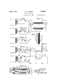
Figure l illustrates a system adapted to half wave rectifiers;
Figures 2 to 5 inclusive are applicable to full wave rectification;
Figures 6 and 7 show a preferred type of transformer Figure 8 is a longitudinal cross-sectional view of a preferred form of rectifier; while Figure 9 is a graph showing voltage and current curves applicable to the specific type of rectifier shown in Figure 8.
Figure l() is a system for operating rectifiers in tandem.
Referring to Figure l, numeral 1 indicates a voltage transformer, the primary of which is energized by a source of alternating current, ordinarily house supply. The terminals of the secondary are connected serially to a rectifying unit 2, shown as of the single wave type and a direct current load 3 indicated conveniently as a battery, the power supply of vacuum tubes or any other load. The rectifier 2 may take any form but is specially applicable to unilateral devices characterized by peak voltages i. e. having sharp voltage ripples due to lack of coincidence between the points of current reversal and cut-off. In order to obviate the effect of the voltage ripples, any one or all of the several expedients described hereinafter may be employed.
The transformer 1 shown is of special design, deriving relatively low .leakage reactance, i. e. tight coupling, by reason of close spacial relation between the various windings. A simplified design is shown in Figures 6 and 7 wherein the secondary winding 4 is wound sandwich fashion, between the two halves 5 and 6 of the primary which are connected in series bringing out the leads S1 and S2, the primary being indicated by leads I)1 and P2. The windings are mounted on the central branch of core 7, built of laminas. It'is apparent that this construction precludes substantial magnetic leakage and as such reduces very materially the effect of peak voltage in the secondary circuit. A series resistance 8 may be employed to translate some of the excess energy derived from the peak voltage, into heat to be harmlessly dissipated. The resistance also materially aids in the voltage regulation of the circuit.
While the unilateral conductor 2 may be of any type, one having the characteristics set forth above is especiall benefited by my invention.` One such rectifier is the colloidal rectifier Aso-called, described and claimed in the application of Andr Serial No. 749,214, filed November 11, 1924, entitled Unilateral conductor for rectifying alternating current and other applications; a section through the rectifier is shown in Figure 8. Referring to this figure, numeral 9 deslgnates a tube or receptacle of a metal passive to concentrated acid e. g. iron, having the exterior surface plated with cadmium or copper. One end of the receptacle is closed by the material forming the tube and the other by a non-corrosive pulverized packing 10 of the character which absorbs and neutralizes acid and is also pervious to air, e. g. magnesium oxide mixed with asbestos fibre. At the bottom of the container, there is located electrode 11 of a metal such as silver which lends itself readily to colloidal or comminuted form and oxldation products which are relatively good conductors of electrical energy. This electrode is firmly secured to the container by rivet 12, preferably of the same material as the anode.
Numeral 13 designates an anode in the form of a quantity of metal, as a powder or colloid, e. g. silver, derived by any known process and resting on this metal is a mass of liquid absorbing material as sand, glasswool or the like. 'The fine metallic particles may be spaced from one another by thoroughly mixing with silica in amorphous form in proportion by volume varying between one part silver to ten parts silica and ten parts silver to one part silica although I prefer the form of silicon dioxide sold under the name of silocel, snpercel or hyilo-supercel combined with an equal quantity of powdered metal. The combined mass is extremely porous offering ready access t0 liquid and packs loosely about the upstanding metallic member referred to hereinafter as cathode, to cause a yielding pressure therewith. For the absorbent 14, I may employ glass-wool felt of thickness approximately one-sixteenth inch and wound about the middle portions of the cathode until the roll is lodged fairly tight within the rece tacle.
orizontal lines 15 denote an acid oxidizing agent completely saturating the absorbent materi. The acid is preferably sulphur-ic having concentration of approximately 1.840 combined with anhydrid as set forth in the Andr ap lication referred to. Centrally disposed o the structure and sunk to considerable depth in the powdered silver is another electrode 16 hereinafter referred to as cathode, preferably in rod form and of a metal, as nickel containing silicon, in percentage rangin between and 32, the alloys of iron-silicon, cobalt-silicon or alloys of tin containing antimony, bismuth, silicon or nickel, any or all of them, characterized by oxidation products which .0perated in conjunction with the anode to cause unidirectional flow of current. A device such as described has the property of rectifying alternating current of relatively large amplitude.
The end of the cathode farther removed from the anode is tapered and terminates in a lead-out wire, the tapered portion being preferably coated with a plastic compound 17, as asphaltum or parain, to prevent creepage of liquid. I may also provide glass rod 18 having a small aperture extending longitudinally and fused about the tapered portion of the cathode and lead-out wire, offering protection to the latter from acid attack. As shown, the top of rod is hollow forming long leakage paths for the acid. The inner surface of the container may also be coated with the same compound. In order further to prevent attraction of liquid, a glass ring 19 similarly coated and interposed between two mica washers 20 is placed upon an absorbent material; the upper washer preferably supports an asbestos member 21. The magnesium oxide filler supports a ci rcular plate 22 of insulating material unaffected by acid, e. g. bakelite, vulcanite or ebonite, secured to the container by metallic ring 23.
The aforesaid coatings of plastic compound largely prevent crecpage of the liquid along the coated surfaces and the absorbent material and absorb what little liquid tends to creep along these surfaces, whereby substantially no liquid escapes to cause damage to exterior surfaces or waste.
CTI
A terminal in the form of a thimble 2/1, preferably of steel, nickel plated, rises upufardly from the center of plate 22, being connected to cathode 16 by lead wire 25 ot a material similar to that of the cathode. The lead preferably passes through the thimble l is secured to the upper' surface thereeit ia suitable manner e. by soldering. lt is apparent that the full or double ivave rectiliers shown in Figures 2 to 5 may comprise two single Wave units placed end to end and secured together in a single container.
lVhen a rectiiier of the colloid type is con-- nected serially in a circuit vto which alternating voltage is applied, and devoid of means for removing the ripples referred to hereinbefore, the voltage available at the output shows peaks of short duration but of considerable strength often reaching a value much greater than the maximum sine wave voltage. These peaks and their eiiqect are illustratively emphasized in Figure 9, Wherein curve L in dot-dash represents the sine voltage, curve Z), in full line the resulting output voltage, similarly, curve c, the sine Wave current, and curve CZ the actual current that is flowing to the load. .it will be noted that the peak e in the voltage curve representing the effect of displacement between the point of zero current and current cut-ofi in the rectifier, gives rise Uo current impulse indicated at f, this impulse occurring in the reverse current Wave.. However, upon the insertion of a transformer having low leakage reactance and the resistance described above, either or both, the electy of the peak voltage is practically nullied or at least reduced in substantial degree.
In lieu of or in addition to the resistance, a capacity connected in shunt as an excess current by-pass may add its ellect to that derived from the loW leakage transformer and series resistance; thus in Figure 2, condenser 26 is shown connected across the line. The circuit is exempliiied with respect to a double Wave rectiiier 27 although it pertains equally Well to a single Wave device; the transformer of special design may be employed to energize the rectifier in Figure l.
Figure 3 is similar to Figure 2 except that the by-pass condenser is omit-ted and the series resistance moved to a shunt position to comprise clement 28.
Figure l shows the combination of a sh unt condenser 26 and resistance 2S, thus combining the lay-passing eii'ect et each et these elements.
Figure 5 illustrates a circuit which provides for a condenser smaller in falue than in Figures 2 and 4 for the same eifectiveness in output. This advantage is gained by employing a transformer 29 which has a voltage transformation greater than instead of comparable to the voltage required to energize the rectii'ier as in prior figures and connecting the shunt condenser 30 across the outside terminals of the secondary. The voltage tor the rectifier is derived from an intermediate tap 8l. lt is apparent that the relatively high potential applied to the condenser inures to the rectifying circuit as a Whole, either by way of a smaller condenser necessary or for a given condenser, a greater reduction oi peak voltage and hence less noise in the radio set or other load.
"the condensers, as utilized in this invention, are to be sharply distinguished from the buier capacities, so-called, employed in con.- nection with gaseous tube rectification inasmuch as the co-action between the butter condenser' and its associated rectilier is entirely diiiierent Afrom that taking place between condensers 2G, 30 and rectiers 2 and 2?. It is apparent that the function of the condenscrs and resistances in 'the various embodiments is to conserve the energy produced by the inductive kick, the condenser holding the momentary rush ot current from discharge until a later and more propitious time and the resistance, dissipating energy by Way ot heat, in either case, removing the excess current trom the load.
Figure l() shows a system for operating tivo rcctiliers in parallel. In this system, the transformer has primary P of an odd number ont layers, so that the inner and outer layers are of the primary coil. Sandwiched in between these layers, are tivo secondary layers S1 and S2. lt will be noted that no tivo primary or secondary layers are adjacent. Primary layers P are connected in series as shown to make a single electrical unit. Secondary layers S1 and S2 have separate leads 36 and 37 to rectiiers 2. These rcctiiiers are connected together by resistance 35, from the mid point of Which, lead 3S is taken. rlhe resistance 35 tends to equalize the loads on rectiiiers 2 and prevents any from taking more than its share ot the loa d. l`he lead 39 goes from battery 3, to which 3S is connected, to both secondaries S1 and S2. rlhus on one end, the secondaries are separate While at the other end they are in parallel. ln this Way, my invention may be carried out to include more than tivo rectiA ers in parallel. lt is Obvious that for more than two rcctitiers in parallel, resistance 35 would be replaced by equal resistances coming from the rectiliers to a common output.
The systems as described, enable the procurement in the output circuit of a voltage def-reid et peaks resulting trom the tact that the point ot current cut-olii is delayed beyond the peint of current reversal in the rectiiier. is apparent that it desired, lilters oi suitable design may be added subsequent to the rectifier' for the purpose of smoothing whatever voltage ripple remains.
I claim:
1. A rectifying system comprising a plurality of rectifiers whose points. of current cat-oil:` and current reversal are not coincident, and a transformer of low leakage reactance, the said transformer having a plurality of secondaries, each of the said secondaries being disposed between primary coils, each of said secondaries being connected to a rectifier, the rectifiers having their output terminals connected to the output line throu h a resistance.
2. A rectifymg system comprising a rectier whose points of cut-0H and current reversal are not coincident, said rectifier having electrode means of one polarity, and additional electrode means of opposite polarity, a source of alternating current, i11- cluding an inductance, and a direct current load circuit, an electrode means of said rectifier of one polarity being connected to a fixed point on said inductance, one terminal of said load circuit being connected to an electrode means of opposite polarity of said rectifier, the other terminal of said load circuit being connected to another point on said inductance, and a resistance connected across two spaced points on said inductance.
3. A rectifying system comprising a rectifier whose points of cut-off and current reversal are not coincident, said rectifier having electrode means of one polarity and additional electrode means of opposite polarity, a source of alternating current including an inductance, a circuit comprising an electrode means of one polarity of said rectifier, additional electrode means of opposite polarity of said rectifier, and a direct current load circuit in series connected across said inductance, and a resistance connected in parallel across said inductance.
4. A rectifying system comprising a rectifier whose points of cut-01T and current reversal are not coincident, said rectifier having electrode means of one polarity, and additional electrode means of opposite polarity, a source of alternating current including an inductance, and a direct current load circuit, an electrode means of said rectifier of one polarity being connected to a fixed point on said inductance, one terminal of said load circuit being connected to an electrode means of opposite polarity of said rectifier, the other terminal of said load circuit being connected to another point on said inductance, a resistance connected across two spaced points on said inductance, and a condenser connected across said resistance.
5. A rectifying system comprising a rectifier whose points of cut-ofi` and current reversal are not coincident, said rectifier having electrode means of one polarity and additional electrode means of opposite polarity, a transformer having a prnnary and a secondary, said transformer having a low leakage reactance, a circuit comprising an electrode means of one polarity of said rectifier, an electrode means of opposite polarity of said rectifier, and a direct current load circuit in series connected across the secondary of said transformer, and a resistance connected in arallel with said secondary.
6. A rectifying system com rising a rectifier whose points of cut-o and current reversal are not coincident, said rectifier having a pair of electrodes of one polarity and additional electrode means cooperating therewith to permit current {iow only in one direction with respect to said electrodes, a source of alternating current including an inductance, said inductance having its ends connected to said pair of rectifier electrodes, respectively, a direct current circuit having a pair of conductors connected to said additional electrode means of said rectifier and a point intermediate the ends of said inductance, respectively, a load connected in said direct current circuit, and a resistance connected across said inductance.
In testimony whereof, I have signed my name to this specification this 15th day of March, 1928.
WILFRED K. FLEMING.
Priority Applications (1)
| Application Number | Priority Date | Filing Date | Title |
|---|---|---|---|
| US263141A US1908336A (en) | 1928-03-20 | 1928-03-20 | Rectifying system |
Applications Claiming Priority (1)
| Application Number | Priority Date | Filing Date | Title |
|---|---|---|---|
| US263141A US1908336A (en) | 1928-03-20 | 1928-03-20 | Rectifying system |
Publications (1)
| Publication Number | Publication Date |
|---|---|
| US1908336A true US1908336A (en) | 1933-05-09 |
Family
ID=23000537
Family Applications (1)
| Application Number | Title | Priority Date | Filing Date |
|---|---|---|---|
| US263141A Expired - Lifetime US1908336A (en) | 1928-03-20 | 1928-03-20 | Rectifying system |
Country Status (1)
| Country | Link |
|---|---|
| US (1) | US1908336A (en) |
Cited By (2)
| Publication number | Priority date | Publication date | Assignee | Title |
|---|---|---|---|---|
| US2831121A (en) * | 1952-09-27 | 1958-04-15 | Bendix Aviat Corp | Apparatus for detecting alpha and beta rays |
| US3363109A (en) * | 1963-01-23 | 1968-01-09 | John R. Wilhelm | Model railroad electric power supplies and distribution equipment |
-
1928
- 1928-03-20 US US263141A patent/US1908336A/en not_active Expired - Lifetime
Cited By (2)
| Publication number | Priority date | Publication date | Assignee | Title |
|---|---|---|---|---|
| US2831121A (en) * | 1952-09-27 | 1958-04-15 | Bendix Aviat Corp | Apparatus for detecting alpha and beta rays |
| US3363109A (en) * | 1963-01-23 | 1968-01-09 | John R. Wilhelm | Model railroad electric power supplies and distribution equipment |
Similar Documents
| Publication | Publication Date | Title |
|---|---|---|
| US2403891A (en) | Load current control | |
| US4543554A (en) | System for the elimination of radio interference and method for its manufacture | |
| GB1388481A (en) | Ozonizer electric supply systems | |
| US2406045A (en) | Inductance device | |
| US2985812A (en) | Encapsulated power supply | |
| US3748618A (en) | Radio frequency choke | |
| US1908336A (en) | Rectifying system | |
| US3112439A (en) | Flux oscillator transformer with variable shunt | |
| US1920618A (en) | Voltage regulating apparatus | |
| US2000189A (en) | Regulated rectifier | |
| US2564881A (en) | Transformer rectifier | |
| US1947242A (en) | Electric valve converting apparatus | |
| JPS56162972A (en) | Switching electric power source device | |
| US1839869A (en) | Voltage regulator for radiotransmitters | |
| US2727160A (en) | Pulse generator | |
| US1766051A (en) | Rectifier circuit | |
| US2096801A (en) | Power transformer | |
| US1717070A (en) | Rectifying system | |
| US1916424A (en) | Filter system | |
| US3164784A (en) | Push-pull oscillator power supply having parallel-connected transistors | |
| US3275920A (en) | High voltage supply circuit | |
| US2253962A (en) | Reactor | |
| US1916462A (en) | Commutating electric machine | |
| US1607075A (en) | Electrolytic rectifier | |
| US1182685A (en) | Current-rectifier system. |