US1908325A - Kite - Google Patents
Kite Download PDFInfo
- Publication number
- US1908325A US1908325A US421989A US42198930A US1908325A US 1908325 A US1908325 A US 1908325A US 421989 A US421989 A US 421989A US 42198930 A US42198930 A US 42198930A US 1908325 A US1908325 A US 1908325A
- Authority
- US
- United States
- Prior art keywords
- kite
- flying
- rudder
- lines
- wind
- Prior art date
- Legal status (The legal status is an assumption and is not a legal conclusion. Google has not performed a legal analysis and makes no representation as to the accuracy of the status listed.)
- Expired - Lifetime
Links
- 230000009187 flying Effects 0.000 description 102
- 231100000773 point of departure Toxicity 0.000 description 9
- 238000010276 construction Methods 0.000 description 5
- 241000969130 Atthis Species 0.000 description 1
- 238000004026 adhesive bonding Methods 0.000 description 1
- 210000000481 breast Anatomy 0.000 description 1
- 230000000694 effects Effects 0.000 description 1
- 239000013013 elastic material Substances 0.000 description 1
- 239000004744 fabric Substances 0.000 description 1
- 239000000463 material Substances 0.000 description 1
- 230000004048 modification Effects 0.000 description 1
- 238000012986 modification Methods 0.000 description 1
Images

Classifications
-
- A—HUMAN NECESSITIES
- A63—SPORTS; GAMES; AMUSEMENTS
- A63H—TOYS, e.g. TOPS, DOLLS, HOOPS OR BUILDING BLOCKS
- A63H27/00—Toy aircraft; Other flying toys
- A63H27/08—Kites
Definitions
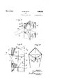
- kites heretofore made and the usual cloth or paper flying bands have merely been tied to theend of a string 9 and 10.
- kite oi the present invention is proshown in Fig. 6 to receive the rudder bar 12; vided with a rudder which is substantially
- the notches 11 are preferably rounded at fixed relatively to the kite and the kite the inner ends to lit the seating portions of strings are so fastened to the kite that they the rudder bar so that the rudder may beset may be manipulated by the person who 1s at different angles relativeiy to the flying flying the kite to move the kite from the surfaces.
- the rudder bar may be 10 drawings and will particularly be pointed neld'in the notches by any suitable means out in the claims. It is to be understood such as the rubber bands 13 which convenhowever that the specification and drawings iently pass through holes 1 1 in the uprights, are to be considered in no sense limiting, with the ends of the bandsaround therud a.
- FIG. 1 is a perspective view of a box kite tion by any su table means such as stay lines with a rudder and flying lines, illustrating 16 which are tied to the normally front and one "form of the invention.
- Small 0 Fig 2 i a perspgctive f a kit si ilar to holes 17 in the bases of the front and rear the kite shown in Fig. 1 in a rotated posiuprights 1 and 4 may receive the ends of the ti 7 stay lines.
- kites such as springs or rubber bands 18 are preftaiwd Osition to Show the action fth d stay lines 16 so that, although they rudder der with respect to the wind in this posi- 15 substantially d f fl ly to the y".
- inueneoasucien sowin ue 0 1S deball of the tan Of the klte' springs or rubber bands 18 will returnit '0 its normal position.
- the rudder is preferably made with. a peripherial piece 19 connected to the rudder bar 12 in any suitable way as by hav- Fig. 6 is a side View of Fig. 5.
- Fig. 7 is an elevation of a modified torm of the kite.
- Fig. 8 is a longitudinal section through 45 the k Shown y ing the ends of the piece 19 seated in or 39 ,Sectlon on the l lookmg passing through holes 20 in the rudder bar 111 the illrecilon of the arrows- 12.
- the space between the peripherial piece AS is illustrated in l 2 and the 19 and the rudder bar 12 is filled in by web kite consists of the uprights 1, 2, 3 and 1 21 hi h atch s the wind a d xe ts an 5 which are braced by the braces 5, 6, 7 and 8, eifort on the kite'which can be varied in any direction as the kite is rotated in its flying position.
- the stay lines 16 may conveniently be fastened to the rudder for all practical purposes as is shown in Fig. 6, i. e., by having the stay lines pass around the pe ripherial piece 19 in one or more loops 22 which, when drawn, tightly grip the pe ripherial piece 19 and hold the rudder in the desired position but the rudder may easily be set at the desired angle relative to the flying surfaces by loosening the loops 22 and then tightening them again after the rudder has been set in the desired position.
- the kite When the kite is in the normal flying position it is in the position shown in Figs. 1 and 3 with the wind moving in the direction of the arrows 23. WVith the rudder set in the position shown in Figs. 1 and 2 it will act as an elevator because the wind will impinge upon the rudder 15 to depress the tail portion of the kite and this will make the kite tilt so that it will tend to rise in the air. In this position the flying lines 24 and 25 pass from the sides of the kite downwardly toward the ground and the kite will rise in the air as would'a normal box kite. If, however, the flying line 24 is pulled v and the flying line 25 is correspondingly released, the kite will rotate toward the position shown in Fig.
- the rudder may therefore be considered to be a guiding surface attached to the kite and adapted to act either as an elevator or a deflector or both depending upon its position in the wind.
- the guiding surface 15 acts as an elevator when the kite is in the position shown in Figs. 1 and 8 and the guiding surface 15 acts as a deflector when the kite is in the position shown in Fig. 2.
- Fig. 4 shows the kite rotated beyond the 90 point shown in Fig. 2 in which position the rudder acts to elevate the tail as well as turn the kite. In intermediate positions between the position shown in Fig. 1 and the position shown in Fig.
- the rudder as both an elevator to depress the tail and a deflector, and the flying lines serve to change the position of the guiding surface 15 in the wind while the kite is flying to make it functioneither as an elevator or a deflector or both in a great variety of positions and combinations, by rotating the kite to change the position of the kite which in turn changes the osition of the guiding surface. Also, by further pulling the flying line 24 so as to rotate the kite beyond the position shown in Fig. 2, the rudder or defleeting surface moves beyond the point of depression and tends to elevate the tail as well as to turn the kite as above stated.
- the flying lines 24 and 25 may be fastened to the side uprights 2 and 3 but in the preferred form the flying lines pass around the kite and are fastened to the rear upright e at about the point 27 so as to givethe rotation shown in Fig. 4:.
- means are provided to keep the flying lines in the same relative relation to the kite when the kite is rotated in the air sothat no matter in what position the kite may be, the flying lines will come from the kite at substantially constant points of departure.
- Such means are preferably the retaining lines 28 which are fastened at one end 29 to the flying lines and at the other end 30 to the side uprights 2 and 3'near the bases of the side uprights.
- the retaining lines together with the portions of the flying lines which extend between the points 29 and the point 27 form a harness and it will be understood that when the kite is flying, the wind is always pressing the kite into the harness so that the harness is always supporting the kite from the rear.
- This means of harnessing the kite gives greater strength to the kite while in flight than would be the case if flown by a single string or point of attachment as might normally be indicated at 27.
- the separate rudder of the form of kite shown in Figs. 13 can be eliminated by making the rudder ordeflector an integral part of the kite in a variety of ways.
- One form of this is shown in Figs. 'Z-9 in which a pair of surfaces 31 and 32 of band, 9 are set out of the normal line of the other flying sur faces by fastening them together along the line 33 so that an accentuated angle is given these surfaces for the purpose of deflecting the head of. the kite to one side or the other as the kite is rotated in flight.
- the surfaces 31 and 32 will tend to make the kite rise in the air when the kite is flying normally but when either of the flying lines 24 or 25 is pulled to rotate the kite, the wind will impinge on the flying surfaces to deflect the head of the kite either to the right or left as the case may be.
- kite shown in Figs. 7-9 is flown and guided in the same manner as the kite shown in Figs. 1-3, i. e., by pulling on either of the flying lines 24 or 25 to rotate the kite, which changes the position of the guiding surfaces 31 and 32 relative to the wind to cause them to act as deflectors to guide the kite through the wind.
- the uprights are preferably enlarged somewhat at the parts 37 which are in the center of the flying surfaces 9 and 10.
- the braces 5-8 engage the uprights at the parts 37 where the uprights are the strongest and the sloping parts 38 of the uprights enable the braces to be wedged into place against the tension of the material from which the flying surfaces are made.
- This forms a rigid structure and, due to the added strength of the enlarged parts 37, there is very little liklihood that the uprights Will be broken.
- this same construction is used for the lower part of the'kite but for the upper part of the kite where the angular surfaces 31 and 32 are used, two sets of braces 5 and 6 and 39 and 40 are preferably used to strengthen the angular surfaces.
- kite presenting flying surfaces and having a rudder substantially fixed relatively to the flying surfaces, and a flying line passing from each side of the kite to the ground and adapted to move the kite about its longitudinal axis of flight from the ground to change the positionof the rudder in the Wind to guide the kite.
- kite presenting flying surfaces and having a rudder substantially fixed relatively to the flying surfaces and flying lines passing from the sides of the kite on either side of the longitudinal axis of flight to the ground and adapted to move the kite from the ground to change the position of the rudder in the wind to guide the kite.
- kite presenting flying surfaces and having a rudder substantially fixed relativelyto the flying surfaces, flying lines passing from the kite to the ground and adapted to move the kite from the ground while the kite is flying to change the position of the rudder in the wind, and means to keep the flying linesat substantially the same point of departure relative to the kite as the kite moves.
- a kite having flying lines passing from the kite toward the ground and adapted to rotate the kite in the air and passing around the kite to support it against the wind and arranged to remain on the kite as the kite is rotated. 7
- kite presenting flying surfaces and having a rudder substantially fixed relatively to the flying surfaces, flying lines passing from the kite to the ground and adapted to rotate the kite from the ground while the kite is flying to change the position of the rudder in the Wind, and retaining lines fastened to the kite and to the flying lines to keep the flying lines at substantially the same point of departure relative to the kite as the kite rotates.
- kite presenting normally rear and side uprights and flying surfaces and having a rudder substantiallyfiXed relatively to the flyingzsurfaces, and flying lines fastened to the normally rear upright and passing around the side uprights to the ground and adapted to move the kite from the ground while the kite is flying to change the position of the rudder in the wind to guide the kite.
- kite presenting normally rear and side uprights and flying surfaces and having a rudder substantially fixed relatively to the flying surfaces,-flying lines fastened to the normally rearupright and passing aroundthe side uprights to the ground and adapted to move the kite from the ground While the kite is flying to change the position of the rudder inthe Wind to guide the kite, and means to keep the flying lines at substantially the same point of departure relative to the kite as the kite moves.
- kite presenting normally rear and side uprights and flying surfaces and having a rudder substantially fixed relatively to the flying surfaces, flying lines fastened to the normally rear upright and passing around the side uprights to the ground and adapted to move the kite from the ground While the kite is flying to change the position of the rudder in the Wind to guide the kite, and retaining lines fastened to the flying lines and to the side uprights to keep the flying lines at substantially the same point of departure relative to the kite as the kite moves. 7
- kite presenting normally rearv and side uprights and flying surfaces and having a rudder substantially fixed relatively to the flying surfaces, flying lines fastened to the normally rear upright and passing around the side uprights to the ground and adapted to move the kite from the ground While the kite is flying to change the position of the rudder in the Wind to guide the kite, and retaining lines fastened to the flying lines and to the side uprights near their bases to keep the flying lines at substantially the same point of departure relative to the kite as the kite moves.
- kite having flying surfaces, a guiding surface attached thereto and set to act either as an elevator or as a deflector depending upon its position in the Wind, and a means to change the posi tion of the guiding surface in the Wind While the kite isflying to make it function either as an elevator or a deflector.
- kite having fly ing surfaces, a guiding surface attached thereto and set to act either as an elevator or a deflector depending upon its position in the Wind, and a means to change the position of the kite to change the position of the guiding surface in the Wind While the kite is flying to make it function either as an elevator or a deflector and deflector.
- kite presenting flying surfaces and having a rudder substantially fixed relatively to the flying surfaces, and means to rotate the kite about its longitudinal aXis of flight from the ground to change the position of the rudder in the Wind to guide the kite.
- kite presenting flying surfaces and having a rudder substantially fixed relatively to the flying surfaces, and flying lines passing from the kite to the ground and adapted to move the kite about its longitudinal axis of flight from the ground to change the position of the rudder in the Wind to guide the kite.
Landscapes
- Toys (AREA)
Description
H. DE HAVEN May 9, 1933.
KITE
Filed Jan. 20, 1930 2 Sheets-Sheet l INVENTOR @e M ATTORNEYS.
May 9, 1933 H. DE HAVEN KITE Filed Jan. 20, 1950 2 Sheets-Sheet 2 g INZNTOR I ATTORNEYS.
'3? F10; 4 i a l d f th kit i a erably interposed between the parts of the Patented May 9, 1933 l I UNITEDSTATES PATENT ori ice i Application filed. January 20, 1930. Serial No. 421,989.
The majority of the kites heretofore made and the usual cloth or paper flying bands have merely been tied to theend of a string 9 and 10. i L I y and sailed in the air and they have made no In the form of kite shown in F1gs. 1-o, means for guiding them during their movethe bottoms of the two opposite upright-s,
ment through the current of air in which preferably the two uprights wh ch are the th were fl in side uprights 2 and 3 are notched at 11, as is The kite oi the present invention is proshown in Fig. 6 to receive the rudder bar 12; vided with a rudder which is substantially The notches 11 are preferably rounded at fixed relatively to the kite and the kite the inner ends to lit the seating portions of strings are so fastened to the kite that they the rudder bar so that the rudder may beset may be manipulated by the person who 1s at different angles relativeiy to the flying flying the kite to move the kite from the surfaces. In the term of kite shown in Fig. ground while it is flying to make the rudder 2, the rudder s intended to yield slightly lunction either as an elevator or a deflector when the kite is caught in a sudden gust of N to guide the kite across the wind or to wgnd and thereit'ore the contacting P01131011? 6 cause it to perform evolutions in the air. F o tne IlObjChGS and rudder, in this fprm 01 These and other purposes and features or into, may roe greased so that should tne rudthe invention and the, construction of the der move slightly under the influence of a kite will more fully appear from the tolsudden gustu of wind it will return to its F lowing description and the accompanying normal position. The rudder bar may be 10 drawings and will particularly be pointed neld'in the notches by any suitable means out in the claims. It is to be understood such as the rubber bands 13 which convenhowever that the specification and drawings iently pass through holes 1 1 in the uprights, are to be considered in no sense limiting, with the ends of the bandsaround therud a.
but merelv as illustrating the invention. der bar. In the lorm of kite shown n Fig.
In the drawings: 1 the rudder 1s neld in firmly fiX ed posi- Fig. 1 is a perspective view of a box kite tion by any su table means such as stay lines with a rudder and flying lines, illustrating 16 which are tied to the normally front and one "form of the invention. rear uprights 1 and 1-, respectively. Small 0 Fig 2 i a perspgctive f a kit si ilar to holes 17 in the bases of the front and rear the kite shown in Fig. 1 in a rotated posiuprights 1 and 4 may receive the ends of the ti 7 stay lines. In the toi'm of kite shown 111 Fig; 3 i a l it di al s ction th ough Fig. ,2, pieces of springy or elastic material one 6 the kites. such as springs or rubber bands 18 are preftaiwd Osition to Show the action fth d stay lines 16 so that, although they rudder der with respect to the wind in this posi- 15 substantially d f fl ly to the y". tion. nfgl' surcfacefs 1b Indy yielld tsligfhtiy 2%:
inueneoasucien sowin ue 0 1S deball of the tan Of the klte' springs or rubber bands 18 will returnit '0 its normal position.
The rudder is preferably made with. a peripherial piece 19 connected to the rudder bar 12 in any suitable way as by hav- Fig. 6 is a side View of Fig. 5.
Fig. 7 is an elevation of a modified torm of the kite. f
Fig. 8 is a longitudinal section through 45 the k Shown y ing the ends of the piece 19 seated in or 39 ,Sectlon on the l lookmg passing through holes 20 in the rudder bar 111 the illrecilon of the arrows- 12. The space between the peripherial piece AS is illustrated in l 2 and the 19 and the rudder bar 12 is filled in by web kite consists of the uprights 1, 2, 3 and 1 21 hi h atch s the wind a d xe ts an 5 which are braced by the braces 5, 6, 7 and 8, eifort on the kite'which can be varied in any direction as the kite is rotated in its flying position. The stay lines 16 may conveniently be fastened to the rudder for all practical purposes as is shown in Fig. 6, i. e., by having the stay lines pass around the pe ripherial piece 19 in one or more loops 22 which, when drawn, tightly grip the pe ripherial piece 19 and hold the rudder in the desired position but the rudder may easily be set at the desired angle relative to the flying surfaces by loosening the loops 22 and then tightening them again after the rudder has been set in the desired position.
When the kite is in the normal flying position it is in the position shown in Figs. 1 and 3 with the wind moving in the direction of the arrows 23. WVith the rudder set in the position shown in Figs. 1 and 2 it will act as an elevator because the wind will impinge upon the rudder 15 to depress the tail portion of the kite and this will make the kite tilt so that it will tend to rise in the air. In this position the flying lines 24 and 25 pass from the sides of the kite downwardly toward the ground and the kite will rise in the air as would'a normal box kite. If, however, the flying line 24 is pulled v and the flying line 25 is correspondingly released, the kite will rotate toward the position shown in Fig. 2 with the wind con1 ing in the direction of the arrow 26 and this will cause the kite to move across the wind toward the left. This will happen when the kite has been rotated sufliciently so that the normally rear upright l has moved toward the position of the normally side upright 2. When the flying line 25 is pulled and the flying line has been correspondingly released sufficiently to cause the normally rear upright l to move toward the position of the normally side upright 3, the rudder will have the other position which will cause the kite to move to the right across the wind when it is coming in the direction of the arrow 26. The rudder may therefore be considered to be a guiding surface attached to the kite and adapted to act either as an elevator or a deflector or both depending upon its position in the wind. The guiding surface 15 acts as an elevator when the kite is in the position shown in Figs. 1 and 8 and the guiding surface 15 acts as a deflector when the kite is in the position shown in Fig. 2. Fig. 4: shows the kite rotated beyond the 90 point shown in Fig. 2 in which position the rudder acts to elevate the tail as well as turn the kite. In intermediate positions between the position shown in Fig. 1 and the position shown in Fig. 2, the rudder as both an elevator to depress the tail and a deflector, and the flying lines serve to change the position of the guiding surface 15 in the wind while the kite is flying to make it functioneither as an elevator or a deflector or both in a great variety of positions and combinations, by rotating the kite to change the position of the kite which in turn changes the osition of the guiding surface. Also, by further pulling the flying line 24 so as to rotate the kite beyond the position shown in Fig. 2, the rudder or defleeting surface moves beyond the point of depression and tends to elevate the tail as well as to turn the kite as above stated.
The flying lines 24 and 25 may be fastened to the side uprights 2 and 3 but in the preferred form the flying lines pass around the kite and are fastened to the rear upright e at about the point 27 so as to givethe rotation shown in Fig. 4:. In the preferred form of kite shown in the drawings means are provided to keep the flying lines in the same relative relation to the kite when the kite is rotated in the air sothat no matter in what position the kite may be, the flying lines will come from the kite at substantially constant points of departure. Such means are preferably the retaining lines 28 which are fastened at one end 29 to the flying lines and at the other end 30 to the side uprights 2 and 3'near the bases of the side uprights. The retaining lines together with the portions of the flying lines which extend between the points 29 and the point 27 form a harness and it will be understood that when the kite is flying, the wind is always pressing the kite into the harness so that the harness is always supporting the kite from the rear. This is an advantage because the strain on the kite in some maneuvers is excessive and, being pressed into the loop or harness by the wind, the pull of the string is distributed to all four uprights; the uprights 2, 3 and i in normal flight taking the strain by direct pressure from the loop of the harness and upright 1 taking the strain through the cross piece or brace 6. This means of harnessing the kite gives greater strength to the kite while in flight than would be the case if flown by a single string or point of attachment as might normally be indicated at 27. v
In a modified form of the kite the separate rudder of the form of kite shown in Figs. 13 can be eliminated by making the rudder ordeflector an integral part of the kite in a variety of ways. One form of this is shown in Figs. 'Z-9 in which a pair of surfaces 31 and 32 of band, 9 are set out of the normal line of the other flying sur faces by fastening them together along the line 33 so that an accentuated angle is given these surfaces for the purpose of deflecting the head of. the kite to one side or the other as the kite is rotated in flight.
With such a construction surfaces 31 and 32 will have a greater angle to the wind than the normal flying surfaces and will therefore act to elevate the head of the kite and take the place of the fixed rudder which tends to depress the tail of the kite to accomplish the same effect, i. e., a tendency to cause the kite to climb. And in the same way that the separate rudder deflects the tail of the kite when turned, so these set surfaces will cause the head of the kite to deflect to give direction to the kite as it passes through the wind when the kite is turned. Thus the surfaces 31 and 32 will tend to make the kite rise in the air when the kite is flying normally but when either of the flying lines 24 or 25 is pulled to rotate the kite, the wind will impinge on the flying surfaces to deflect the head of the kite either to the right or left as the case may be.
The above indicated construction may be accomplished by gluing together the necessary portions of the surfaces 31 and 32 which may be'strengthened by the stitches 34 along the line 33 to hold the surfaces together. To further strengthen the structure atthis point, an angular strut may be inserted as shown in Figs. 7 and 9 and additional stitches 36 may be used in front of the angular strut to form a sleeve into which the angular strut will fit. V
The form of kite shown in Figs. 7-9 is flown and guided in the same manner as the kite shown in Figs. 1-3, i. e., by pulling on either of the flying lines 24 or 25 to rotate the kite, which changes the position of the guiding surfaces 31 and 32 relative to the wind to cause them to act as deflectors to guide the kite through the wind. I
By reversing this form of kite and fasteningthe flying loop to what is known as the tail in Fig. 7 the deflecting effort of the tail can be made to act on the tail in the same way as the rudder or deflector shown in Fig. 1. r
In the form of kite shown in Figs. 13, the uprights are preferably enlarged somewhat at the parts 37 which are in the center of the flying surfaces 9 and 10. The braces 5-8 engage the uprights at the parts 37 where the uprights are the strongest and the sloping parts 38 of the uprights enable the braces to be wedged into place against the tension of the material from which the flying surfaces are made. This forms a rigid structure and, due to the added strength of the enlarged parts 37, there is very little liklihood that the uprights Will be broken. In the form of kite shown in Figs. 7-9 this same construction is used for the lower part of the'kite but for the upper part of the kite where the angular surfaces 31 and 32 are used, two sets of braces 5 and 6 and 39 and 40 are preferably used to strengthen the angular surfaces.
From the preceding specification it will be understood that the invention may have several different forms and it is recognized that many other modifications may also be made, both in construction and application ofthe invention, and it is therefore to be understood that the invention is to be construed as broadly as the claims, taken in conjunction with the prior art, may allow.
I claim:
1. The combination of a kite presenting flying surfaces and having a rudder substantially fixed relatively to the flying surfaces, and a flying line passing from each side of the kite to the ground and adapted to move the kite about its longitudinal axis of flight from the ground to change the positionof the rudder in the Wind to guide the kite.
2. The combination of a kite presenting flying surfaces and having a rudder substantially fixed relatively to the flying surfaces and flying lines passing from the sides of the kite on either side of the longitudinal axis of flight to the ground and adapted to move the kite from the ground to change the position of the rudder in the wind to guide the kite. 3. The combination of a kite presenting flying surfaces and having a rudder substantially fixed relativelyto the flying surfaces, flying lines passing from the kite to the ground and adapted to move the kite from the ground while the kite is flying to change the position of the rudder in the wind, and means to keep the flying linesat substantially the same point of departure relative to the kite as the kite moves.
4. A kite having flying lines passing from the kite toward the ground and adapted to rotate the kite in the air and passing around the kite to support it against the wind and arranged to remain on the kite as the kite is rotated. 7
5. The combination'of a kite presenting flying surfaces and having a rudder substantially fixed relatively to the flying surfaces, flying lines passing from the kite to the ground and adapted to rotate the kite from the ground while the kite is flying to change the position of the rudder in the Wind, and retaining lines fastened to the kite and to the flying lines to keep the flying lines at substantially the same point of departure relative to the kite as the kite rotates.
6. The combination of a kite presenting normally rear and side uprights and flying surfaces and having a rudder substantiallyfiXed relatively to the flyingzsurfaces, and flying lines fastened to the normally rear upright and passing around the side uprights to the ground and adapted to move the kite from the ground while the kite is flying to change the position of the rudder in the wind to guide the kite.
7. The combination of a kite presenting normally rear and side uprights and flying surfaces and having a rudder substantially fixed relatively to the flying surfaces,-flying lines fastened to the normally rearupright and passing aroundthe side uprights to the ground and adapted to move the kite from the ground While the kite is flying to change the position of the rudder inthe Wind to guide the kite, and means to keep the flying lines at substantially the same point of departure relative to the kite as the kite moves. 8.-The combination of av kite presenting normally rear and side uprights and flying surfaces and having a rudder substantially fixed relatively to the flying, surfaces, flying lines fastened to the normally rear upright and passing around the side. uprights to the ground and adapted to move the kite. from the ground While the kite is flying to change the position of the rudder in the Wind to guide the kite, and retaining lines fastened to the flying lines to keep the flying lines at substantially the same point of departure relative to the kite as the kite moves.
9. The combination of a kite, presenting normally rear and side uprights and flying surfaces and having a rudder substantially fixed relatively to the flying surfaces, flying lines fastened to the normally rear upright and passing around the side uprights to the ground and adapted to move the kite from the ground While the kite is flying to change the position of the rudder in the Wind to guide the kite, and retaining lines fastened to the flying lines and to the side uprights to keep the flying lines at substantially the same point of departure relative to the kite as the kite moves. 7
10. The combination of a kite presenting normally rearv and side uprights and flying surfaces and having a rudder substantially fixed relatively to the flying surfaces, flying lines fastened to the normally rear upright and passing around the side uprights to the ground and adapted to move the kite from the ground While the kite is flying to change the position of the rudder in the Wind to guide the kite, and retaining lines fastened to the flying lines and to the side uprights near their bases to keep the flying lines at substantially the same point of departure relative to the kite as the kite moves.
11. The combination of. a kite having flying surfaces, a guiding surface attached thereto and set to act either as an elevator or as a deflector depending upon its position in the Wind, and a means to change the posi tion of the guiding surface in the Wind While the kite isflying to make it function either as an elevator or a deflector.
12. The combination of a kite having fly ing surfaces, a guiding surface attached thereto and set to act either as an elevator or a deflector depending upon its position in the Wind, and a means to change the position of the kite to change the position of the guiding surface in the Wind While the kite is flying to make it function either as an elevator or a deflector and deflector. v
13. The combination of a kite having flying surfaces, a guiding surface attached thereto and set to act either as an elevator or a deflector depending upon its position in the Wind, and a means to rotate the kite to change the position of the guiding surface in the WindLWhile the kite, is flying to make it function either as an elevator or a deflector- I .14. The combination of a kite having flying surfaces, a guiding surface attached thereto and set to act as an elevator when the kite is in normal flight and to act as a rudder when the kite is rotated and a means to rotate the kite from the ground While the kite is flying to guide the kite across the Wind.
15. The combination of a box kite and a harness for flying the kite and supporting the kite from the rear While the kite is flying and meansto move the kite about its longitudinal axisof flight While flying.
16. The combination of a box kite and flying lines leaving the kite at the sides thereof whereby the kite may be rotated in the air about its longitudinal axis offlight.
17. The combination of a box kite and flying lines leaving the kite at the sides thereof and passing toward the ground and arranged to permit the kite'to be rotated more than 90 about its longitudinal axis of flight.
18. The combinationof a box kite, flying lines leaving the kite at thesides of the kite whereby the kite may be rotated in the air about its longitudinal axis of flight and a {udder extending between the sides of the .nte.
19. The combination of a box kite, flying lines fastened to the rear of the kite and passing around the kite so that they leave the kite at the sides When the kite is flying normally whereby the kite may be rotated in the air, and retaining lines to keep the flying lines at substantially the same point of departure relative to the kite as the kite rotates.
20. The combination of abox kite, flying lines fastened to the rear of the kite and passing around'the kite so that they leave the kite at thesides When the kite, is flying normally whereby the kite may be rotated in the air, and retaining lines fastened to the flying lines to keep the flying lines at substantially the same, point of departure relativeto the kite as the kite rotates.
21. The combination of ackite presenting flying surfaces stantially fixed relatively to the flying sur faces. and means to move the kite about its longitudinal axis of flight from the ground or both an elevator to change the position of the rudder in the Wind to guide the kite.
and having a rudder'sub- 22. The combination of a kite presenting flying surfaces and having a rudder substantially fixed relatively to the flying surfaces, and means to rotate the kite about its longitudinal aXis of flight from the ground to change the position of the rudder in the Wind to guide the kite.
23. The combination of a kite presenting flying surfaces and having a rudder substantially fixed relatively to the flying surfaces, and flying lines passing from the kite to the ground and adapted to move the kite about its longitudinal axis of flight from the ground to change the position of the rudder in the Wind to guide the kite.
In testimony that I claim the foregoing, I have hereunto set my hand this 18th day of January, 1930.
HUGH DE HAVEN.
Priority Applications (1)
| Application Number | Priority Date | Filing Date | Title |
|---|---|---|---|
| US421989A US1908325A (en) | 1930-01-20 | 1930-01-20 | Kite |
Applications Claiming Priority (1)
| Application Number | Priority Date | Filing Date | Title |
|---|---|---|---|
| US421989A US1908325A (en) | 1930-01-20 | 1930-01-20 | Kite |
Publications (1)
| Publication Number | Publication Date |
|---|---|
| US1908325A true US1908325A (en) | 1933-05-09 |
Family
ID=23672919
Family Applications (1)
| Application Number | Title | Priority Date | Filing Date |
|---|---|---|---|
| US421989A Expired - Lifetime US1908325A (en) | 1930-01-20 | 1930-01-20 | Kite |
Country Status (1)
| Country | Link |
|---|---|
| US (1) | US1908325A (en) |
Cited By (4)
| Publication number | Priority date | Publication date | Assignee | Title |
|---|---|---|---|---|
| US2693330A (en) * | 1952-11-17 | 1954-11-02 | Wilbur E Green | Plastic covered nonrigid winged box kite |
| US2693329A (en) * | 1952-11-17 | 1954-11-02 | Charles E Beachy | Kite frame construction |
| US4078745A (en) * | 1976-10-26 | 1978-03-14 | Carl Edward Knight | Rotary kite |
| US7017859B1 (en) * | 2004-11-23 | 2006-03-28 | Pascual Ricardo A | Method of making a miniature, operable box kite |
-
1930
- 1930-01-20 US US421989A patent/US1908325A/en not_active Expired - Lifetime
Cited By (4)
| Publication number | Priority date | Publication date | Assignee | Title |
|---|---|---|---|---|
| US2693330A (en) * | 1952-11-17 | 1954-11-02 | Wilbur E Green | Plastic covered nonrigid winged box kite |
| US2693329A (en) * | 1952-11-17 | 1954-11-02 | Charles E Beachy | Kite frame construction |
| US4078745A (en) * | 1976-10-26 | 1978-03-14 | Carl Edward Knight | Rotary kite |
| US7017859B1 (en) * | 2004-11-23 | 2006-03-28 | Pascual Ricardo A | Method of making a miniature, operable box kite |
Similar Documents
| Publication | Publication Date | Title |
|---|---|---|
| US1858460A (en) | Aerial toy | |
| US2124992A (en) | Airplane kite | |
| US2484096A (en) | Kite | |
| US3746286A (en) | Kite structure | |
| US2035730A (en) | Airplane kite | |
| US1908325A (en) | Kite | |
| US3241793A (en) | Kites | |
| US2221012A (en) | Toy glider | |
| US3801052A (en) | Sailplane | |
| US3711045A (en) | Kites | |
| US1507192A (en) | Toy airplane | |
| US1842434A (en) | Foldable toy monoplane | |
| US3750981A (en) | Man-powered glider aircraft | |
| US1507710A (en) | Miniature-aeroplane construction | |
| US2074327A (en) | Kite | |
| US3514059A (en) | Turbocopter kite | |
| US1005810A (en) | Kite. | |
| US2483614A (en) | Toy kite | |
| US2595074A (en) | Model airplane glider | |
| US4194709A (en) | Mechanism for releasably attaching an object to a kite | |
| US1967138A (en) | Balloon spinner | |
| US1470934A (en) | Toy airplane | |
| US1840951A (en) | Kite | |
| US2699307A (en) | Demountable kite construction | |
| US2161921A (en) | Airplane glider |