US1908323A - Ice cube pan structure - Google Patents
Ice cube pan structure Download PDFInfo
- Publication number
- US1908323A US1908323A US311109A US31110928A US1908323A US 1908323 A US1908323 A US 1908323A US 311109 A US311109 A US 311109A US 31110928 A US31110928 A US 31110928A US 1908323 A US1908323 A US 1908323A
- Authority
- US
- United States
- Prior art keywords
- tray
- cover
- ice
- ice cube
- cubes
- Prior art date
- Legal status (The legal status is an assumption and is not a legal conclusion. Google has not performed a legal analysis and makes no representation as to the accuracy of the status listed.)
- Expired - Lifetime
Links
- 239000007788 liquid Substances 0.000 description 17
- 238000007373 indentation Methods 0.000 description 6
- 101100327917 Caenorhabditis elegans chup-1 gene Proteins 0.000 description 4
- 230000015572 biosynthetic process Effects 0.000 description 2
- 239000003795 chemical substances by application Substances 0.000 description 2
- 239000000463 material Substances 0.000 description 2
- 239000002184 metal Substances 0.000 description 2
- XLYOFNOQVPJJNP-UHFFFAOYSA-N water Substances O XLYOFNOQVPJJNP-UHFFFAOYSA-N 0.000 description 2
- 230000008014 freezing Effects 0.000 description 1
- 238000007710 freezing Methods 0.000 description 1
- 230000008018 melting Effects 0.000 description 1
- 238000002844 melting Methods 0.000 description 1
- 230000000284 resting effect Effects 0.000 description 1
- 239000012056 semi-solid material Substances 0.000 description 1
- 239000007787 solid Substances 0.000 description 1
- 230000008023 solidification Effects 0.000 description 1
- 238000007711 solidification Methods 0.000 description 1
Images
Classifications
-
- F—MECHANICAL ENGINEERING; LIGHTING; HEATING; WEAPONS; BLASTING
- F25—REFRIGERATION OR COOLING; COMBINED HEATING AND REFRIGERATION SYSTEMS; HEAT PUMP SYSTEMS; MANUFACTURE OR STORAGE OF ICE; LIQUEFACTION SOLIDIFICATION OF GASES
- F25C—PRODUCING, WORKING OR HANDLING ICE
- F25C1/00—Producing ice
- F25C1/22—Construction of moulds; Filling devices for moulds
- F25C1/24—Construction of moulds; Filling devices for moulds for refrigerators, e.g. freezing trays
Definitions
- My invention relates to an ice cube pan structure. It pertains, particularly to a device in which water is adapted to be disposed preparatory to the formation of ice 5 cubes, although 1t is not limited thereto. For instance, the device might be employed with equal success in operations wherein liquids are solidified by other than a freez-l thereof ma 'be seen in the accompanyin in operation.
- a shallow metal pan or tray is used in combination with a latticed or rid member adapted to be inserted into the pan or tra series of individual compartments.
- the latticed member is usually constructed of a plurality of metal strips that are assembled in such relation as to form the series'ofv individual compartments.
- My invention also contemplates the provision of a liquid containing device wherestructed that, on the application of a tem-' perature increasing medium to the walls of the individual compartments and the resultant loosening of the ice cubesin the compartments, the ice cubes will, in a minimum length of time, break contact with the walls of the compartments.
- my invention contemplates the provision of a second pan or tray which may take the form of a lid or cover for the first pan.
- This second tray is so constructed that, when it is placed over the container having the ice cubes therein, the entire device is inverted, and a temperature increas- 50 ing medium applied to the walls of the comother.
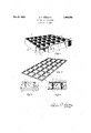
- Figure 1 is a perspective view, partly broken away, showing the container in which a liquid is adapted to be disposed. prior to solidification.
- Figure 2 is a perspective view of the cover or lid for the container shown in Fi re 1.
- igure 3 is a sectional view taken on .the line 33 of Figure 1 and showing one of the individual compartments containing an ice cube.
- Fi ure 4 is a view similar to Figure 3"? showing the liquid container in inverted position with the structure shown in Figure 2 I disposed beneath the container and alternperature increasing medium being applied to the walls of the individual compartments of the liquid container.
- my ice cube tray as comprisin a plurality of cups or containers 1, dispose therein in spaced relationshi
- the cups 1 are preferably disposed at uniform distances from each other, and are of the same general size and shape.
- the side walls 4 of these cups 1 converge, meeting a common base portion 5 at an an Ie, the purpose of which will be hereina ter described.
- each cup 1 is bounded on all sides by a portion containing slits or slots 2. These openings 2 are not restricted as to size, position, or number and may be disposed about the upper surface of the tray wherever desired.
- a skirt 3 Formed integrally with the outer edge of the upper's'urface of myice cube tray, and depending downwardly therefrom, is a skirt 3 which is capable of supporting the tray in an upright position. ,This sk1rt 3 is of sufficient height to extend below the bottoms of the cups 1 and support them in a supported position with relation to any object upon which the tray may rest while in an upright position. 1
- theskirt 3 tends to partiall confine the li uid within its limits and, ecause of its height, to cause the liquid to completely cover each cup.
- Y has the same dimensions as the upper surface of my ice cube tray, which I shall term a cover or lid.
- This member is capable of holding the ice cube tray when said ice cube tray is inverted thereon. It maybe used as a lid, if so desired, during a freezing operation.
- the cover as comprisin a plurality of shallow cups or containers 7 disposed therein in spaced relationship.
- the cups 7 are preferably of a relatively shallow nature, having the' same dimensions and are s aced uniformly within the cover.
- the si e wall 9 of each on 7 meets a common'base portion 10 at rlght angles.
- the width and breadth of this cup is aproximately the same as the width and readth of the cup 1 at its uppermost limits,
- each opening 8 is not restricted as to size, position or number and may be disposed about the upper surface of the cover wherever deslred. It is preferable that each opening 8 be of the same dimensions, and p aced so that when inverted on the ice cube tray, they will coincide with the openings 2 of that member.v However, they1 may be larger.
- eac of these two members maybe formed from one piece of material or if desired, may be assembled from individual parts.
- each individual cup 1 with the li uid to be solidified and place the tray in t e sleeve provided in the ordinary type of mechanical refrigerator.
- the cover may be placed thereon, if so desired.
- My ice cube tray is now inverted on the cover and I pour a warm hquld into the area surrounding the cups.
- the liquid drains off through the openings 8 and 2 which now coinclde forming a as'sageway through which a liquid may readily pass (Figure 4).
- the warm liquid raises the temperature of the sidewalls 4 of the cups 1 and thereby release the ice cubes iii-contact with the side walls causing them to drop into the cups 7 of the cover. It is apparent that no liquid other than that generated by the melting action of the ice in contact with the side walls has come into direct contact with the ice, this bein a preferred condition.
- the ice '11, w en it has broken contact with the walls of the cup 1 and has started to vmove downwardly, -will not ordinarily contact with the walls of the compartment thereafte because of the angle of said walls.
- ice cubes may be released from cells with so little resultant loss. It is within the broad aspect of my invention to accomplish this by merely providing an individual cell for each cube that may be completely covered by any warm liquid without contacting the liquid with the ice cube. A liquid may or may not be used to release the ice. Warm air may be directed upon the exterior of the cu'ps or they may be allowed to stand in a normal room temperature. It
- An ice cube tray comprising a plurality of cells, connecting portions between said cells, said connecting portions havi openings therein and the walls of said cel s being exteriorly spaced apart and a skirt for said tra r 2
- a tray having a lurality of cells therein, and a cover for sai tray said cover comprising indentations registering with said cells adapted to receive and retain the cubes when they are'emptied from the said tray, said indentations bein of substantially the same area as one end 0 said cubes.
- said cells being connected by perforated portions and the indented portions of said cover being separated by perforated ortions, the said indentations being adapted to coincide with said cells and the perforated portions vin the cover being adapted to coincide with the perforated connecting portions of the tray.
- a cover for a receptacle adapted to receive a liquid or a semi-solid material for the purpose of solidifying said material therein comprising a surface indented to signature.
- a cover for ice cube trays comprising a surface indented to receive and retain ice cubes in spaced relation when such cubes are emptied thereon from a tray, the indented portions of said surface. being of substantially the same area as one end of said cubes.
- a cover for ice cube trays comprising a surface indented to receive and retain ice cubes in spaced relation when such cubes are emptied thereon from a tray, the indentations in said cover being separated by perforated portions.
- An ice cube tray comprising a plurality of cells, connecting portlons between saidcells, said connecting ortions having openings therein, and a s 'rt for said tray de-.
Landscapes
- Engineering & Computer Science (AREA)
- Physics & Mathematics (AREA)
- Mechanical Engineering (AREA)
- Thermal Sciences (AREA)
- General Engineering & Computer Science (AREA)
Description
' ICE CUBE PAN STRUCTURE May 9, 1933.
Filed Oct. 8, 1928 INVENTOR.
Patented May 9, 1933 UNITED STATES PATENT OFFICE EDWIN P. COBIBEIT, O1 OOLUIBUSfOHIQ, ASSIaNOB OF ONE-FOURTH TO v\FIIILILK D- BELL, OF CQLUMBUS, OHIO ICE CUBE PAN STRUCTURE My invention relates to an ice cube pan structure. It pertains, particularly to a device in which water is adapted to be disposed preparatory to the formation of ice 5 cubes, although 1t is not limited thereto. For instance, the device might be employed with equal success in operations wherein liquids are solidified by other than a freez-l thereof ma 'be seen in the accompanyin in operation.
.n devices-of this type used at the present time, a shallow metal pan or tray is used in combination with a latticed or rid member adapted to be inserted into the pan or tra series of individual compartments. The latticed member is usually constructed of a plurality of metal strips that are assembled in such relation as to form the series'ofv individual compartments.
While my invent-ion ma be successfully used in the operation of so idifying various liquids, I have hereinafter described the invention as being particularlfy adapted to the formation of a plurality 0 ice cubes. My invention contemplates the provision of a 1i uid container so constructed that the ice on es may be removed from the individual compartments by the application of a temperature increasing agent to the walls of the cups instead of by direct contact between the temperature increasing agent and the ice cubes. q
My invention also contemplates the provision of a liquid containing device wherestructed that, on the application of a tem-' perature increasing medium to the walls of the individual compartments and the resultant loosening of the ice cubesin the compartments, the ice cubes will, in a minimum length of time, break contact with the walls of the compartments.
Further, my invention contemplates the provision of a second pan or tray which may take the form of a lid or cover for the first pan. This second tray is so constructed that, when it is placed over the container having the ice cubes therein, the entire device is inverted, and a temperature increas- 50 ing medium applied to the walls of the comother.
to divide. the interior thereof into a in the individual compartments are so conpartment in the original container, the ice cubes on droppin out of their respective compartments wil rest on the second lid or tray, preferably in spaced relation to each Numerous advantageous features and the objects of my invention maybe seen in the following description and one embodiment drawing w erein similar characters of re 0o erence designate corresponding parts and wherein:
Figure 1 is a perspective view, partly broken away, showing the container in which a liquid is adapted to be disposed. prior to solidification.
Figure 2 is a perspective view of the cover or lid for the container shown in Fi re 1.
igure 3 is a sectional view taken on .the line 33 of Figure 1 and showing one of the individual compartments containing an ice cube. I
Fi ure 4 is a view similar to Figure 3"? showing the liquid container in inverted position with the structure shown in Figure 2 I disposed beneath the container and alternperature increasing medium being applied to the walls of the individual compartments of the liquid container.
In the drawing, I have shown one embodiment of my ice cube tray as comprisin a plurality of cups or containers 1, dispose therein in spaced relationshi The cups 1 are preferably disposed at uniform distances from each other, and are of the same general size and shape. The side walls 4 of these cups 1 converge, meeting a common base portion 5 at an an Ie, the purpose of which will be hereina ter described. WM
It will be note'd' thateach cup 1 is bounded on all sides by a portion containing slits or slots 2. These openings 2 are not restricted as to size, position, or number and may be disposed about the upper surface of the tray wherever desired.
Formed integrally with the outer edge of the upper's'urface of myice cube tray, and depending downwardly therefrom, is a skirt 3 which is capable of supporting the tray in an upright position. ,This sk1rt 3 is of sufficient height to extend below the bottoms of the cups 1 and support them in a supported position with relation to any object upon which the tray may rest while in an upright position. 1
When In ice cube tray is inverted and a liquid applied thereto to'loosen the cubes, theskirt 3 tends to partiall confine the li uid within its limits and, ecause of its height, to cause the liquid to completely cover each cup.
I have shown in Figure 2 a member that Y has the same dimensions as the upper surface of my ice cube tray, which I shall term a cover or lid. This member is capable of holding the ice cube tray when said ice cube tray is inverted thereon. It maybe used as a lid, if so desired, during a freezing operation.
I have shown the cover as comprisin a plurality of shallow cups or containers 7 disposed therein in spaced relationship.
The cups 7 are preferably of a relatively shallow nature, having the' same dimensions and are s aced uniformly within the cover.
The si e wall 9 of each on 7 meets a common'base portion 10 at rlght angles. The width and breadth of this cup is aproximately the same as the width and readth of the cup 1 at its uppermost limits,
. and is adapted to coincide therewith when inverted thereon.
These cu s 7 are connected by portions provided wlth slots or slits 8. These openings 8 are not restricted as to size, position or number and may be disposed about the upper surface of the cover wherever deslred. It is preferable that each opening 8 be of the same dimensions, and p aced so that when inverted on the ice cube tray, they will coincide with the openings 2 of that member.v However, they1 may be larger.
It is apparent that eac of these two members maybe formed from one piece of material or if desired, may be assembled from individual parts.
In the use of my device, I fill each individual cup 1 with the li uid to be solidified and place the tray in t e sleeve provided in the ordinary type of mechanical refrigerator. The cover may be placed thereon, if so desired.
After the liquid is frozen I remove the tray and invert it on the lid as shown in Figure 4, or if the cover has been previously put in place, I simply invert the device as a whole while holding the cover in place.
It will be noted that the ice 11 (Figure 3) when frozen does not assume the shape of a true cube, but tapers slightly toward one 7 end.
My ice cube tray is now inverted on the cover and I pour a warm hquld into the area surrounding the cups. The liquid drains off through the openings 8 and 2 which now coinclde forming a as'sageway through which a liquid may readily pass (Figure 4).
The warm liquid raises the temperature of the sidewalls 4 of the cups 1 and thereby release the ice cubes iii-contact with the side walls causing them to drop into the cups 7 of the cover. It is apparent that no liquid other than that generated by the melting action of the ice in contact with the side walls has come into direct contact with the ice, this bein a preferred condition.
The ice '11, w en it has broken contact with the walls of the cup 1 and has started to vmove downwardly, -will not ordinarily contact with the walls of the compartment thereafte because of the angle of said walls.
The ic cube tray is now lifted from the su port and each individual cube is left in an upright position in a cup 7 of the cover. These cubes have not been materially reduced in size and the loss of solid is negligible.
I believe that I am the first to appreciate that these ice cubes may be released from cells with so little resultant loss. It is within the broad aspect of my invention to accomplish this by merely providing an individual cell for each cube that may be completely covered by any warm liquid without contacting the liquid with the ice cube. A liquid may or may not be used to release the ice. Warm air may be directed upon the exterior of the cu'ps or they may be allowed to stand in a normal room temperature. It
is understood that this may require a slight-' lybleonger period of time for releasing the cu Havingthus described my invention, what I claim is:
1. An ice cube tray comprising a plurality of cells, connecting portions between said cells, said connecting portions havi openings therein and the walls of said cel s being exteriorly spaced apart and a skirt for said tra r 2 In an ice cube tray structure, the combination of a tray having a lurality of cells therein, and a cover for sai tray, said cover comprising indentations registering with said cells adapted to receive and retain the cubes when they are'emptied from the said tray, said indentations bein of substantially the same area as one end 0 said cubes.
3. In an ice cube tray structure, the combination of a tra having a plurality of spaced cells therein, and a cover for said tray, said tray having a plurality of perforated connecting portions between the cells and said cover being constructed to permit, the passage of water through such 'perforaspaced cells therein, and a cover forsaid tray having a plurality of indentations therein,
said cells being connected by perforated portions and the indented portions of said cover being separated by perforated ortions, the said indentations being adapted to coincide with said cells and the perforated portions vin the cover being adapted to coincide with the perforated connecting portions of the tray.
5. A cover for a receptacle adapted to receive a liquid or a semi-solid material for the purpose of solidifying said material therein comprising a surface indented to signature.
receive and retain aritcles emptied there-' on when such articles are emptied thereon from a receptacle, the indentations in said cover being separated by. perforated portions.
6. A cover for ice cube trays comprising a surface indented to receive and retain ice cubes in spaced relation when such cubes are emptied thereon from a tray, the indented portions of said surface. being of substantially the same area as one end of said cubes.
7. A cover for ice cube trays comprising a surface indented to receive and retain ice cubes in spaced relation when such cubes are emptied thereon from a tray, the indentations in said cover being separated by perforated portions.
8. An ice cube tray comprising a plurality of cells, connecting portlons between saidcells, said connecting ortions having openings therein, and a s 'rt for said tray de-.
pending below the bases of said cells and elevatin said cells when said tray is resting on said s irt. In testimony whereof I hereby afiix my EDWIN P. CORBETT.
Priority Applications (1)
| Application Number | Priority Date | Filing Date | Title |
|---|---|---|---|
| US311109A US1908323A (en) | 1928-10-08 | 1928-10-08 | Ice cube pan structure |
Applications Claiming Priority (1)
| Application Number | Priority Date | Filing Date | Title |
|---|---|---|---|
| US311109A US1908323A (en) | 1928-10-08 | 1928-10-08 | Ice cube pan structure |
Publications (1)
| Publication Number | Publication Date |
|---|---|
| US1908323A true US1908323A (en) | 1933-05-09 |
Family
ID=23205447
Family Applications (1)
| Application Number | Title | Priority Date | Filing Date |
|---|---|---|---|
| US311109A Expired - Lifetime US1908323A (en) | 1928-10-08 | 1928-10-08 | Ice cube pan structure |
Country Status (1)
| Country | Link |
|---|---|
| US (1) | US1908323A (en) |
Cited By (4)
| Publication number | Priority date | Publication date | Assignee | Title |
|---|---|---|---|---|
| US2594127A (en) * | 1951-05-04 | 1952-04-22 | Raymond L Collier | Ice cube tray |
| US3778018A (en) * | 1971-07-22 | 1973-12-11 | Noel Y Co Ltd Sa Argentina De | Mold structure |
| US20090249805A1 (en) * | 2008-04-07 | 2009-10-08 | Holter Edward C | Ice Cube Tray and Method for Releasing a Single Cube from Tray |
| BE1026432B1 (en) * | 2019-01-03 | 2020-01-28 | Cruchten Guy Van | MOLD FOR VEGETABLE FATS AND THE USE THEREOF |
-
1928
- 1928-10-08 US US311109A patent/US1908323A/en not_active Expired - Lifetime
Cited By (6)
| Publication number | Priority date | Publication date | Assignee | Title |
|---|---|---|---|---|
| US2594127A (en) * | 1951-05-04 | 1952-04-22 | Raymond L Collier | Ice cube tray |
| US3778018A (en) * | 1971-07-22 | 1973-12-11 | Noel Y Co Ltd Sa Argentina De | Mold structure |
| US20090249805A1 (en) * | 2008-04-07 | 2009-10-08 | Holter Edward C | Ice Cube Tray and Method for Releasing a Single Cube from Tray |
| US8516835B2 (en) | 2008-04-07 | 2013-08-27 | Edward Carl Holter | Ice cube tray and method for releasing a single cube from tray |
| BE1026432B1 (en) * | 2019-01-03 | 2020-01-28 | Cruchten Guy Van | MOLD FOR VEGETABLE FATS AND THE USE THEREOF |
| WO2020141210A1 (en) | 2019-01-03 | 2020-07-09 | Van Cruchten Guy | Mould for vegetable fats and use of same |
Similar Documents
| Publication | Publication Date | Title |
|---|---|---|
| US2704928A (en) | Devices for use in the production of ice in refrigerators | |
| US4239175A (en) | Mold for forming frozen food product and cap member therefor | |
| US2166560A (en) | Freezing container for refrigerators | |
| US2732696A (en) | baker | |
| US3684235A (en) | Ice molding apparatus | |
| US2614399A (en) | Ice tray | |
| US1868503A (en) | Ice tray for mechanical refrigerators | |
| US6244065B1 (en) | Container and method for refrigerating a product | |
| US2961850A (en) | Individualized ice mold | |
| US2415451A (en) | Ice tray | |
| US1780980A (en) | Ice grid | |
| US2247018A (en) | Ice freezing mold | |
| US1908323A (en) | Ice cube pan structure | |
| US4023768A (en) | Ice cube mold | |
| US2496755A (en) | Frozen egg method and container | |
| US2011289A (en) | Ice cube tray | |
| US2498965A (en) | Ice tray | |
| US2498964A (en) | Ice tray | |
| US2087068A (en) | Ice cream cone | |
| US2063100A (en) | Grid used in connection with ice trays | |
| US1780422A (en) | Tray for refrigerating units | |
| US2266007A (en) | Ice tray | |
| US2104685A (en) | Storage milk cooler | |
| US2558984A (en) | Ice tray | |
| GB2113074A (en) | Container |