US1908321A - Arc lamp - Google Patents
Arc lamp Download PDFInfo
- Publication number
- US1908321A US1908321A US408087A US40808729A US1908321A US 1908321 A US1908321 A US 1908321A US 408087 A US408087 A US 408087A US 40808729 A US40808729 A US 40808729A US 1908321 A US1908321 A US 1908321A
- Authority
- US
- United States
- Prior art keywords
- carbon
- heat
- lamp
- economizing
- flame
- Prior art date
- Legal status (The legal status is an assumption and is not a legal conclusion. Google has not performed a legal analysis and makes no representation as to the accuracy of the status listed.)
- Expired - Lifetime
Links
- OKTJSMMVPCPJKN-UHFFFAOYSA-N Carbon Chemical compound [C] OKTJSMMVPCPJKN-UHFFFAOYSA-N 0.000 description 22
- 229910052799 carbon Inorganic materials 0.000 description 22
- 239000002184 metal Substances 0.000 description 17
- 229910052751 metal Inorganic materials 0.000 description 17
- 238000003475 lamination Methods 0.000 description 13
- 238000010438 heat treatment Methods 0.000 description 9
- XEEYBQQBJWHFJM-UHFFFAOYSA-N Iron Chemical compound [Fe] XEEYBQQBJWHFJM-UHFFFAOYSA-N 0.000 description 6
- 238000010276 construction Methods 0.000 description 6
- 238000001816 cooling Methods 0.000 description 4
- 230000000694 effects Effects 0.000 description 3
- 229910052742 iron Inorganic materials 0.000 description 3
- 239000002699 waste material Substances 0.000 description 3
- 230000006378 damage Effects 0.000 description 1
- 239000011810 insulating material Substances 0.000 description 1
- 230000007775 late Effects 0.000 description 1
- 230000004048 modification Effects 0.000 description 1
- 238000012986 modification Methods 0.000 description 1
- 230000005855 radiation Effects 0.000 description 1
Images
Classifications
-
- H—ELECTRICITY
- H05—ELECTRIC TECHNIQUES NOT OTHERWISE PROVIDED FOR
- H05B—ELECTRIC HEATING; ELECTRIC LIGHT SOURCES NOT OTHERWISE PROVIDED FOR; CIRCUIT ARRANGEMENTS FOR ELECTRIC LIGHT SOURCES, IN GENERAL
- H05B31/00—Electric arc lamps
- H05B31/0018—Electric arc lamps in a closed vessel
- H05B31/0021—Construction, in particular closure, of the vessel
Definitions
- My invention relates to improvements in are lamps, and more particularly in the economizing device provided for heating the crater of the carbons and for suitably reflecting the light rays. Economizing devices of this character have also been provided in flame arc lamps having an enclosed are.
- my invention consists in omitting the chamotte member of the device and providing in-lieu thereof a metal member having a high surface cooling and con structed for this purpose in the form of ribs or laminations, the ribs or other cooling members except the lowermost member being in heat transmitting contact with other parts of the lamps, and the lowermost ring or lamination being insulated from the other members and having he function of heating the cra er.
- the economizing device composed of ribs or laminations likewise has the property of heating the carbon to a certain extent. But it has no superlieating effect on the lowermost metal plate or lamination, because there is a comparatively high surface cooling by reason of the large surface of the device, and the device is in heat transmitting Contact with the other parts of the lamp and the outer sheet metal jacket enclosing the lamp. Since the metal has a high conductivity for heat the parts are cooled to a certain extent by their contact with the metal parts of the lamp.
- the lowermost lamination or the lowermost ring of the said economizing device constructed in the form of ribs or laminations is used for heating the crater, and therefore its temperature should be higher than that of the upper rings, for which purpose it is separated by insulating material from the other rings or laminations. 1 have found that in this construction in which instead of the chamotte member a cooling member of metal is provided heating is not such that it is necessary to depart from the preferred or reflector form of the economizing device. Therefore a good heating of the crater is combined with the reflector action.
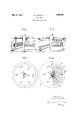
- Fig. 1 is an elevation partly in section showing a part of an arc lamp and the economizing device mounted thereon,
- Fig. 2 is a sectional plan view taken on the line 22 of Fig. 1,
- Fig. 3 is an elevation partly in section showing a modification
- Fig. 4 is a sectional plan view taken on the line 1-4 of Fig. 3.
- the reference character a indicates the upper carbon electrode which is mounted within a guide ring I).
- the economizing device 0 consists of a set of superposed transverse annular laminations which are connected with one another by metal rods d and screws.
- the said metal rods are in heat transmitting connection with the gearing and the outer sheet metal jacket of the are lam the rods (1 being extended u wardly and xed to the bottom plate h of t e said jacket by nuts 2', 2'.
- the individual laminations have received the characters 0 c, 0 c 0
- the lowermost lamination 0 is not in heat transmitting contact with the other laminations, and it is insulated therefrom by means of an insulating ring 6.
- the shape of the economizing device is such that the most effective reflection is obtained.
- the economizing device consists of sheet metal members in the form of radial ribs 0 mounted on an annular disk f connected with an annular disk 9 by bolts (P.
- the disk 9 is connected with the disk 0 by an insulating rin e.
- a metal plate k is welded whic is fixed to the bottom plate h of the jacket of the lamp by screws i thus transmitting the heat from the ribs to the jacket.
- a carboneconomizer for preventing waste of carbon and light rays by controlling the size, shape and seatin of the flame and focusing the light rays from the upper carbon below the lamp, comprising a member attached in heat transferring relation to the upper carbon near one end of the upper carbon and having aheat-radiating face configured for deflecting radiant heat back into the carbon crater to maintain the size, shape and seating of the flame constant and simultaneously
- a. plurality of heat radiating members said heat radiating members being connected together in heat transferring relation to the carbon by means which connect them in heat transferring relation to said fiame-enclosing frame and being heatinsulated from said first member.
- a carbon-economizer for preventing waste of carbon and light rays by controlling the size, shape and seating of the flame and focusing the light rays from the upper carbon below the lamp, comprising a downwardly opening hemlspherical metal plate attached in heat transferring relation to the upper carbon near the crater end thereof, a similar plate attached in heat transferring relation to said carbon above said first plate and concentric therewith, a heat insulating member disposed between the two plates, and a plurality of conical, downwardly opening disks supported on said second plate transversely of the carbon and heat connected to said carbon, said disks constituting laminations of the economizer, the laminations being connected to the enclosing frame by heat conducting members.
- a carbon-economizer for reventin waste of carbon and light rays or controIling the size, shape and seating of the flame and focusing the light rays from the upper carbon below the lamp comprising a downwardly opening hemispherical metal plate attached in heat transferring relation to the upper carbon near the crater end thereof, a similar plate attached in heat transferring relation to said carbon above said first plate and concentric therewith, a heat insulating member disposed between the two plates, a downwardly opening conical member supported on said second plate, a plurality of heat radiating metal ribs arranged radially of said carbon on said conical member, said radial ribs being heat connected at their inner ends to said carbon and at their tops to said enclosing frame.
Landscapes
- Arrangement Of Elements, Cooling, Sealing, Or The Like Of Lighting Devices (AREA)
Description
May 9, 1933.
0. CONRADTY ARC LAMP Filed Nov. 18, 1929 Inventor;
Patented May 9, 1933 PATENT @FFICE OTTMAB CONRADTY, OF I IUBEMBERG, GEBMANY ABC LAMP Application filed November 18, 1929, Serial No. 408,037, and. in Germany November 24, 1928.
My invention relates to improvements in are lamps, and more particularly in the economizing device provided for heating the crater of the carbons and for suitably reflecting the light rays. Economizing devices of this character have also been provided in flame arc lamps having an enclosed are.
In constructions now in use the luminous effect of flame arc lamps having an enclosed are for excluding the air depends on the construction of the economizing device surrounding the upper carbon downwardly nearly to the lower luminous cone. Ordinarily economizing devices for flame arc lamps are constructed so that the upper part is provided by a member of chamotte, which member of chamotte has been used ever since the first construction of arc lamps, while below the said chamotte member a metal plate was provided for properly heating the crater of the arc. Economizing devices of this type and the combination of chamotte and iron members are objectionable for the reason that the upper member of chamotte which has a low conductivity for heat is heated so far that it acts as a mufiie furnace,
and that therefore the metal plate provided below the same is'superheated to such an extent that the upper carbon is subject to destruction and breaking, and that other drawbacks prevail. For this reason tne economizing member comprising an iron plate has been constructed so that the excessive heating was prevented, for which purpose a lower iron plate has been provided which was hori zontal or which was even conical and bent outwardly. However, this construction is objectionable because thereby correct reflection and concentration of the radiation is impossible, so that much light is wasted by throwing the light rays in lateral or upward direction.
.rect shape of the device suitable for reflection to plane or conical form. With this object in view my invention consists in omitting the chamotte member of the device and providing in-lieu thereof a metal member having a high surface cooling and con structed for this purpose in the form of ribs or laminations, the ribs or other cooling members except the lowermost member being in heat transmitting contact with other parts of the lamps, and the lowermost ring or lamination being insulated from the other members and having he function of heating the cra er. Thereby the drawbacks of the chamotte economizing member are obviated, and more particularly the property of the said economizing device acting as a mufile furnace and having excessive heating effect. The economizing device composed of ribs or laminations likewise has the property of heating the carbon to a certain extent. But it has no superlieating effect on the lowermost metal plate or lamination, because there is a comparatively high surface cooling by reason of the large surface of the device, and the device is in heat transmitting Contact with the other parts of the lamp and the outer sheet metal jacket enclosing the lamp. Since the metal has a high conductivity for heat the parts are cooled to a certain extent by their contact with the metal parts of the lamp. The lowermost lamination or the lowermost ring of the said economizing device constructed in the form of ribs or laminations is used for heating the crater, and therefore its temperature should be higher than that of the upper rings, for which purpose it is separated by insulating material from the other rings or laminations. 1 have found that in this construction in which instead of the chamotte member a cooling member of metal is provided heating is not such that it is necessary to depart from the preferred or reflector form of the economizing device. Therefore a good heating of the crater is combined with the reflector action.
In order that my invention be more clearly understood two examples embodying the same have been shown in the accompanying drawing in which the same letters of reference have been used in all the views to indicate corresponding parts.
Fig. 1 is an elevation partly in section showing a part of an arc lamp and the economizing device mounted thereon,
Fig. 2 is a sectional plan view taken on the line 22 of Fig. 1,
Fig. 3 is an elevation partly in section showing a modification, and
Fig. 4 is a sectional plan view taken on the line 1-4 of Fig. 3.
In Figs. 1 and 2 the reference character a indicates the upper carbon electrode which is mounted within a guide ring I). The economizing device 0 consists of a set of superposed transverse annular laminations which are connected with one another by metal rods d and screws. The said metal rods are in heat transmitting connection with the gearing and the outer sheet metal jacket of the are lam the rods (1 being extended u wardly and xed to the bottom plate h of t e said jacket by nuts 2', 2'. In Fig. 1 the individual laminations have received the characters 0 c, 0 c 0 The lowermost lamination 0 is not in heat transmitting contact with the other laminations, and it is insulated therefrom by means of an insulating ring 6. The shape of the economizing device is such that the most effective reflection is obtained.
In themodification shown in Figs. 3 and 4 the economizing device consists of sheet metal members in the form of radial ribs 0 mounted on an annular disk f connected with an annular disk 9 by bolts (P. The disk 9 is connected with the disk 0 by an insulating rin e. To the to s of the ribs 0 a metal plate k is welded whic is fixed to the bottom plate h of the jacket of the lamp by screws i thus transmitting the heat from the ribs to the jacket.
I wish it to be understood that the constructions of the economizing device shown in the figures are merely examples, and that other forms ma be used, such for example as corrugated sfieet metal lates. Further, I wish it to be understood t at I do not limit myself to are lamps with enclosed arc, and that the improved economizing device may be used in arc lamps of any type.
I claim:
1. In an enclosed-flame arc lamp for continuous lighting, including a flame-enclosing frame, and carbons therein, a carboneconomizer for preventing waste of carbon and light rays by controlling the size, shape and seatin of the flame and focusing the light rays from the upper carbon below the lamp, comprising a member attached in heat transferring relation to the upper carbon near one end of the upper carbon and having aheat-radiating face configured for deflecting radiant heat back into the carbon crater to maintain the size, shape and seating of the flame constant and simultaneously In said drawreflecting and focusing the light rays below the lamp, a. plurality of heat radiating members, said heat radiating members being connected together in heat transferring relation to the carbon by means which connect them in heat transferring relation to said fiame-enclosing frame and being heatinsulated from said first member.
2. In an enclosed-flame arc lamp for continuous lighting, including a flame-enclosing frame, and carbons therein, a carbon-economizer for preventing waste of carbon and light rays by controlling the size, shape and seating of the flame and focusing the light rays from the upper carbon below the lamp, comprising a downwardly opening hemlspherical metal plate attached in heat transferring relation to the upper carbon near the crater end thereof, a similar plate attached in heat transferring relation to said carbon above said first plate and concentric therewith, a heat insulating member disposed between the two plates, and a plurality of conical, downwardly opening disks supported on said second plate transversely of the carbon and heat connected to said carbon, said disks constituting laminations of the economizer, the laminations being connected to the enclosing frame by heat conducting members.
3. In an enclosed-flame arc lamp for continuous lighting, including a flame-enclosing frame, and carbons therein, a carbon-economizer for reventin waste of carbon and light rays or controIling the size, shape and seating of the flame and focusing the light rays from the upper carbon below the lamp, comprising a downwardly opening hemispherical metal plate attached in heat transferring relation to the upper carbon near the crater end thereof, a similar plate attached in heat transferring relation to said carbon above said first plate and concentric therewith, a heat insulating member disposed between the two plates, a downwardly opening conical member supported on said second plate, a plurality of heat radiating metal ribs arranged radially of said carbon on said conical member, said radial ribs being heat connected at their inner ends to said carbon and at their tops to said enclosing frame.
OTTMAR CONRADTY.
Applications Claiming Priority (1)
| Application Number | Priority Date | Filing Date | Title |
|---|---|---|---|
| DE1908321X | 1928-11-24 |
Publications (1)
| Publication Number | Publication Date |
|---|---|
| US1908321A true US1908321A (en) | 1933-05-09 |
Family
ID=7748765
Family Applications (1)
| Application Number | Title | Priority Date | Filing Date |
|---|---|---|---|
| US408087A Expired - Lifetime US1908321A (en) | 1928-11-24 | 1929-11-18 | Arc lamp |
Country Status (1)
| Country | Link |
|---|---|
| US (1) | US1908321A (en) |
Cited By (1)
| Publication number | Priority date | Publication date | Assignee | Title |
|---|---|---|---|---|
| FR2307433A1 (en) * | 1975-04-07 | 1976-11-05 | Varian Associates | MOBILE ELECTRODE ARC LAMP |
-
1929
- 1929-11-18 US US408087A patent/US1908321A/en not_active Expired - Lifetime
Cited By (1)
| Publication number | Priority date | Publication date | Assignee | Title |
|---|---|---|---|---|
| FR2307433A1 (en) * | 1975-04-07 | 1976-11-05 | Varian Associates | MOBILE ELECTRODE ARC LAMP |
Similar Documents
| Publication | Publication Date | Title |
|---|---|---|
| US2878371A (en) | Light shade | |
| US1804049A (en) | Electric lamp | |
| US1908321A (en) | Arc lamp | |
| US2091905A (en) | Electric resistance heating element | |
| US2072205A (en) | Combined light and heat radiator with reflector for medical purposes | |
| US2084999A (en) | Electric lamp | |
| US2244045A (en) | Ceramic burner unit for broilers | |
| US2231236A (en) | Heating means | |
| US2470715A (en) | Electric heating unit | |
| US2214503A (en) | Gas heating apparatus | |
| US808086A (en) | Thermo-electric battery. | |
| US2269337A (en) | Thermoelectric generator and burner therefor | |
| US2441672A (en) | Thermopile for furnace control | |
| US2062466A (en) | Convection type electric radiator | |
| US2030820A (en) | Electric heater | |
| US10921022B2 (en) | Heating device | |
| US2126650A (en) | Lighting device | |
| US3025424A (en) | Electric lamp | |
| US1694067A (en) | Therapeutic lamp | |
| US1714242A (en) | Reflector arc | |
| US445379A (en) | peral | |
| JPS60182654A (en) | Light illumination device | |
| US1581357A (en) | Arc lamp, electrode unit for the same and method of producing light | |
| US2261533A (en) | Electric heating device | |
| US1604134A (en) | Moving-picture lamp |