US1908309A - Brake apparatus - Google Patents
Brake apparatus Download PDFInfo
- Publication number
- US1908309A US1908309A US498320A US49832030A US1908309A US 1908309 A US1908309 A US 1908309A US 498320 A US498320 A US 498320A US 49832030 A US49832030 A US 49832030A US 1908309 A US1908309 A US 1908309A
- Authority
- US
- United States
- Prior art keywords
- trailer
- truck
- vacuum
- booster
- brakes
- Prior art date
- Legal status (The legal status is an assumption and is not a legal conclusion. Google has not performed a legal analysis and makes no representation as to the accuracy of the status listed.)
- Expired - Lifetime
Links
- 230000008878 coupling Effects 0.000 description 24
- 238000010168 coupling process Methods 0.000 description 24
- 238000005859 coupling reaction Methods 0.000 description 24
- 230000007246 mechanism Effects 0.000 description 20
- 239000012530 fluid Substances 0.000 description 3
- 239000007788 liquid Substances 0.000 description 3
- CVSVTCORWBXHQV-UHFFFAOYSA-N creatine Chemical compound NC(=[NH2+])N(C)CC([O-])=O CVSVTCORWBXHQV-UHFFFAOYSA-N 0.000 description 2
- 230000000694 effects Effects 0.000 description 2
- WXAYTPABEADAAB-UHFFFAOYSA-N Oxyphencyclimine hydrochloride Chemical compound Cl.CN1CCCN=C1COC(=O)C(O)(C=1C=CC=CC=1)C1CCCCC1 WXAYTPABEADAAB-UHFFFAOYSA-N 0.000 description 1
- 235000014443 Pyrus communis Nutrition 0.000 description 1
- 238000012986 modification Methods 0.000 description 1
- 230000004048 modification Effects 0.000 description 1
Images


Classifications
-
- B—PERFORMING OPERATIONS; TRANSPORTING
- B60—VEHICLES IN GENERAL
- B60T—VEHICLE BRAKE CONTROL SYSTEMS OR PARTS THEREOF; BRAKE CONTROL SYSTEMS OR PARTS THEREOF, IN GENERAL; ARRANGEMENT OF BRAKING ELEMENTS ON VEHICLES IN GENERAL; PORTABLE DEVICES FOR PREVENTING UNWANTED MOVEMENT OF VEHICLES; VEHICLE MODIFICATIONS TO FACILITATE COOLING OF BRAKES
- B60T13/00—Transmitting braking action from initiating means to ultimate brake actuator with power assistance or drive; Brake systems incorporating such transmitting means, e.g. air-pressure brake systems
- B60T13/10—Transmitting braking action from initiating means to ultimate brake actuator with power assistance or drive; Brake systems incorporating such transmitting means, e.g. air-pressure brake systems with fluid assistance, drive, or release
- B60T13/58—Combined or convertible systems
- B60T13/581—Combined or convertible systems both hydraulic and pneumatic
Definitions
- My invention relates to brake apparatus and more particularly to brake apparatus for use with trucks and semi-trailers.
- a master cylinder of well known type is usually mounted on the semi-trailer and operated by the manual lever in the drivers cab of the tractor.
- My invention relates to' such semitrailers using hydraulic brakes .and to improvements therein.
- Another object of my invention is to provide means for utilizing the movement of the coupler lever to connect the hydraulic brakes of a semi-trailer in series operation with the brakes of the tractor.
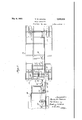
- FIG. 1 is a fragmentary diagrammatic side elevation of a truck-tractor and semi-trailer employing the braking system of my invention
- Fig. 2 is another fragmentary, somewhat diagrammatic, view of the truck-tractor and semi-trailer illustrated in Fig. 1', illustrating the application of the braking system of my invention
- Fig. 3 is an. enlarged diagrammatic plan view of a truck and semi-trailer, illustrating the braking system of my invention.
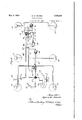
- Fig. 4 is a schematic layout ofthe parts of the braking system of my invention shown applied to a truck and fifth wheel semitrailer.
- the braking system applied to the tractor 10 in the drawings is of the h draulic type and one wherein a master cylindbr or pump 12 containing the braking fluid or liquid is connected by a series of conduits with wheel cylinders 13 which are adapted to receive the liquid pressure from the master cylinder and o erate the brakes at each wheel.
- a brake pe al 14 suitably mounted in the operators cab of the tractor, is connected with the master cylinder 12 by means of a rod 15 and movement of the brake pedal will operate a plunger within the master cylinder and force liquid under pressure to the Wheel cylinders 13 to apply the brakes.
- a vacuum booster 16 of any well-known type comprising an enlarged diameter piston adapted to be moved by a vacuum created in the intake manifold 18 of an automotive I engine 19, is suitably mounted by a bracket 20 to the chassis of the tractor 10.
- the vacuum booster is connected with the intake manifold 18 of the engine 19 by a vacuum tube or pipe 17 which is suitably connected in a leakproof manner at one end with the vacuum booster 16 and at the other end with the intake manifold 18 of the automotive engine 19, as best shown in Fig. 4.
- a valve housing 21 is disposed within the vacuum supply line 17 between the vacuum booster and the intake manifold.-
- the brake rod 15 which operates the master cylinder pump 12 to generate the fluid pressure for operating the brakes 13 passes through the valve housing 21 and acts as a valve to shut suction of the intake manifold 18 of the engine 19 to operate the vacuum booster 16.
- the booster is connected with the master cylinder 12 by a rod 23 which is in alignment with or a continuation of the brake rod 15.
- a rod 23 which is in alignment with or a continuation of the brake rod 15.
- the trailer 11 has a master supply cylinder and pump 30 mounted thereon in a suitable manner and connected with suitable conduits to the wheel cylinders 31 of the brakes of the trailer so that operation of the pump will generate fluid pressure to actuate the brakes 31.
- brake rod 32 connects the master cylinder pump 30 with a bell crank lever 33 pivotally mounted at 33' in a suitable manner in the forward end of the semi-trailer.
- the bell crank lever extends towards the forward end of the trailer and forms a brake cam lever 34.
- the rear end of the trucktractor is provided with a fifth wheel track 35 of any suitable type well known in the art which is adapted to engage the rollers or wheels of the front end of the semi-trailer during coupling operation.
- a king-pin 36 is suitably mounted on the truck-tractor in the center of the fifth wheel track.
- a pair of mechanical jaws 37 are mounted in a suitable manner at the front end of the trailer. Coupling of the trailer and truck-tractor is effected by backing the tractor into the trailer so that the front end of the trailer engages the fifth wheel track, overriding the track and rear end of the trucktrailer until the mechanical jaws 37 engage the king-pin 36.
- a locking member 38 is suitably mounted in the fifth wheel coupling mechanism and is connected with an operating lever 39 located in the drivers cab by means of a coupling rod 40.
- this semi-trailer overrides the fifth wheel track of the tractor and the jaws 37 of the trailer have engaged the king-pin 36 of the tractor, the driver may operate the lever 39 which will reciprocate the cou ling rod 40 and move the locking member 8 to clasp the jaws about the king-pin and complete the coupling of the trailer and the truck.
- Such a fifth wheel coupling connection may be of any well-known type, the one illustrated in the drawings and described herein being conventional.
- a brake push pin 41 is suitably mounted in a bore in the center of the king-pin 36 and is adapted to be reciprocated vertically.
- a head 42 is formed thereon which projects above the top of the king-pin and seats thereon when the brake push pin is in lowered position.
- the brake cam lever 34 formed on the bell crank lever 33 of the semi-trailer is adapted to override the brake push pin 41 disposed within the center of the king-pin 36 as the trailer overrides the tractor.
- One arm of the bell crank lever 52 is in alignment and con-- tact with the lower end of the brake push pin 41 underneath the king-pin 3.6 and forms a cam 54 for engagingthe push pin.
- the bell crank lever 52 is suitably connected with the vacuum booster 50 by means of a brake rod 55 so that movement of the piston of the vacuum booster 50 will rotate the bell crank lever 52 upon the pivot'53 and raise the cam arm 54 which is in contact with the lower end of the brake push pin 41.
- the vacuum booster cylinder is connected with the intake manifold 18 of the automotive engine 19 by means of the vacuum supply line 17.
- a mechanical valve 57 is disposed between the vacuum booster 50 and the vacuum booster 16 in asmanner whereby the valve 57 may cut off the vacuum booster 50 so that the truck unit or vacuum booster 16 will operate independently of the secondary booster 50.
- the valve 57 is rotated to connect the vacuum supply line 17 with the intake manifold 18 and booster 50 the secondary booster 50 will thereupon be in series connection, so to speak, with the truck-tractor booster 16 and will operate simultaneously therewith.
- a valve actuating member 60 is suitably secured to the coupling rod and is adapted to engage a valve arm 61 which extends from the valve 57.
- the valve actuating member 60 is so disposed on the coupling rod 40 in engagement with the valve arm 61 sothat the valve 57 is in shut off position when the coupling rod 40'is released and the trucktractor disconnected and free from the semitrailerwith the operating lever 39 in a forward position, as illustrated in Figs. 1 and 4 of the drawings.
- the truck unit of my braking system comprising the master cylinder and pump 12 and vacuum booster 16 for operating the brakes 13 of the truck, will operate independently and not afiect the secondary vacuum booster unit. Such will be the condition which exists when the truck is disconnected from the trailer.
- the truck is connected with the trailer by the usual coupling means the jaws 37 will surround the king-pin 36 and the driver will 'draw back the lever 39, recipnocating the operating rod 40 and actuating the locking member 38, and lock the semi-trailer into operating engagement with the truck.
- I brake cam lever 34 will override the head 42 to connect the trailer braking system with the truck braking system.
- the vacuum booster 16 will be operated by the intake'manifold 18 to assist in applying the brakes 13 of the truck, and the vacuum booster 50 of the trailer unit will rotate the bell crank lever 52, raising the brake push pin 41 which, in turn, rotates the bell crank lever 33, reciprocating the brake rod 32 of the trailer unit to operate the master pump cylinder 30 mounted on the semi-trailer which will actuate the brakes 31 of the semi-trailer.
- the movement of the foot pedal 14 will operate all six brakes of the connected truck and semi-trailer units.
- a brake mechanism therefor comprising brakes on the trailer, hydraulic mechanism on said trailer for operating said brakes, a vacuum operated piston on said truck, coupling means for said truck and trailer, operably connected means between said piston and said hydraulic mechanism when said truck and trailer are coupled, a vacuum conduit for conducting air from one side of said vacuum piston to actuate the same, a shut-off valve in said conduit, locking means for said coupling means, and means for simultaneously actuating said locking means and opening said valve.
- a brake mechanism therefor comprising brakes on the trailer, a vacuum booster on the truck, operably connecting means between the booster and said brakes, means for locking said truck to said trailer, vacuum creating means communicating with said booster,
- valve means for shutting off communication between the vacuum creating means and the booster, and a manually operable lever operably connected to both said valve and said locking means to actuate the same simultaneously.
- a brake mechanism therefor comprising brakes on the trailer, a vacuum booster on the truck,
- M the trailer, hydraulic mechanism on said trailer for operating said brakes, a vacuum operated piston on said truck, coupling means forsaid truck and trailer, operably connected means between said piston and said bydraulic mechanism when said truck and trailer are coupled, a vacuum conduit for conducting air from one side of said vacuum piston to actuate the same, a shut-ofi' valve in said conduit, locking means for said coupling means, and a manually operable lever operably connectedto both said valve and said locking means to actuate the same simultaneously.
- a brake mechanism therefor comprising brakes on the trailer, hydraulic mechanism on said trailer for operating said brakes, a vacuum I operated piston on said truck, coupling means for said truck and trailer, operably connected means between said piston and said hydraulic mechanism when said truck and trailer are coupled, a vacuum conduit for conducting air from one side of said vacuum piston to actuate the same, a shut-off valve in said conduit, locking means for said coupling means, and a reciprocable rod operably connected with said valve and said locking means, and adapted to actuate the same to lock the truck to the trailer and open said valve during the movement of said rod in one direction.
- a brake mechanism therefor comprising brakes on the trailer, a vacuum booster on the truck, operable connecting means between the booster and said brakes when the truck and trailer are coupled.
- a truck a trailer, brakes on said truck and on said trailer, independent hydraulic means for actuating the brakes on the truck and on the trailers
- vacuum mechanism on said truck including a booster operably connected with the hydraulic means on the truck to actuate the same, a second booster on said truck operably connectedwith the hydraulic means on the trailer to actuate the same, means for creating a vacuum in said vacuum mechanism, means for controllably closing communication between said vacuum creating means and both of said boosters, a shut off valve for closing communication between said vacuum creating means and said second booster, means for locking said trailer to said true: and means for simultaneously actuating said locking means and said shut off valve.
- shut-off valve between said vacuum creating means and said second booster, and means for simultaneously actuating said locking means and opening said shut-ofi valve.
- a device of the class described in combination a truck, a trailer, brakes on said truck and on said trailer, independent hydraulic means for actuating the brakes on the truck and on the trailers, vacuum mechanism on said truck includin a booster operably connected with the hy raulic means on the truck to actuate the same, a second booster on said truck operably connected with the hydraulic means on the trailer to actuate the same, means for creating a vacuum in said vacuum mechanism, means for controllably closing communication between said vacuum creatin means and both of said boosters, means or looking said trailer to said truck,
- shut-oil valve between said vacuum creating means and said second booster, and a manually operable lever operably connected to both said valve and said locking means to actuate 5 the same simultaneously.
- vacuum mechanism on said truck including a booster 0perably connected with the hydraulic means on the truck to actuate the same, a second booster on said truck operably connected with the hydraulic means on the trailer to actuate the same, means for creating a vacuum, in said vacuum mechanism, means for controllably closing communication between said vacuum creating means and both of said boosters, means for locking said trailer to said truck, a shut-off valve between said vacuum creating means and said second booster and a reciprocable rod operably connected with said valve and said locking means, and
Landscapes
- Engineering & Computer Science (AREA)
- Transportation (AREA)
- Mechanical Engineering (AREA)
- Regulating Braking Force (AREA)
Description
M. w. BOWEN BRAKE APPARATUS Filed Nov. 26, 1950 4 S eets-Sheet 1 May 9, 1933.
y 1933- M. w. BOWEN 1,908,309
I BRAKE APPARATUS Filed Nov. 26, 1930 4 heets-Sheet 2 y 9, 1933. M. w; BOWEN 1,908,309
BRAKE APPARATUS Filed Nov. 26, 1930 4 Sheeis-Sheet 3 May 9, 1933. M, w. BOWEN 1,908,309
BRAKE APPARATUS Filed Nov. 26, 1950 4 Sheets-Sheet 4 w ap 7M.
Patented May 9, 1933 UNITED STATES, PATENT OFFICE mON W. BOWEN, OF DETROIT, MICHIGAN, ASSIGNOR '10 HYDRAULIC BRAKE comm, 015 DETROIT, MICHIGAN, A CORPORATION OF CALIFORNIA ,IBRAKE APPARATUS Application filed November 26, 1930. Serial No. 498,320.
My invention relates to brake apparatus and more particularly to brake apparatus for use with trucks and semi-trailers.
It is a well-known practice to use, especial- 6 ly in automotive hauling, a. truck which acts as a tractor and which is designed to be en-.
gaged with a semi-trailer or groups of semitrailers. In this practice the truck-tractor is engaged with the semi-trailer in an automatic manner through means of a fifth wheel by which the semi-trailer is pivotally connectedwith the tractor. The rear wheels of the semi-trailer are provided with brakes similar to those on the truck-tractor and are v 16 usually controlled by a handlever in the drivers cab through suitable linkage passing through the center of the king-pin which connects the fifth wheel of the semi-trailer and tractor. It is also the practice to provide a secondary coupler lever for effecting the looking of the fifth wheel and tractor from the drivers cab. In such semi-trailer apparatus,
in which hydraulic brakes are used, a master cylinder of well known type is usually mounted on the semi-trailer and operated by the manual lever in the drivers cab of the tractor. My invention relates to' such semitrailers using hydraulic brakes .and to improvements therein.
It is an object of my invention to provide an improved means of operating the brakes of a semi-trailer.
I It is an object of my invention to provide an improved means of operating the hydraulic brakes of a semi-trailer.
Another object of my invention is to provide means for utilizing the movement of the coupler lever to connect the hydraulic brakes of a semi-trailer in series operation with the brakes of the tractor.
It is another object of my invention to provide a vacuum booster for operating the brakes of the semi-trailer.
It isstill another object of my invention to provide a vacuum booster for operating the brakes of the tractor, together with a second vacuum booster for operating the brakes of the semi-trailer, and valve means operated by the coupling lever to connectthe two boosters.
It is a further object of my invention to provide vacuu-m boosted brake operating means for semi-trailers which may automatically be associated with anddisconnected from the vacuum boosting means of the tractor bythe same lever which effects the coupling and uncoupling of'the semi-trailer.
Further objects and advantages will ap- 1 pear from the following detailed description and accompanyingdrawings, in which Fig. 1 is a fragmentary diagrammatic side elevation of a truck-tractor and semi-trailer employing the braking system of my invention;
Fig. 2 is another fragmentary, somewhat diagrammatic, view of the truck-tractor and semi-trailer illustrated in Fig. 1', illustrating the application of the braking system of my invention;
Fig. 3 is an. enlarged diagrammatic plan view of a truck and semi-trailer, illustrating the braking system of my invention; and
Fig. 4 is a schematic layout ofthe parts of the braking system of my invention shown applied to a truck and fifth wheel semitrailer.
Referring to the drawings, in which like numerals designate like parts throughout the several views, I have shown in Fig. 1 a trucktractor 10 of any well-known design which is for use with a semi-trailer-ll. The braking system applied to the tractor 10 in the drawings is of the h draulic type and one wherein a master cylindbr or pump 12 containing the braking fluid or liquid is connected by a series of conduits with wheel cylinders 13 which are adapted to receive the liquid pressure from the master cylinder and o erate the brakes at each wheel. A brake pe al 14, suitably mounted in the operators cab of the tractor, is connected with the master cylinder 12 by means of a rod 15 and movement of the brake pedal will operate a plunger within the master cylinder and force liquid under pressure to the Wheel cylinders 13 to apply the brakes. w
A vacuum booster 16 of any well-known type comprising an enlarged diameter piston adapted to be moved by a vacuum created in the intake manifold 18 of an automotive I engine 19, is suitably mounted by a bracket 20 to the chassis of the tractor 10. The vacuum booster is connected with the intake manifold 18 of the engine 19 by a vacuum tube or pipe 17 which is suitably connected in a leakproof manner at one end with the vacuum booster 16 and at the other end with the intake manifold 18 of the automotive engine 19, as best shown in Fig. 4.
A valve housing 21 is disposed within the vacuum supply line 17 between the vacuum booster and the intake manifold.- The brake rod 15 which operates the master cylinder pump 12 to generate the fluid pressure for operating the brakes 13 passes through the valve housing 21 and acts as a valve to shut suction of the intake manifold 18 of the engine 19 to operate the vacuum booster 16.
The booster is connected with the master cylinder 12 by a rod 23 which is in alignment with or a continuation of the brake rod 15. Thus the suction created by the intake manir fold greatly increases the force applied to the master cylinder 12 to set the brakes 13 of the automotive vehicle. Such a hydraulic Vacuum boosted braking system is well known in the art and is used particularly with heavy commercial automotive vehicles such as trucks and truck-tractors illustrated in the drawings. A movement of the foot lever 14 operates the hydraulic braking system assisted by the power generated in the vacuum booster when thrown into operative connection with the intake manifold of the engine.
All of the above description is conventional and my invention has particularly to do with such a vacuum boosted system when applied to a truck-tractor for use withsemi-trailers and particularly with improvements therein and application of vacuum boosted brake powerto the brakes of the trailer.
The trailer 11 has a master supply cylinder and pump 30 mounted thereon in a suitable manner and connected with suitable conduits to the wheel cylinders 31 of the brakes of the trailer so that operation of the pump will generate fluid pressure to actuate the brakes 31.
A, brake rod 32 connects the master cylinder pump 30 with a bell crank lever 33 pivotally mounted at 33' in a suitable manner in the forward end of the semi-trailer. The bell crank lever. extends towards the forward end of the trailer and forms a brake cam lever 34. ,The rear end of the trucktractor is provided with a fifth wheel track 35 of any suitable type well known in the art which is adapted to engage the rollers or wheels of the front end of the semi-trailer during coupling operation.
A king-pin 36 is suitably mounted on the truck-tractor in the center of the fifth wheel track. A pair of mechanical jaws 37 are mounted in a suitable manner at the front end of the trailer. Coupling of the trailer and truck-tractor is effected by backing the tractor into the trailer so that the front end of the trailer engages the fifth wheel track, overriding the track and rear end of the trucktrailer until the mechanical jaws 37 engage the king-pin 36. A locking member 38 is suitably mounted in the fifth wheel coupling mechanism and is connected with an operating lever 39 located in the drivers cab by means of a coupling rod 40. Thus when the front end of this semi-trailer overrides the fifth wheel track of the tractor and the jaws 37 of the trailer have engaged the king-pin 36 of the tractor, the driver may operate the lever 39 which will reciprocate the cou ling rod 40 and move the locking member 8 to clasp the jaws about the king-pin and complete the coupling of the trailer and the truck.
Such a fifth wheel coupling connection may be of any well-known type, the one illustrated in the drawings and described herein being conventional.
A brake push pin 41 is suitably mounted in a bore in the center of the king-pin 36 and is adapted to be reciprocated vertically. A head 42 is formed thereon which projects above the top of the king-pin and seats thereon when the brake push pin is in lowered position. It will be noted, in Figs. 1 and 4 particularly, that the brake cam lever 34 formed on the bell crank lever 33 of the semi-trailer is adapted to override the brake push pin 41 disposed within the center of the king-pin 36 as the trailer overrides the tractor. I
It will thus be noted that an upward move-' ment of the brake push pin, when the semitrailer and tractor have been coupled together, will raise the brake cam lever 34, rotate the bell crank lever 33, and reciprocate the brake rod 32 to operate the master pump 30 and apply the brakes 31 of the semitrailer. In the past the brake push pin has been operated by manual means through a separate brake lever in the drivers cab and proper mechanical linkage. To accomplish this result I provide a secondary vacuum booster pump 50 which is suitably mounted on the chassis 10 of the automotive truck by means of a bracket 51. A bell crank lever 52 1s proylded for operating the brake push pin andls pivotally mounted on the trucktractor 10 on a pivot 53. One arm of the bell crank lever 52 is in alignment and con-- tact with the lower end of the brake push pin 41 underneath the king-pin 3.6 and forms a cam 54 for engagingthe push pin. The bell crank lever 52 is suitably connected with the vacuum booster 50 by means of a brake rod 55 so that movement of the piston of the vacuum booster 50 will rotate the bell crank lever 52 upon the pivot'53 and raise the cam arm 54 which is in contact with the lower end of the brake push pin 41.
The vacuum booster cylinder is connected with the intake manifold 18 of the automotive engine 19 by means of the vacuum supply line 17. A mechanical valve 57 is disposed between the vacuum booster 50 and the vacuum booster 16 in asmanner whereby the valve 57 may cut off the vacuum booster 50 so that the truck unit or vacuum booster 16 will operate independently of the secondary booster 50. When the valve 57 however, is rotated to connect the vacuum supply line 17 with the intake manifold 18 and booster 50 the secondary booster 50 will thereupon be in series connection, so to speak, with the truck-tractor booster 16 and will operate simultaneously therewith.
A valve actuating member 60 is suitably secured to the coupling rod and is adapted to engage a valve arm 61 which extends from the valve 57. The valve actuating member 60 is so disposed on the coupling rod 40 in engagement with the valve arm 61 sothat the valve 57 is in shut off position when the coupling rod 40'is released and the trucktractor disconnected and free from the semitrailerwith the operating lever 39 in a forward position, as illustrated in Figs. 1 and 4 of the drawings. When the valve 57 is in shut off position it will be noted that the truck unit of my braking system comprising the master cylinder and pump 12 and vacuum booster 16 for operating the brakes 13 of the truck, will operate independently and not afiect the secondary vacuum booster unit. Such will be the condition which exists when the truck is disconnected from the trailer.
'WVhen the truck is connected with the trailer by the usual coupling means the jaws 37 will surround the king-pin 36 and the driver will 'draw back the lever 39, recipnocating the operating rod 40 and actuating the locking member 38, and lock the semi-trailer into operating engagement with the truck. The
I brake cam lever 34 will override the head 42 to connect the trailer braking system with the truck braking system.
Now upon operation of the brake pedal 14, the vacuum booster 16 will be operated by the intake'manifold 18 to assist in applying the brakes 13 of the truck, and the vacuum booster 50 of the trailer unit will rotate the bell crank lever 52, raising the brake push pin 41 which, in turn, rotates the bell crank lever 33, reciprocating the brake rod 32 of the trailer unit to operate the master pump cylinder 30 mounted on the semi-trailer which will actuate the brakes 31 of the semi-trailer. Thus-the movement of the foot pedal 14 will operate all six brakes of the connected truck and semi-trailer units.
When the semi-trailer is disconnected from the truck the forward movement of the coupling lever 39, which is necessary to effect a disconnection of the mechanical jaws 37 from the king-pin 36, will move the arm 61 to rotate the valve 57 to a shut ofi position, thereby completely cutting off the trailer brake operating unit. No separate additional brake operating means are needed and the braking system of the semi-trailer is automatically thrown into operation with the braking system of the. truck unit merely upon coupling of the trailer and truck.
The apparatus of my invention has been described and illustrated in connection with a fifth wheel trailer and truck connection. It will be readily seen that my invention has many other applications and modifications may be made without departing from the spirit and scope of the invention which is to be limited only by the appended claims.
I claim: i
1. In a combined truck and trailer, a brake mechanism therefor comprising brakes on the trailer, hydraulic mechanism on said trailer for operating said brakes, a vacuum operated piston on said truck, coupling means for said truck and trailer, operably connected means between said piston and said hydraulic mechanism when said truck and trailer are coupled, a vacuum conduit for conducting air from one side of said vacuum piston to actuate the same, a shut-off valve in said conduit, locking means for said coupling means, and means for simultaneously actuating said locking means and opening said valve.
2. In a combined truck and trailer, a brake mechanism therefor comprising brakes on the trailer, a vacuum booster on the truck, operably connecting means between the booster and said brakes, means for locking said truck to said trailer, vacuum creating means communicating with said booster,
valve means for shutting off communication between the vacuum creating means and the booster, and a manually operable lever operably connected to both said valve and said locking means to actuate the same simultaneously.
3. In a combined truck and trailer, a brake mechanism therefor comprising brakes on the trailer, a vacuum booster on the truck,
operably connecting means between the.
M the trailer, hydraulic mechanism on said trailer for operating said brakes, a vacuum operated piston on said truck, coupling means forsaid truck and trailer, operably connected means between said piston and said bydraulic mechanism when said truck and trailer are coupled, a vacuum conduit for conducting air from one side of said vacuum piston to actuate the same, a shut-ofi' valve in said conduit, locking means for said coupling means, and a manually operable lever operably connectedto both said valve and said locking means to actuate the same simultaneously.
5. In a combined truck and trailer, a brake mechanism therefor comprising brakes on the trailer, hydraulic mechanism on said trailer for operating said brakes, a vacuum I operated piston on said truck, coupling means for said truck and trailer, operably connected means between said piston and said hydraulic mechanism when said truck and trailer are coupled,a vacuum conduit for conducting air from one side of said vacuum piston to actuate the same, a shut-off valve in said conduit, locking means for said coupling means, and a reciprocable rod operably connected with said valve and said locking means, and adapted to actuate the same to lock the truck to the trailer and open said valve during the movement of said rod in one direction.
6. In a combined truck and trailer, a brake mechanism therefor comprising brakes on the trailer, a vacuum booster on the truck, operable connecting means between the booster and said brakes when the truck and trailer are coupled. means for coupling said truck and trailer, locking means for said coupling means, a conduit for conducting air from said booster and actuating the same, a shuttrailer, a vacuum booster on the truck, operable connecting means between the booster and said brakes when the truck and trailer are coupled, means for coupling said truck and trailer, locking means for said coupling means a conduit for conducting air fromsaid booster and actuating the same, a shut-off valve in said conduit and a manually'operable lever operably connected to both said valve and said locking means to actuate the same substantially simultaneously.
7 8. In a device of the class descrlbed in com-' bination a truck, a trailer, brakes on said truck and on said trailer, independent hydraulic means for actuating the brakes on the truck and on the trailers, vacuum mechanism on said truck including a booster operably connected with the hydraulic means on the truck to actuate the same, a second booster on said truck operably connectedwith the hydraulic means on the trailer to actuate the same, means for creating a vacuum in said vacuum mechanism, means for controllably closing communication between said vacuum creating means and both of said boosters, a shut off valve for closing communication between said vacuum creating means and said second booster, means for locking said trailer to said true: and means for simultaneously actuating said locking means and said shut off valve.
9. In a device of the class described in combination a truck, a trailer, brakes on said truck and on said trailer, independent hydraulic means for actuating the brakes on the truck and on the trailers, vacuum mechanism on said truck including a booster operably connected with the hydraulic means on the truck to actuate the same, a second booster on said truck operably connected with the hydraulic means on the trailer to actuate the same, means for creating a vacuum in said vacuum mechanism, means for controllably closing communication between said vacuum creatin means and both of said boosters, means or looking said trailer to said truck,
a shut-off valve between said vacuum creating means and said second booster, and means for simultaneously actuating said locking means and opening said shut-ofi valve.
10. In a device of the class described in combination a truck, a trailer, brakes on said truck and on said trailer, independent hydraulic means for actuating the brakes on the truck and on the trailers, vacuum mechanism on said truck includin a booster operably connected with the hy raulic means on the truck to actuate the same, a second booster on said truck operably connected with the hydraulic means on the trailer to actuate the same, means for creating a vacuum in said vacuum mechanism, means for controllably closing communication between said vacuum creatin means and both of said boosters, means or looking said trailer to said truck,
a shut-oil valve between said vacuum creating means and said second booster, and a manually operable lever operably connected to both said valve and said locking means to actuate 5 the same simultaneously.
'11. In a device of the class described in combination a truck, a trailer, brakes on said truck and on said trailer,'independent hydraulic means for actuating the brakes on the truck and on the trailers, vacuum mechanism on said truck including a booster 0perably connected with the hydraulic means on the truck to actuate the same, a second booster on said truck operably connected with the hydraulic means on the trailer to actuate the same, means for creating a vacuum, in said vacuum mechanism, means for controllably closing communication between said vacuum creating means and both of said boosters, means for locking said trailer to said truck, a shut-off valve between said vacuum creating means and said second booster and a reciprocable rod operably connected with said valve and said locking means, and
adapted to actuate the same to lock the truck to the trailer and to open said valve during the movement of said rod in one direction.
In witness whereof, I hereunto subscribe my name this 22d day of November 1930.
MYRON W. BOWEN.
Priority Applications (1)
| Application Number | Priority Date | Filing Date | Title |
|---|---|---|---|
| US498320A US1908309A (en) | 1930-11-26 | 1930-11-26 | Brake apparatus |
Applications Claiming Priority (1)
| Application Number | Priority Date | Filing Date | Title |
|---|---|---|---|
| US498320A US1908309A (en) | 1930-11-26 | 1930-11-26 | Brake apparatus |
Publications (1)
| Publication Number | Publication Date |
|---|---|
| US1908309A true US1908309A (en) | 1933-05-09 |
Family
ID=23980559
Family Applications (1)
| Application Number | Title | Priority Date | Filing Date |
|---|---|---|---|
| US498320A Expired - Lifetime US1908309A (en) | 1930-11-26 | 1930-11-26 | Brake apparatus |
Country Status (1)
| Country | Link |
|---|---|
| US (1) | US1908309A (en) |
-
1930
- 1930-11-26 US US498320A patent/US1908309A/en not_active Expired - Lifetime
Similar Documents
| Publication | Publication Date | Title |
|---|---|---|
| US3888513A (en) | Tractor-trailer service line coupling | |
| US3408815A (en) | Power assisted fluid motor for hydraulic brake systems | |
| US2959429A (en) | Fifth wheel safety device | |
| US2177469A (en) | Brake | |
| US2062806A (en) | Brake mechanism | |
| US2168719A (en) | Means for obtaining and controlling fluid pressure | |
| US2102834A (en) | Brake | |
| US1908309A (en) | Brake apparatus | |
| US1766780A (en) | Tractor and trailer | |
| US2034674A (en) | Dumping vehicle | |
| USRE23081E (en) | Apparatus including power unit for | |
| US3788709A (en) | Hydraulic brake control apparatus for a trailer hauled by a motor car | |
| US2185261A (en) | Brake | |
| US2051816A (en) | Steering mechanism | |
| US2149188A (en) | Trailer coupling and automatic brake mechanism | |
| US2859980A (en) | Automatic fluid line service coupling for tractor-trailer vehicles | |
| US2266264A (en) | Tractor-trailer braking system | |
| US2569610A (en) | Tractor-trailer brake system | |
| US3747987A (en) | Hydraulic power brake booster actuated trailer brake system | |
| US3101959A (en) | Braking arrangement for a trailer dolly | |
| US2220620A (en) | Brake control unit for fluidoperated brakes | |
| US2065017A (en) | Hydraulic brake | |
| US2182941A (en) | Auxiliary brake apparatus for semitrailer vehicles | |
| US1853576A (en) | Semitrailer | |
| US6460940B1 (en) | Supplemental brake system |