US1908264A - Control device for phonographs, etc. - Google Patents
Control device for phonographs, etc. Download PDFInfo
- Publication number
- US1908264A US1908264A US12438A US1243825A US1908264A US 1908264 A US1908264 A US 1908264A US 12438 A US12438 A US 12438A US 1243825 A US1243825 A US 1243825A US 1908264 A US1908264 A US 1908264A
- Authority
- US
- United States
- Prior art keywords
- phonograph
- piston
- lever
- typewriter
- control device
- Prior art date
- Legal status (The legal status is an assumption and is not a legal conclusion. Google has not performed a legal analysis and makes no representation as to the accuracy of the status listed.)
- Expired - Lifetime
Links
- 230000007246 mechanism Effects 0.000 description 16
- 210000005069 ears Anatomy 0.000 description 3
- 230000000994 depressogenic effect Effects 0.000 description 2
- 238000010276 construction Methods 0.000 description 1
- 230000000630 rising effect Effects 0.000 description 1
Images

Classifications
-
- G—PHYSICS
- G11—INFORMATION STORAGE
- G11B—INFORMATION STORAGE BASED ON RELATIVE MOVEMENT BETWEEN RECORD CARRIER AND TRANSDUCER
- G11B25/00—Apparatus characterised by the shape of record carrier employed but not specific to the method of recording or reproducing, e.g. dictating apparatus; Combinations of such apparatus
- G11B25/02—Apparatus characterised by the shape of record carrier employed but not specific to the method of recording or reproducing, e.g. dictating apparatus; Combinations of such apparatus using cylindrical record carriers
Definitions
- This invention relates to oftlce equipment, and more particularly to attachments for typewriters and commercial phonographs, whereby the latter may be controlled from the former.
- the phonograph In the use of the commercialphonograph for recording and subsequently reproducing dictation which is to be transcribedA by a typist, the phonograph is usually -placed at the side of a typewriter desk, so that the sound reproduced may be conveyed to the typist by a suitable sound-transmitting tube and will be in accessible position to enable the typist to manipulate the phonograph, to remove and replace records thereon, and do such other worr as may be necessary.
- the close proximity of the phonograph to the typist it is somewhat annoying and time-consuming for the typist to turn away from the typewriter to manipulate the phonograph.
- the present invention provides means whereby the phonograph may be controlled from the typewriter withoutl making it necessary for the typist to remove her hands from the key-board of the machine.
- An object of this invention is toprovide vmeans adapted to be mounted on a typevention is to provide improved remote controlleddevioes for commercial phonographs which are simple in construction, durable in operation, conveniently used and which can be made at relatively small costs.
- Figure l is a perspective view of a type- ⁇ writerfdesk, showing thetypewriter thereon,1 a commercial phonograph at the side oit the desk and theremote controlled devices of the present invention in their operative positions uponthe typewriter and the commercial phonograph.
- Fig.V 2 is aperspective view, partly in section of one of the remote-control devices showing it disassembled with the operating part removed from the partsecured tothe typewriter.
- F ig. 3 is atransverse section ofthe device l shown in-Fig. 2 with the parts connected.
- Figi A is a schematic viewof another re.-l
- mote-control. device of the present invention for lperforming another function, showing the operating part removed from the part secured to the typewriter frame, and. showing the connection between the removable part and the phonograph, this device, in the ⁇ form shown in the drawings,being adapted to operate the back-space mechanism of th phonograph.
- the typewriting machine is mounted upon a table l1 of a desk l2, which is so constructed, that the table 11 tilts backwardly while the cover 13 swingsv over the lopening through which the typewriter extends when ⁇ in use.
- the commercial phonograph Mis usually provided with a standV 15 for supporting it on the floor at a height substantially equal to the height of the typewriter desk l2.
- the stand 15 may be placed .in any-desired position with respect'to the typewriter desk, ac-l cording to the convenience of the operator. But, it usually is arranged as shown in the drawings, so that the-typist mayv easily reach the machine to remove and replace the record 16 or to otherwise :manually control ⁇ the mechanism of. the phonograph, such as the stop-and-start mechanism, back-space mechanism, etc.
- the typist may control the stop-andstart mechanism and back-space 'mechanism and other mechanisms if desired, of the and forced through the tube 22.
- phonograph without turning from the typewriter or removing her hand from the keyboard 17 thereof, there is provided manually operable devices adapted to be connected to the typewriter frame and which connect with and operate mechanism of the phonograph 14.
- Figs. 2 One of these devices is shown in Figs. 2 and It is adapted to operate the clutch mechanism of the phonograph to sto-p-andstart the same while the transcribing is beingA accomplished.
- This device comprises a plate 18 which has secured thereto a cylinder 19 containing a piston 20 and having an open fi end adapted to receive a nozzle 21 of a flexible hose 22 which reaches to a suitable connection on the phonograph 14.
- the piston 2.0 is moved to. the right, as seenV in Fig.v 2
- the air in the cylinder 19 is expelled phonograph end of this tube, the air impinges against a piston which operates the clutch mechanism to make it eective.
- a pawl 29 Between the ears 27 thereisloosely mounted upon the bolt for vertical movement, a pawl 29. havin-g a single tooth 30 adapted to engage ratchet teeth 31 on a cam wheel 32 pivotally mounted on a bolt 33 secured in the side plate 24 of' the frame.
- the pawl 29 is connected to the lever 26' for rotation therewith by means of one of the ears 27 of the operating lever passing into a slot provided in the pawl 29.
- a spring 36A located between a'bent portion 35 and the lever 26 and guided on a pin 36a in the lever causes the pawl to be normally pressed into Voperative position to engage the teeth 31.
- the cam wheel 32 is caused to positively operate and control the movement of the piston 20 by means of a follower 51, havinga pai-r of arms 52, one of which is always at'the top portion of one of the cams 53 thereon, while the other arm is always at the bottom portion of opposite cams 5.3.
- the follower 51 is connected to the piston 2O by a pitman 54, and is Vpivotally mounted on a bolt 55 in the end 24 of the housing 23.
- Vhen Vthe cam wheel 32 is moved step-by-step by the repeated operations of thev lever 26, its cams 53 i'i'rst move the follower in one direction and then another; one operation moves the follower so as to move the piston 20 to the Yrig-ht as seen in Fig. 2, while the subsequentoperation moves the left, as seen in Fig. 2.
- the typist depresses the lever piston to the .261130. listen to the dictation of .the-phonograph and begins to typewrite. When the dictation isl transmitted to her faster than she can write, she again depresses the lever 26 to stop the phonograph,I while she continues typewri-ting what she has already Y heard.
- the housing' 23 which as above stated coinprises a top plate 18 and a side plate 24 also has end plates 24 Within which is embraced the operating mechanism above described.
- This housing has a cover-plate-56 secured tor it and having a bracket 57 formed integral therewith adapted to embrace the frame 58 of the typewriter adjacent the key-board 17.
- the bracket 5.7, and cover-plate 56 may beV secured to the frame by means of screws 59. which when tightened, impingeA against the inside of the surface of the frame 58 and rmly hold the plate to the frame.
- cover-plate 5,6 be
- the housing 23, detachably connected to the housing 23, so that at the end of the day, or at any time when the operator desires to close her desky by bringing the cover 13 over the opening in which the typewriter is located, the housing 23, with its connected parts and operating lever 26, may be separated from the cover-plate 56 to be placed upon the phonograph. rIjhe tube 22,y thus being out of the way, allows the deskto be closed. Y
- the edges 60 of the ends 24l of the housing 23 are bent outwardly while the cover-plate 56 is provided with inwardly bent edges 61 between which the outwardly bent edges 60 of the housing may slid-e, see Figs. 2 and 3.
- the top-plate 18 rests npon'the upper surface 62 of the cover-plate.
- the lever 63 is provided with depending arms 69 pivotally carrying between them a head 7 0 secured to the internal element 71 of a Bowden-wire 72 whose outer element 7 3 is secured to a sleeve 74- bolted to the end of the housing 65 by a screw 7 5 and a nut 76.
- the Bowden-wire 72 has its outer element 77 secured to a bracket 78,
- the present ini vention provides simple and convenient means whereby the operator may control the phonograph without removing her hands from the key-board 17 of the typewriter 107 and that such means may be disconnected from the typewriter frame at will Jfor any purpose particularly to allow the typewriter desk to be closed and to allow the phonograph to be moved to another desk it desired. It should also be noted th at the levers 26 and 63 are so shaped and positioned, that the heels of the typists hands may be brought to bear directly upon them when it is desired to operate them.
- spaccfkey-lever82 maybe manually operated by 4direct contact with the typists fingers, ⁇
- this mechanism may be controlled selectively directly from the tance therefrom.n i
- a remote control device ⁇ for phono-n4 y graphs comprising manually-operable means, supporting means therefor adapted to be secured to a typewriter frame, and means for,
- a remote control device for phonographs comprising manually-operable means; a-housing for said means; and a clamp separably connected to said housing and adapted to be secured to a typewriter frame, rsaid clamp having a slip joint connection with said housing.
- A; remote control device ⁇ tor phonographs comprising manually-operable means ;V a support therefor; a bracket removably connected to said support by means oi ⁇ a slip joint; and clamping means carried by said bracket for'securing said bracket toa typewriter frame.
- A. remote control device torV phonographs comprising stop-and-start mechanism therefor; a. manually-operable part located at a distance from the phonograph and having a pneumatic piston; means foroperably connecting said pneumatic piston tothe clutch mechanism of the phonograph; and
- a remote control device yfor phonographs comprising manually operable means ist located at a point remote from the phonor graph; power transmitting means connected to said manually operable means and eX- tending to the phonograph; a support adapted to be detachably secured to a type- ⁇ writer frame and means for detachably connecting said manually operable means and power transmitting means to said support, said last-named means permitting said manually operable Vmeans to be removed by hand without the use of tools.
- a remote control device for phono- F graphs comprising in combination, a pneumatic cylinder, a flexible tube connected'V to said cylinder at one ⁇ end and at the other end secured to a pneumatic actuating. device on the phonograph; a bracket; means ⁇ for securing said bracket to a support remote from thephonograph; and means for detachably mounting said cylinder on said bracket.
- a remote control device for phonograp-hs comprising; in combination, a cylinder and piston; power transmitting means connected to said cylinder and extending to said phonograph; a linger-piece; and means operated by the ⁇ fingerepiece for causing said piston to be moved alternatively inwardly of and outwardly from the cylinder upon each successive manipulation of the linger-piece.
- a device of the nature described comprising a cylinder and piston; a Enger-piece; means positively operatedV by the fingen piece for causing the piston to be locked in its innermost position in said cylinder; and
- a device of the. nature described comprising a cylinder and piston; a piston having a stop position and also a start position with respect to said cylinder; a finger-piece; means positively operated by the linger-piece for locking said piston in start position; and meansv also positively operated by said finger-piece for returning said piston to its stop. position.
- Al device of the nature described comprising a cylinder and piston; a lever for controlling the movement of the piston; a cam Wheel for operating said lever; and a finger-piece for operating said cam wheel.
- a device of the nature described comprising a cylinder and a piston; a lever controlling ⁇ the movement of the piston; a cam operating said lever and movable step-bystep to alternately cause the position of the piston to be shifted from one eXtreme to the other in said cylinder; al linger-piece; and means operated by the finger-piece for movin@P said cam step-bystep. .V
- remote control device for phono,- graphs comprising, in combination, a finger-piece; a device in which the linger-piece is. movably mounted; a bracket adapted to be secured to a supporting means remote from the phonograph; and a sliding connection between said bracket and said device for supporting the finger-piece.
- a remote control device for phonographs comprising a manually operated de'- vice; and supporting means for said device supporting means, and when attached to said supporting means be held in rigid oper'- ati've relation to the keyboard of said typewriting machine.
Landscapes
- Holding Or Fastening Of Disk On Rotational Shaft (AREA)
Description
May 9, 1933.
Figi
J. M. LUCARELLE El' AL CONTROL DEVICE FOR PHONOGRAPHS, ETC
Filed Feb. 28, 1925 2 Sheets-Sheei'l l INVENTD R5 ATTORNEY May 9, 1933.
J. M. LUCARELL-E ET AL CONTROL DEVICE FOR PHONOGRAPHS, ETC
2 Sheets-Sheet 2 Filed Feb. 28. 1925 INVENTURS JMA? oczreley/JZ Fen/zaait;
ATTORNEY.
Patented May 9, 1933 Y errno stars rosari-1 ivi. LUCARELLE, or Bainenron-T, ANnfJoHnnnnNHoLnT, or sTR-nTFoR-D,
CCNrmCTICUT, rissrefnonsv To nTCTArz-ionn CoRroRnT1oN-, or BRIDGEPCRT, oon- NnoTreoT, n Coiironariorr or New YORK.`
CONTROL :envien `FOR rHonoGRArHs, ETC.
Application lerl February 28,'1925 Serialv No.` 12,438.
This invention relates to oftlce equipment, and more particularly to attachments for typewriters and commercial phonographs, whereby the latter may be controlled from the former.
In the use of the commercialphonograph for recording and subsequently reproducing dictation which is to be transcribedA by a typist, the phonograph is usually -placed at the side of a typewriter desk, so that the sound reproduced may be conveyed to the typist by a suitable sound-transmitting tube and will be in accessible position to enable the typist to manipulate the phonograph, to remove and replace records thereon, and do such other worr as may be necessary. In spite of the close proximity of the phonograph to the typist, it is somewhat annoying and time-consuming for the typist to turn away from the typewriter to manipulate the phonograph. f
Accordingly, the present invention provides means whereby the phonograph may be controlled from the typewriter withoutl making it necessary for the typist to remove her hands from the key-board of the machine.
An object of this invention is toprovide vmeans adapted to be mounted on a typevention is to provide improved remote controlleddevioes for commercial phonographs which are simple in construction, durable in operation, conveniently used and which can be made at relatively small costs.
ln Vthe accompanying drawings which illustrate one form of the invention as exemplary thereof- Figure l is a perspective view of a type-` writerfdesk, showing thetypewriter thereon,1 a commercial phonograph at the side oit the desk and theremote controlled devices of the present invention in their operative positions uponthe typewriter and the commercial phonograph. i f
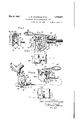
Fig.V 2 is aperspective view, partly in section of one of the remote-control devices showing it disassembled with the operating part removed from the partsecured tothe typewriter.
F ig. 3 is atransverse section ofthe device l shown in-Fig. 2 with the parts connected.
Figi Ais a schematic viewof another re.-l
mote-control. device of the present invention for lperforming another function, showing the operating part removed from the part secured to the typewriter frame, and. showing the connection between the removable part and the phonograph, this device, in the` form shown in the drawings,being adapted to operate the back-space mechanism of th phonograph. i
In these drawings, the typewriting machine is mounted upon a table l1 of a desk l2, which is so constructed, that the table 11 tilts backwardly while the cover 13 swingsv over the lopening through which the typewriter extends when` in use.
The commercial phonograph Mis usually provided with a standV 15 for supporting it on the floor at a height substantially equal to the height of the typewriter desk l2. The stand 15 may be placed .in any-desired position with respect'to the typewriter desk, ac-l cording to the convenience of the operator. But, it usually is arranged as shown in the drawings, so that the-typist mayv easily reach the machine to remove and replace the record 16 or to otherwise :manually control `the mechanism of. the phonograph, such as the stop-and-start mechanism, back-space mechanism, etc.
Now, according tothis invention, in order that the typist may control the stop-andstart mechanism and back-space 'mechanism and other mechanisms if desired, of the and forced through the tube 22.
phonograph, without turning from the typewriter or removing her hand from the keyboard 17 thereof, there is provided manually operable devices adapted to be connected to the typewriter frame and which connect with and operate mechanism of the phonograph 14.
One of these devices is shown in Figs. 2 and It is adapted to operate the clutch mechanism of the phonograph to sto-p-andstart the same while the transcribing is beingA accomplished. This device comprises a plate 18 which has secured thereto a cylinder 19 containing a piston 20 and having an open fi end adapted to receive a nozzle 21 of a flexible hose 22 which reaches to a suitable connection on the phonograph 14. When the piston 2.0 is moved to. the right, as seenV in Fig.v 2, the air in the cylinder 19 is expelled phonograph end of this tube, the air impinges against a piston which operates the clutch mechanism to make it eective. ,hen the clutch mechanism is to be made ineffec- 'f tiveto stop the phonograph, the piston 20 for this purpose. Between the ears 27 thereisloosely mounted upon the bolt for vertical movement, a pawl 29. havin-g a single tooth 30 adapted to engage ratchet teeth 31 on a cam wheel 32 pivotally mounted on a bolt 33 secured in the side plate 24 of' the frame. The pawl 29 is connected to the lever 26' for rotation therewith by means of one of the ears 27 of the operating lever passing into a slot provided in the pawl 29. A spring 36A located between a'bent portion 35 and the lever 26 and guided on a pin 36a in the lever causes the pawl to be normally pressed into Voperative position to engage the teeth 31.
When the key-lever is depressed, the pawl 29) is. rocked with it, and this causes the cam wheel 32` to receive one increment of movement, and when released, the lever 26 returns to normal position under the influence of a spring-37 fastened at one end in one of the ears 27 ofv the lever 26 and having its.
other end fastened in an ear 38 bent inwardly' from` the housing 23. During the rising rIfhe c am wheel 32 is not dragged backward- At .the
ly by this return movement of the pawl 29, because it is frictionally held against movement by the pressure of a spring 39 encircling the rod 33 and located between a washer 40 of the cam wheel and a head 50 on the bolt 33.
The cam wheel 32 is caused to positively operate and control the movement of the piston 20 by means of a follower 51, havinga pai-r of arms 52, one of which is always at'the top portion of one of the cams 53 thereon, while the other arm is always at the bottom portion of opposite cams 5.3. The follower 51 is connected to the piston 2O by a pitman 54, and is Vpivotally mounted on a bolt 55 in the end 24 of the housing 23. Vhen Vthe cam wheel 32 is moved step-by-step by the repeated operations of thev lever 26, its cams 53 i'i'rst move the follower in one direction and then another; one operation moves the follower so as to move the piston 20 to the Yrig-ht as seen in Fig. 2, while the subsequentoperation moves the left, as seen in Fig. 2.
In operation, the typist depresses the lever piston to the .261130. listen to the dictation of .the-phonograph and begins to typewrite. When the dictation isl transmitted to her faster than she can write, she again depresses the lever 26 to stop the phonograph,I while she continues typewri-ting what she has already Y heard.
The housing' 23 which as above stated coinprises a top plate 18 and a side plate 24 also has end plates 24 Within which is embraced the operating mechanism above described.
This housing has a cover-plate-56 secured tor it and having a bracket 57 formed integral therewith adapted to embrace the frame 58 of the typewriter adjacent the key-board 17.
The bracket 5.7, and cover-plate 56 may beV secured to the frame by means of screws 59. which when tightened, impingeA against the inside of the surface of the frame 58 and rmly hold the plate to the frame.
It, is preferable that the cover-plate 5,6 be
detachably connected to the housing 23, so that at the end of the day, or at any time when the operator desires to close her desky by bringing the cover 13 over the opening in which the typewriter is located, the housing 23, with its connected parts and operating lever 26, may be separated from the cover-plate 56 to be placed upon the phonograph. rIjhe tube 22,y thus being out of the way, allows the deskto be closed. Y
To enable this- .to be done` easily and yet to provide a secure connectionbetween the housing 23 and the cover-plate 56, the edges 60 of the ends 24l of the housing 23 are bent outwardly while the cover-plate 56 is provided with inwardly bent edges 61 between which the outwardly bent edges 60 of the housing may slid-e, see Figs. 2 and 3. When the housing` 2.3 is slid onto the cover-plate 56', the top-plate 18 rests npon'the upper surface 62 of the cover-plate.
To operate the back-space mechanism oi separable cover-plate 66 and a bracket 67 with screws 68 by means of which the bracket may be secured to the frame 58 of the typewriter at the side opposite to that at which the lever 26 and housing 28 are mounted.
The lever 63 is provided with depending arms 69 pivotally carrying between them a head 7 0 secured to the internal element 71 of a Bowden-wire 72 whose outer element 7 3 is secured to a sleeve 74- bolted to the end of the housing 65 by a screw 7 5 and a nut 76.
When the lever 63 is depressed, the inner element 71 of the Bowden-wire is moved relatively to the outer element by reason of its connection to the arms 69 of the lever 63 f through the block 70. And, When the lever 63 is released and allowed to rise, the inner element 71 of the Bowden-wire 72 again moves back to its normal position.
At its other end, the Bowden-wire 72 has its outer element 77 secured to a bracket 78,
fixed to the sound-box carriage 79 or" the phonograph, while its inner element is provided with a plunger 80 1n position to engage an arm 81, secured to the back-space key 82 ot the phonograph, which is provided on the -f for a more complete understanding of the same. Sutiice it to say, that the depression of the back-space key-lever 82 moves a pawl 83 into engagement with a stationary rack 84, and through a wedging action, forces the carriage backwardly a predetermined eX- tent, having previously raised the feed-nut 85 from the feed-screw 86 to permit this movement of the carriage.
It will thus be seen that the present ini vention provides simple and convenient means whereby the operator may control the phonograph without removing her hands from the key-board 17 of the typewriter 107 and that such means may be disconnected from the typewriter frame at will Jfor any purpose particularly to allow the typewriter desk to be closed and to allow the phonograph to be moved to another desk it desired. It should also be noted th at the levers 26 and 63 are so shaped and positioned, that the heels of the typists hands may be brought to bear directly upon them when it is desired to operate them.
It will also be noted that spaccfkey-lever82 maybe manually operated by 4direct contact with the typists fingers,`
this mechanism may be controlled selectively directly from the tance therefrom.n i
Having described the invention, what is claimed as new, and for which it is desired to obtain Letters Patent, is:
since the backi phonograph or from a `dis- 1. A remote control device `for phono-n4 y graphs comprising manually-operable means, supporting means therefor adapted to be secured to a typewriter frame, and means for,
separably mounting the manually-operable' means on the said supporting means adapt` ed to permit of the removal thereof without the use of tools. Y
2. A remote control device for phonographs comprising manually-operable means; a-housing for said means; and a clamp separably connected to said housing and adapted to be secured to a typewriter frame, rsaid clamp having a slip joint connection with said housing. i
3. A; remote control device `tor phonographs comprising manually-operable means ;V a support therefor; a bracket removably connected to said support by means oi` a slip joint; and clamping means carried by said bracket for'securing said bracket toa typewriter frame. Y
4. A. remote control device torV phonographs comprising stop-and-start mechanism therefor; a. manually-operable part located at a distance from the phonograph and having a pneumatic piston; means foroperably connecting said pneumatic piston tothe clutch mechanism of the phonograph; and
means operated by the successive manipula-v ion of said manually-operable part for alternately movlng'said pneumatic piston in opposite directionsv to control starting and 3'.'
stopping the phonograph.
A5. A remote control device yfor phonographs comprising manually operable means ist located at a point remote from the phonor graph; power transmitting means connected to said manually operable means and eX- tending to the phonograph; a support adapted to be detachably secured to a type-` writer frame and means for detachably connecting said manually operable means and power transmitting means to said support, said last-named means permitting said manually operable Vmeans to be removed by hand without the use of tools.
6. A remote control device for phono- F graphs comprising in combination, a pneumatic cylinder, a flexible tube connected'V to said cylinder at one` end and at the other end secured to a pneumatic actuating. device on the phonograph; a bracket; means` for securing said bracket to a support remote from thephonograph; and means for detachably mounting said cylinder on said bracket. Y.
7. A remote control device for phonograp-hs comprising; in combination, a cylinder and piston; power transmitting means connected to said cylinder and extending to said phonograph; a linger-piece; and means operated by the `fingerepiece for causing said piston to be moved alternatively inwardly of and outwardly from the cylinder upon each successive manipulation of the linger-piece.
8'. A device of the nature described comprising a cylinder and piston; a Enger-piece; means positively operatedV by the fingen piece for causing the piston to be locked in its innermost position in said cylinder; and
Signed at Bridgeport, in the county of Fairiield and State of Connecticut, this 24th day of February, 1925.
JOSEPH; M. LUGAR-ELLE. JOHN E. RENHOLDT.
means also positively operated by said finger-piece for releasing said lock and moving said piston to its outermost position in said cylinder.
- 9. A device of the. nature described comprising a cylinder and piston; a piston having a stop position and also a start position with respect to said cylinder; a finger-piece; means positively operated by the linger-piece for locking said piston in start position; and meansv also positively operated by said finger-piece for returning said piston to its stop. position.
.10. Al device of the nature described comprising a cylinder and piston; a lever for controlling the movement of the piston; a cam Wheel for operating said lever; and a finger-piece for operating said cam wheel.
1l. A device of the nature described comprising a cylinder and a piston; a lever controlling `the movement of the piston; a cam operating said lever and movable step-bystep to alternately cause the position of the piston to be shifted from one eXtreme to the other in said cylinder; al linger-piece; and means operated by the finger-piece for movin@P said cam step-bystep. .V
12. remote control device for phono,- graphs comprising, in combination, a finger-piece; a device in which the linger-piece is. movably mounted; a bracket adapted to be secured to a supporting means remote from the phonograph; and a sliding connection between said bracket and said device for supporting the finger-piece.
`13. A remote control device for phonographs, comprising a manually operated de'- vice; and supporting means for said device supporting means, and when attached to said supporting means be held in rigid oper'- ati've relation to the keyboard of said typewriting machine.
Priority Applications (1)
| Application Number | Priority Date | Filing Date | Title |
|---|---|---|---|
| US12438A US1908264A (en) | 1925-02-28 | 1925-02-28 | Control device for phonographs, etc. |
Applications Claiming Priority (1)
| Application Number | Priority Date | Filing Date | Title |
|---|---|---|---|
| US12438A US1908264A (en) | 1925-02-28 | 1925-02-28 | Control device for phonographs, etc. |
Publications (1)
| Publication Number | Publication Date |
|---|---|
| US1908264A true US1908264A (en) | 1933-05-09 |
Family
ID=21754971
Family Applications (1)
| Application Number | Title | Priority Date | Filing Date |
|---|---|---|---|
| US12438A Expired - Lifetime US1908264A (en) | 1925-02-28 | 1925-02-28 | Control device for phonographs, etc. |
Country Status (1)
| Country | Link |
|---|---|
| US (1) | US1908264A (en) |
-
1925
- 1925-02-28 US US12438A patent/US1908264A/en not_active Expired - Lifetime
Similar Documents
| Publication | Publication Date | Title |
|---|---|---|
| US993588A (en) | Cabinet for type-writing machines. | |
| US1908264A (en) | Control device for phonographs, etc. | |
| US1983039A (en) | Phonograph | |
| US764070A (en) | Line-lock attachment for type-writing machines. | |
| US690120A (en) | Type-writing machine. | |
| US1955645A (en) | Phonograph | |
| US1823723A (en) | Dictation machine | |
| US369401A (en) | enjalbert | |
| US1469054A (en) | Typewriting machine | |
| US1753450A (en) | Carriage-return mechanism | |
| US1128992A (en) | Tabulating mechanism. | |
| US3394791A (en) | Electric typewriter with separate carrier return and indexing mechanism | |
| US1908737A (en) | Carriage or support for phonographs or similar apparatus | |
| US2010785A (en) | Phonograph | |
| US752868A (en) | A corpora | |
| US2310717A (en) | Typewriting machine | |
| US1469477A (en) | holden | |
| US784494A (en) | Paragraphing-stop for type-writing machines. | |
| US2737281A (en) | Automatic lower case reset attachment for recorder-reproducer | |
| US1649965A (en) | Phonograph | |
| US716720A (en) | Attachment for type-writing machines. | |
| US499263A (en) | Type-writing machine | |
| US1062076A (en) | Type-writing machine. | |
| US944229A (en) | Type-writing machine. | |
| US3521889A (en) | Recording apparatus |