US1908244A - Inner tube for vehicle tires - Google Patents
Inner tube for vehicle tires Download PDFInfo
- Publication number
- US1908244A US1908244A US561409A US56140931A US1908244A US 1908244 A US1908244 A US 1908244A US 561409 A US561409 A US 561409A US 56140931 A US56140931 A US 56140931A US 1908244 A US1908244 A US 1908244A
- Authority
- US
- United States
- Prior art keywords
- tube
- air
- tread
- compartment
- partition
- Prior art date
- Legal status (The legal status is an assumption and is not a legal conclusion. Google has not performed a legal analysis and makes no representation as to the accuracy of the status listed.)
- Expired - Lifetime
Links
- 238000005192 partition Methods 0.000 description 17
- 210000002445 nipple Anatomy 0.000 description 3
- 208000027418 Wounds and injury Diseases 0.000 description 2
- 238000010276 construction Methods 0.000 description 2
- 230000006378 damage Effects 0.000 description 2
- 230000007547 defect Effects 0.000 description 2
- 230000000694 effects Effects 0.000 description 2
- 208000014674 injury Diseases 0.000 description 2
- 101100440699 Drosophila melanogaster corto gene Proteins 0.000 description 1
- 101100161290 Mus musculus Nt5c1b gene Proteins 0.000 description 1
- AWJGUZSYVIVZGP-YUMQZZPRSA-N Pro-Val Chemical compound CC(C)[C@@H](C(O)=O)NC(=O)[C@@H]1CCCN1 AWJGUZSYVIVZGP-YUMQZZPRSA-N 0.000 description 1
- 230000036626 alertness Effects 0.000 description 1
- 230000004048 modification Effects 0.000 description 1
- 238000012986 modification Methods 0.000 description 1
- 108010053725 prolylvaline Proteins 0.000 description 1
- 230000003014 reinforcing effect Effects 0.000 description 1
- 239000002356 single layer Substances 0.000 description 1
Images

Classifications
-
- B—PERFORMING OPERATIONS; TRANSPORTING
- B60—VEHICLES IN GENERAL
- B60C—VEHICLE TYRES; TYRE INFLATION; TYRE CHANGING; CONNECTING VALVES TO INFLATABLE ELASTIC BODIES IN GENERAL; DEVICES OR ARRANGEMENTS RELATED TO TYRES
- B60C5/00—Inflatable pneumatic tyres or inner tubes
- B60C5/20—Inflatable pneumatic tyres or inner tubes having multiple separate inflatable chambers
-
- Y—GENERAL TAGGING OF NEW TECHNOLOGICAL DEVELOPMENTS; GENERAL TAGGING OF CROSS-SECTIONAL TECHNOLOGIES SPANNING OVER SEVERAL SECTIONS OF THE IPC; TECHNICAL SUBJECTS COVERED BY FORMER USPC CROSS-REFERENCE ART COLLECTIONS [XRACs] AND DIGESTS
- Y10—TECHNICAL SUBJECTS COVERED BY FORMER USPC
- Y10T—TECHNICAL SUBJECTS COVERED BY FORMER US CLASSIFICATION
- Y10T152/00—Resilient tires and wheels
- Y10T152/10—Tires, resilient
- Y10T152/10495—Pneumatic tire or inner tube
- Y10T152/10522—Multiple chamber
- Y10T152/10576—Annular chambers
- Y10T152/10612—Annular chambers with simultaneous inflating means
Definitions
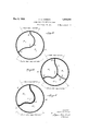
- Fig. 1 is a view in side elevation of a multhe dangers incident to punctures or blowtiple-compartment inner tube constructed in 55 outs. accordance with my invention
- FIG. 2 is a transverse sectional-view therebeen made prior to my invention to provide of taken on the line 2-2 of Fig. 1 but on multiple-compartment tubes for the purpose a larger scale;
- FIG. 3 is a transverse sectional view taken fallen so far short of practicability as to on the line 33 of Fig. 1 but on a larger have failed of both expert and public apscale; proval and hence, so far as I have been able 1
- Fig. 4 is a transverse sectional view corto ascertain, have'failed of commercial sucresponding to Fig. 3 but showing a slight 5 cess. Having made a careful study of prior modification in which a reinforcing web extypes of multiple-compartment tubes and tends between the partition and the tubehaving discovered the fundamental defects wall; and inherent in their design, I have evolved Fig.
- FIG. 5 is a transverse sectional view corthe present multiple-compartment inner tube responding to Fig. 3 but showing the formapresented herein, which has met with ention of the tube by means of two sections asthusiastic approval by tire engineers and Sild together and preferably united by manufacturers as having obviated the inhercementing or vulcanizing. ent defects in previous designs of such tubes.
- the main object of my invention is to in chosen for illustration, I employ an inprovide a multiple compartment inner tube ner tube 10 having the usual ring-like form so constructed that while convenient for use and of substantially circular form in crossand readily inflatable, minimizes to a section.
- a flexible partition 11 having its inneous rupture of more than one compartner edge 12'joining the wall of the tube ment, and insures the stability of a reserveproper at a point substantially in the cencompartment for a length of time at least r l r l plane of the tube and its opposufficient to warn an operator that 3, punc- Slte OI outer edge 13 JOIl'llfig the wall of the ture or other injury has occurred to the tube P0111t to one slde of h h P tire, so that, even under unusual circumof the t so as be substahtlany stances, an automobile or other vehicle need mune to the effects.
- the j o1n1ng of the partitlon, according to my invention thus createsa service air-com- 40 I attain the above and certain other obpartment 14 a a reserve aipcompartment jects which will appear from the following, 15.
- the partition 11 illustrated in Figs. 2, 3 and 4 is of a single layer, as shown, and the tube 10 is of one-piece construction, but if desired and as shown in Fig. 5, the tube proper 10 and the partition 11 may be provided by uniting two initially-independent tube-sections 18 .and 19.
- Air may be supplied to the respective compartments of the tube in any approved man ner, such as by separate and distinct valves, though preferably and as shown in Figs. 1 to 2 I prefer to employ a single double-passage valve having a single inlet-nipple 20 to which a hose may be attached.
- the interior of the nipple 20 connects, as shown, with air-passages 21 and 22 respectively leading into the service air-compartment 14 and the reserve air-compartment 15 and both adapted to be. simultaneously closed to prevent the escape of air by means of a checkvalve 23..
- the body-portion 24 of the said valve is.
- the tube-body 24 thus straddles and embraces the edge of the partiltionand serves to firmly hold the same in p ace.
- An inner tube for vehicle tires having a longitudinal partition dividing the same into separate isolated compartments, one edge of said partition joining the tube wall ad acent to but out of the zone normally comprising the tread portion thereof and its other edge joining the tube wall directly opposite said tread portion, said partition thereby providing a compartment no ortion of the wall of which includes sai portion, and an inflation valve assembled in said tube and having a body provided with means for engagement with said partition and with separate normally-isolated passages leading to the separate compartments and a valve seat at which said passages terminate, a single valve element 00- operating with said seat to open and close said passages simultaneously, and an inlet nipple aflording an entrance opening to said valve, whereby said compartments thou h gornally isolated may be simultaneously mate tread Ill 2.
Landscapes
- Engineering & Computer Science (AREA)
- Mechanical Engineering (AREA)
- Tires In General (AREA)
Description
y 1933- A. 0. HERRON 1,908,244
INNER TUBE FOR VEHICLE TIRES Filed Sept. 5, 1931 2 Sheets-Sheet l 7792340 wear wm POf? r/o/v lzfarnqya May 9, 1933 O fi o 1,908,244
INNER TUBE FOR VEHICLE TIRES Filed Sept. 5, 1931 2 Sheets-Sheet 2 f/wwm mu PORT/OAA I Patented May 9, 1 933 UNITED STATES PATENT OFFICE ALBERT O. EERRON, OF WATERBURYQCONNECTICUT nmnn 'rnnn FOR VEHICLE m Application filed September 5, 1931. Serial No. 581,409.
This invention relates to improvement in juries occurring to the tread-area. of the inner tubes for vehicle tires and particulartube. ly to that class of inner tubes having multi- In the accompanying drawings: ple air-compartments intended to minimize Fig. 1 is a view in side elevation of a multhe dangers incident to punctures or blowtiple-compartment inner tube constructed in 55 outs. accordance with my invention;
I am fully aware that many efforts have Fig. 2 is a transverse sectional-view therebeen made prior to my invention to provide of taken on the line 2-2 of Fig. 1 but on multiple-compartment tubes for the purpose a larger scale;
referred to, but such previous efforts have Fig. 3 is a transverse sectional view taken fallen so far short of practicability as to on the line 33 of Fig. 1 but on a larger have failed of both expert and public apscale; proval and hence, so far as I have been able 1 Fig. 4 is a transverse sectional view corto ascertain, have'failed of commercial sucresponding to Fig. 3 but showing a slight 5 cess. Having made a careful study of prior modification in which a reinforcing web extypes of multiple-compartment tubes and tends between the partition and the tubehaving discovered the fundamental defects wall; and inherent in their design, I have evolved Fig. 5 is a transverse sectional view corthe present multiple-compartment inner tube responding to Fig. 3 but showing the formapresented herein, which has met with ention of the tube by means of two sections asthusiastic approval by tire engineers and sembled together and preferably united by manufacturers as having obviated the inhercementing or vulcanizing. ent defects in previous designs of such tubes. In the embodiment of my invention here- The main object of my invention is to in chosen for illustration, I employ an inprovide a multiple compartment inner tube ner tube 10 having the usual ring-like form so constructed that while convenient for use and of substantially circular form in crossand readily inflatable, minimizes to a section. Extending longitudinally of the marked degree the danger of the simultatube is a flexible partition 11 having its inneous rupture of more than one compartner edge 12'joining the wall of the tube ment, and insures the stability of a reserveproper at a point substantially in the cencompartment for a length of time at least r l r l plane of the tube and its opposufficient to warn an operator that 3, punc- Slte OI outer edge 13 JOIl'llfig the wall of the ture or other injury has occurred to the tube P0111t to one slde of h h P tire, so that, even under unusual circumof the t so as be substahtlany stances, an automobile or other vehicle need mune to the effects. of p other not, with reasonable alertness on the part of Weaknesses developmg m the San]: tread I I area,- u gzfi fg gf g get out control wlth posslble The j o1n1ng of the partitlon, according to my invention thus createsa service air-com- 40 I attain the above and certain other obpartment 14 a a reserve aipcompartment jects which will appear from the following, 15.
by hovel ar rangement of longltudtnal Now it will be noted that the service airp f Wlthln the tube that Provlde, compartment 14 extends over the tread-area 1n addition to what I shall for clarity of def the t b d ill th f b bj 45 scriptioh refer to as a service p to punctures and blow-outs incident to ordi- 95 ment extending over the tread-area of the nary service, and furtherand very importube, a safety or reserve air-compartment tant-that the reserve air-compartment 15 entirely segregated from the tread-area, as is segregated from the tread-area of the distinguished from multiple service-comparttube by the partition 11 owing to the novel ments, all available for rupture from inarrangement of the latter, and is thus not K to the wall of the tube opposite the reservecompartment 15 by a web 16 which is preferably provided with perforations 17 to permit the free flow of air from one side thereof to the other.
The partition 11 illustrated in Figs. 2, 3 and 4 is of a single layer, as shown, and the tube 10 is of one-piece construction, but if desired and as shown in Fig. 5, the tube proper 10 and the partition 11 may be provided by uniting two initially-independent tube-sections 18 .and 19.
Air may be supplied to the respective compartments of the tube in any approved man ner, such as by separate and distinct valves, though preferably and as shown in Figs. 1 to 2 I prefer to employ a single double-passage valve having a single inlet-nipple 20 to which a hose may be attached. The interior of the nipple 20 connects, as shown, with air-passages 21 and 22 respectively leading into the service air-compartment 14 and the reserve air-compartment 15 and both adapted to be. simultaneously closed to prevent the escape of air by means of a checkvalve 23..
The body-portion 24 of the said valve is.
providedat its inner end with a slit or slot '25 into which rejects the localized portion of the inner e ge of the partition 11 adjacent the point of the tube at which the said valve is mounted. The tube-body 24 thus straddles and embraces the edge of the partiltionand serves to firmly hold the same in p ace.
For the purpose of making clear the action of my improved inner tube when in use, let it be supposed that a blow-out has occurred in the tread-area of the shoe in which my improved tube is mounted, which blow-out would affect also the tread-area of the tube. The air from the service-compartment 14 of my improved tube would thus escape and permitthe air in the reservecompartment 15 to expand and cushion the efi'ect of such a blow-out. It is to be borne in' mind, in this connection, that for obvious reasons, such, for instance, as continued wear and incessant contact with the road, the tread-area of a tire is most sub- 'ect to blow-outs and punctures, which rarey occur at places other than the tread-area.
-Now it may be that when a very severe blow-out occurs in the tread-area that such blow-out may cause the partition 11 to ultlmately give way throu h the original blowout hole, but even if suc unlikely occurrence should take place, it will occur only after a delay sufficient to pre-warn the driver and.
thus put him on the alert and insure proper control of the automobile, or other vehicle, before disastrous results can occur.
lVha-t I wish, therefore, to point out with emphasis is that by the novel arrangement of the serviceand reverse-compartments 14 and 15, I minimize, if not preclude, the dangerous effects of a blow-out in such manner that the reserve-compartment will not be simultaneously affected with the service-compartment by a blow-out opening up the latter, as it will be noted, and as before pointed out, that the reserve-compartment is segregated from the tread-area of the tube by the novel construction and arrangement of parts above described, in dis tinction to multiple-compartment tubes heretofore proposed, which have had all of the said compartments available for rupture from injuries occurring to the tread area.
It will be understood by those skilled in the art that my invention may assume varied physical forms without departing from my inventive concept, and I, therefore, do not limit myself to the specific embodiments herein. chosen for illustration, but only as indicated in the appended claims.
I claim:
1. An inner tube for vehicle tires, having a longitudinal partition dividing the same into separate isolated compartments, one edge of said partition joining the tube wall ad acent to but out of the zone normally comprising the tread portion thereof and its other edge joining the tube wall directly opposite said tread portion, said partition thereby providing a compartment no ortion of the wall of which includes sai portion, and an inflation valve assembled in said tube and having a body provided with means for engagement with said partition and with separate normally-isolated passages leading to the separate compartments and a valve seat at which said passages terminate, a single valve element 00- operating with said seat to open and close said passages simultaneously, and an inlet nipple aflording an entrance opening to said valve, whereby said compartments thou h gornally isolated may be simultaneously mate tread Ill 2. The combination with an inner tube I for vehicle tires having a longitudinal partition dividing the same into two air-comvided with a slit straddling and embracing said partition, and said air-valve formed with two air-passages located respectively on opposite sides of the said slit and extending into the said air-compartments respectively.
3; The combination with an inner tube for vehicle tires having a longitudinal partition dividing the same into two air-compartments, of an air-valve having a body provided with a flange-like head extending laterally therefrom and arranged within the said tube in position to engage said partition,"said partition separated from said tube at that portion adjacent to the flangelike head and said head rovided with a slit straddling and embracing the separated portion of said partition, said body having two air passages communicating respectively with the said two air-compartments but normally isolated from each other, a valve seat at which said passages terminate, a single valve element cooperating with said seat to open and close both of said air passzkges simultaneously, and an inlet nipple a ording an entrance opening to said valve, whereby said compartments though normal- 1y separate may be simultaneously inflated.
In testimony whereof, I have signed this specification.
ALBERT O. HERRON.
Priority Applications (1)
| Application Number | Priority Date | Filing Date | Title |
|---|---|---|---|
| US561409A US1908244A (en) | 1931-09-05 | 1931-09-05 | Inner tube for vehicle tires |
Applications Claiming Priority (1)
| Application Number | Priority Date | Filing Date | Title |
|---|---|---|---|
| US561409A US1908244A (en) | 1931-09-05 | 1931-09-05 | Inner tube for vehicle tires |
Publications (1)
| Publication Number | Publication Date |
|---|---|
| US1908244A true US1908244A (en) | 1933-05-09 |
Family
ID=24241849
Family Applications (1)
| Application Number | Title | Priority Date | Filing Date |
|---|---|---|---|
| US561409A Expired - Lifetime US1908244A (en) | 1931-09-05 | 1931-09-05 | Inner tube for vehicle tires |
Country Status (1)
| Country | Link |
|---|---|
| US (1) | US1908244A (en) |
Cited By (2)
| Publication number | Priority date | Publication date | Assignee | Title |
|---|---|---|---|---|
| US4884609A (en) * | 1987-10-02 | 1989-12-05 | Ho I Chung | No-flat tire insert |
| US5693161A (en) * | 1995-05-18 | 1997-12-02 | Ho; I-Chung | No-flat tire and no flat tire insert |
-
1931
- 1931-09-05 US US561409A patent/US1908244A/en not_active Expired - Lifetime
Cited By (2)
| Publication number | Priority date | Publication date | Assignee | Title |
|---|---|---|---|---|
| US4884609A (en) * | 1987-10-02 | 1989-12-05 | Ho I Chung | No-flat tire insert |
| US5693161A (en) * | 1995-05-18 | 1997-12-02 | Ho; I-Chung | No-flat tire and no flat tire insert |
Similar Documents
| Publication | Publication Date | Title |
|---|---|---|
| US1908244A (en) | Inner tube for vehicle tires | |
| US2354912A (en) | Safety inner tube | |
| US2560609A (en) | Tire tube | |
| US2047859A (en) | Vented rubber article | |
| US2064694A (en) | Pneumatic tire | |
| US2173065A (en) | Safety inner tube for pneumatic tires | |
| US1395770A (en) | Pneumatic tire | |
| US1774892A (en) | Inner tube for pneumatic tires | |
| US2665731A (en) | Tubeless tire | |
| US1202695A (en) | Inner tube for pneumatic tires. | |
| US2033882A (en) | Rim for venting tires | |
| US1640844A (en) | Pneumatic tire | |
| US1303998A (en) | Harry l | |
| US2295457A (en) | Valve | |
| US1460775A (en) | Tire structure | |
| US1215717A (en) | Pneumatic tire. | |
| US1952221A (en) | Inner tube for automobile tires | |
| US2152131A (en) | Pneumatic tire | |
| US1223827A (en) | Inner tube to be used on automobiles and other conveyances. | |
| US2469300A (en) | Tire | |
| US985397A (en) | Tire for vehicle-wheels. | |
| US1465867A (en) | Inner tube | |
| US2040759A (en) | Safety tire | |
| US2307002A (en) | Safety tubes or the like | |
| US2290687A (en) | Inner tube |