US1908234A - Opposed door jail construction - Google Patents
Opposed door jail construction Download PDFInfo
- Publication number
- US1908234A US1908234A US606819A US60681932A US1908234A US 1908234 A US1908234 A US 1908234A US 606819 A US606819 A US 606819A US 60681932 A US60681932 A US 60681932A US 1908234 A US1908234 A US 1908234A
- Authority
- US
- United States
- Prior art keywords
- door
- pull bar
- doors
- latch bolt
- gap
- Prior art date
- Legal status (The legal status is an assumption and is not a legal conclusion. Google has not performed a legal analysis and makes no representation as to the accuracy of the status listed.)
- Expired - Lifetime
Links
- 238000010276 construction Methods 0.000 title description 13
- 230000000694 effects Effects 0.000 description 3
- XEEYBQQBJWHFJM-UHFFFAOYSA-N Iron Chemical compound [Fe] XEEYBQQBJWHFJM-UHFFFAOYSA-N 0.000 description 2
- 238000009428 plumbing Methods 0.000 description 2
- FGRBYDKOBBBPOI-UHFFFAOYSA-N 10,10-dioxo-2-[4-(N-phenylanilino)phenyl]thioxanthen-9-one Chemical compound O=C1c2ccccc2S(=O)(=O)c2ccc(cc12)-c1ccc(cc1)N(c1ccccc1)c1ccccc1 FGRBYDKOBBBPOI-UHFFFAOYSA-N 0.000 description 1
- 241001155433 Centrarchus macropterus Species 0.000 description 1
- 241000490229 Eucephalus Species 0.000 description 1
- 230000008878 coupling Effects 0.000 description 1
- 238000010168 coupling process Methods 0.000 description 1
- 238000005859 coupling reaction Methods 0.000 description 1
- 230000001419 dependent effect Effects 0.000 description 1
- 238000009434 installation Methods 0.000 description 1
- 229910052742 iron Inorganic materials 0.000 description 1
Images

Classifications
-
- E—FIXED CONSTRUCTIONS
- E04—BUILDING
- E04H—BUILDINGS OR LIKE STRUCTURES FOR PARTICULAR PURPOSES; SWIMMING OR SPLASH BATHS OR POOLS; MASTS; FENCING; TENTS OR CANOPIES, IN GENERAL
- E04H3/00—Buildings or groups of buildings for public or similar purposes; Institutions, e.g. infirmaries or prisons
- E04H3/08—Hospitals, infirmaries, or the like; Schools; Prisons
Definitions
- This invention relates to jail construction of the type characterized bya row of cells having sliding doors.
- the cells have left and right relation as to their doors, so that only alternate pilasters need be enlarged to accommodate plumbing connections.
- a contemporary requirement in the art is provision for controlling all ofthe doors of the row from a removed location as at the end. of the row, whereby an operator at such location may at his will open, close, and lock in open and closed position, any or all of the doors, and at such location'may at all times be informed of the position and condition of each door.
- the principal object of this invention is to provide such control of doors having the described left and right relation in a row of cells.
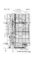
- Fig. 1 is a view generally in front elevation of an adjacent pair of cells in a row, parts being removed and others broken away to show de- 35 tails of construction, thedoors being shown in closed position, that of the first cell being unlocked and that of the second cell locked;
- Fig. 2 is a detail showing in plan view certain of the door-actuating parts appearing in F ig. 1;
- F ig. 3 is a view following that of Fig.2 but illustrating the relation of the parts shown in a three cell row, F ig. being a continuationof Fig. 3;
- Fig. 4 is an enlarged detail in elevation of lock-controlling parts of the doors of the three cells, the positions of the parts being those-wherein the first door is unlocked, the second door locked closed and the third door locked open.
- cells Nos. 1, 2 and 3 are the first three cells of a 1932. Serial No. 606,819.
- each door 3 is carried upon a hanger 6 having rollers 7 movable upon a way to open from and, close against the smaller pilaster 4. of its cell.
- the doors are of the sliding type, mounted for movement in a common plane, generally that of the common front'wall of the row of cells.
- the opening of each cell to be controlled by itsdoor is located adjacent the near small pil'aster 4. Consequently each pilaster 4' constitutes the abutment against which a pair of doors close, and the'd'o'ors of an adjacent pair of cells have opposite opening and closing directions.
- a gap nut 8 is provided for its actuation.
- This gap nut is arranged for operator-controlled movement along a way corresponding to. that of the door. Connection of the door with the gap nut, that the former may be caused to follow the latter, is had by a latch bolt 9 carried by the hanger 6 and vertically movable thereupon, and engageable, dependent upon its vertical adjustment, in a notch 10 in the gap nut.
- Such adjustment of the latch bolt 9 is had by its support upon a latch bolt bar 11 along which the latch bolt moves with the door.
- the latch bolt bar is under. the control of an operator at a removed location by manipulation of a lever 12 preferably located: at the end of the cell'row as is usual in the art and as shown Figs. 1 and 2.
- the connection between the lever 12 and its latch bolt bar 11 includes a cable means 13 leading, with a reversing effect provided by the roller 14 of fixed pivot, to an arm of the bell crank 15.
- This bell crank 15 has connection by a link 16 -with a second bell crank 17 which in turn has connection by a link 18 with the latch bolt bar 11.
- the latch bolt bar is carried at one end upon a roller 19 and has a cam surface 20 cooperable therewith. At its opposite end the latch bolt bar has connection by a link 21 with a bracket 22.
- the lever 12 has three positions as indicated, as consequently does the latch bolt 9. In its lowermost position the latch bolt is fully engaged in the notch 10 of its gap nut 8 so that the door is positively connected with the latter for movement in either openingor closing direction. Also, in this position of the latch bolt, if the gap nut has be'enremoved to the left, Fig. 1, before lowering of the latch bolt, subsequent motion of the gap nut to the right will cause latching of the latch bolt in the notch 10 because of the cam surface illustrated at the righthand end of the gap nut.v It will be apparent that when the door is closed and the gap nut is in its extreme right-hand position, the door will be locked thereby against opening. Thus, uppermost position of the lever 12 corresponds with locked closed position of the door, if the gap nut be at the closed end of its stroke.
- the latch bolt is raised sufliciently to clear the gap nut on one side of its notch 10 but not to clear in the other direction, the latch bolt having uneven projections on the opposite sides of its notch, as illustrated Fig. 1.
- the latch bolt bar ll is provided with a cam riser at 23 whose function it is to raise the latch bolt 9 one step above that corresponding to the setting of the lever 12, as the door closes.
- the latch bolt will be automatically raised to allow return or opening motion of tlhe gap nut without, however, affecting the c oor.
- the door-controlling mechanism may preferably include the structure illustrated at 24 and at 24a, forming no part of this invention, but fully illustrated and described in Patent No. 1,811,246, issued June 23, 1931, to Shank et al., and in Patent No. 1,665,243, issued April 10, 1928, to VVhitehouse, respectively.
- the door may be locked in closed position it is provided with a tongue 25, the pilaster 4 is provided with an opening to receive this tongue, and a lock bolt 26 is mounted in the pilaster for vertical motion to engage the tongue 25 by a notch provided in the latter.
- the bolt 26 has an associated spring 27 yieldably urging the bolt to locking position, and the bolt and tongue are chamfered as indicated Fig. 1, to have latching engagement.
- the bolt 26 is associated with the mechanism which controls the latch bolt barv 11, so
- Such mechanism comprises a pull rod 28 and lever 29 arranged to receive motion from the bell crank 15 such that as the'latch bolt bar 11 is raised the lock bolt 26 is lowered.
- the proportion and arrangement of the parts is such that only when the lever 12 is in uppermost-position will the lock bolt 26 be in position to engage the tongue 25 ofthe door. That the lever may not be raised to this position to indicate the locking of its door, unless and until the door be entirely closed and thus actually locked, mechanism generally indicated at 30 and completely disclosed (Fig. 7) in the said copending joint application, is preferably provided.
- the door 3a of cell No. 2 is provided with control mechanism to be actuated by the lever 12a adjacent the lever 12, and similar in every respect to the mechanism for the door 3 with two exceptions: First, the parts for the door 3aare in right-hand relation to the left-hand relation of the partsfor the door 3. Second'fthe cable connection 13a goes directly to the bell crank lever 15 instead of by way' of a roller such as at 14.
- the door 3?; of the third cell has control mechanism exactly similar to that of the door 3 of the first cell, the cable 135 controlled by a thirdlever 12b passing overthe roller lab-before attachment to the corresponding bell crank 15b.
- the gap nut 8 of the door 3 of the first cell has a rigidly associated pull bar 31 as is usual in the art. But this pull bar does not. extend to the operators station as heretofore. Instead, it extends in the opposite direction and is provided with a rack 32 meshing with an idler pinion 33. The pinion 33 in turn meshes with a rack part 34: on a pull bar 35.
- This pull bar35 is a master pull bar and extends along the cell front wall of the row of cells, and to the operators station where it has an actuating rack part 36 engaged by an actuating worm 37. The worm in turn is controlled by a shaft 38, through gearing indicated at 39, chain 40 and shaft 41.
- the gap nut 8a of the door 3a of the second cell is to have motion opposite to that of the gap nut 8 of the first door. Since the doors are to be arranged in a common plane, the gap nuts should be arranged in a line to have movement therealong. Consequently the gap nut 8a of the second door 30, is secured with the master pull bar 35 to move therewith, but is offset therefrom as by a bracket 42 into alignment with the gap nut 8.
- the gap nut 86 of the door 3?) of the third cell of the row has actuation through a reverse pull bar 317) actuated from the master pull bar by an idler pinion 33b in a manner similar to that by which the gap nut 8 of the first door has actuation, the gap nut 87) of the third door being aligned with the gap nuts of theother doors. From what has been described it willbe apparent that the gap nuts of the left-hand doors have simultaneous motion with those of the right hand doors but in the opposite direction. Thus those of the doors which have" engagement with their gap nuts may be together either opened or closed, although theyactually move in opposite absolute directions, by motion of the master pull bar'which is under the control of-the operator.
- a jail construction including a pair of cells having sliding doors arranged to close in opposite directions, a master pull bar arranged for movement along said cells, said pull bar and one of said doors having cooperative means adapted to impart the pull bar motion to the door, a pull bar for the other door arranged for movement in the directions of that of said master pull bar, said second door and its pull bar having cooperative means adapted to impart the motion of said second pull bar to said second door, and means associating said second pull bar with said master pull bar for actuation of the'former by the latter in the reverse direction.
- a jail construction including a pair of cells having sliding doors arranged to close in opposite directions, amaster pullv bar arranged for movement along said cells, said pull bar and one of said doors having cooperative means adapted to impart the pull bar motion to the door, a pull bar for the other door arranged for movement in the directions of that of said master pull bar, said second door and its pull bar having cooperative means adapted to impart the motion of said second pull bar to said second door, and means associating said second pull ICS bar with said master pull bar for actuation of the former by the latter in the reverse direction, said means comprising rack parts on said pull bars and gear means there between.
- a jail construction including a row of cells each having a sliding door, a master pull bar arranged for movement along said row, said pull bar and some of said doors having cooperative means adapted to impart the pull bar motion to the latter, another door having a reverse pull bar arranged for movement in the directions of that of said master pull bar, said other door and its pull bar having cooperative means adapted to impart the reverse pull bar motion to said other door, said reverse pull bar having means associating it with said master pull bar for actuation thereby but in the reverse direction.
- a jail construction including a row 7 of cells each having a sliding door, a master pull bar arranged for movement along said row, said pull bar and alternate of said doors having cooperative means adapted to impart the pull bar motion to said alternate doors, intermediate doors having reverse pull bars arranged for movement in the directions of that of said master pull bar, said intermediate doors and their pull bars having cooperative means adapted to impart the reverse pull bar motion to said intermediate doors, each reverse pull bar having means associating it with said master pull bar for actuation thereby but in the reverse direction.
- a master pull bar arranged for movement along said cells, said pull bar having an ofl:'set gap nut part for actuation of one of said doors, a pull bar for another door arranged for movement in the directions of that of said master pullbar, and having a gap nut part for actuation of said other door, said pull bars having their gap nutparts arranged to move along a common plane, and means associating said second pull bar with said master pull bar for actuation of the former by the latter in thereverse direction.
- a jail construction including cells having sliding doors arranged in a common planeto close in opposite directions, a master pull bar arranged for movement along said cells, said pull bar having a horizontally offset gap nut'part for actuation of one of said doors, a pull bar for another door arranged for movement in the directions of that of said master pull bar, and having a gap nut part for actuation of said other door arranged to move in the plane of movement of the gap nut of said master pull bar, and means associating said-second pull bar with said master pull bar for actuation of the former by the-latter in the reverse direction.
- a jail construction including a row of cells each having a sliding door, a master pull bar arranged for movement along said row, said pull bar having an offset gap nut part for actuationof one of said doors, an-
Landscapes
- Engineering & Computer Science (AREA)
- Architecture (AREA)
- Health & Medical Sciences (AREA)
- Public Health (AREA)
- Civil Engineering (AREA)
- Structural Engineering (AREA)
- Power-Operated Mechanisms For Wings (AREA)
Description
M y 1933. H. D. GARBER OPPOSED DOOR JAIL CONSTRUCTION Flled Ap11l22, 1932 2 Sheets-Sheet 1 w Am 4: w a. 4 I M wx May 9, 1933. H. D. GARBER OPPOSED DOOR JAIL CONSTRUCTION Filed April22, 1952 2 Sheets-Sheet 2 flier/y J. krber Patented May 9, 1933 UNITED STATES PATENT:
OFFICE HARRY I). GARIBER, OF CUYAHOGA FALLS, OHIO, ASSIGNOR TO THE VAN DORN, IRON WORKS COMPANY, OF CLEVELAND, OHIO, A CORPORATION OF OHIO OPPOSED DOOR TAIL CONSTRUCTION Application filed April 22,
This invention relates to jail construction of the type characterized bya row of cells having sliding doors. In some such installations it is desirable that the cells have left and right relation as to their doors, so that only alternate pilasters need be enlarged to accommodate plumbing connections. This makes it preferable that the doors of adja cent cells open and close in reverse directions. V y
A contemporary requirement in the art is provision for controlling all ofthe doors of the row from a removed location as at the end. of the row, whereby an operator at such location may at his will open, close, and lock in open and closed position, any or all of the doors, and at such location'may at all times be informed of the position and condition of each door.
The principal object of this invention is to provide such control of doors having the described left and right relation in a row of cells.
Other objects are to accomplish this purpose by novel and improved means as will appear.
The exact nature of this invention together with further objects and advantages thereof will be apparent from the following description taken in connection with the accompanying drawings in which Fig. 1 is a view generally in front elevation of an adjacent pair of cells in a row, parts being removed and others broken away to show de- 35 tails of construction, thedoors being shown in closed position, that of the first cell being unlocked and that of the second cell locked; Fig. 2 is a detail showing in plan view certain of the door-actuating parts appearing in F ig. 1; F ig. 3 is a view following that of Fig.2 but illustrating the relation of the parts shown in a three cell row, F ig. being a continuationof Fig. 3; Fig. 4 is an enlarged detail in elevation of lock-controlling parts of the doors of the three cells, the positions of the parts being those-wherein the first door is unlocked, the second door locked closed and the third door locked open.
\Vith reference now to the drawings, cells Nos. 1, 2 and 3 are the first three cells of a 1932. Serial No. 606,819.
walls and the cell front wall, and pipe shafts 5 may be provided at alternate of these intersections asindicated Fig. 3a, to enclose plumbing, etc. Each door 3 is carried upon a hanger 6 having rollers 7 movable upon a way to open from and, close against the smaller pilaster 4. of its cell. In other, words the doors are of the sliding type, mounted for movement in a common plane, generally that of the common front'wall of the row of cells. v The opening of each cell to be controlled by itsdoor is located adjacent the near small pil'aster 4. Consequently each pilaster 4' constitutes the abutment against which a pair of doors close, and the'd'o'ors of an adjacent pair of cells have opposite opening and closing directions. Thus in Fig. 1 the door 3 of cell No. 1 doses to the right simjfd the door 3a of cell No. 2 closes to the 1 Considering now only the first door 3 of cell No. 1, a gap nut 8 is provided for its actuation. This gap nut is arranged for operator-controlled movement along a way corresponding to. that of the door. Connection of the door with the gap nut, that the former may be caused to follow the latter, is had by a latch bolt 9 carried by the hanger 6 and vertically movable thereupon, and engageable, dependent upon its vertical adjustment, in a notch 10 in the gap nut.
Such adjustment of the latch bolt 9 is had by its support upon a latch bolt bar 11 along which the latch bolt moves with the door.
The latch bolt bar is under. the control of an operator at a removed location by manipulation of a lever 12 preferably located: at the end of the cell'row as is usual in the art and as shown Figs. 1 and 2. The connection between the lever 12 and its latch bolt bar 11 includes a cable means 13 leading, with a reversing effect provided by the roller 14 of fixed pivot, to an arm of the bell crank 15. This bell crank 15 has connection by a link 16 -with a second bell crank 17 which in turn has connection by a link 18 with the latch bolt bar 11. The latch bolt bar is carried at one end upon a roller 19 and has a cam surface 20 cooperable therewith. At its opposite end the latch bolt bar has connection by a link 21 with a bracket 22. It will be evident that the arrangement is such that as the lever 12 is moved downwardly the latch bolt bar 11 will be moved to the right Fig. 1, and as the latch bolt bar is thus moved it will be caused to rise and thus raise the latch bolt 9 regardless of the position of the door 3 along its way. In fact the general arrangement and operation of the parts just described, by which the latch bolt bar is controlled, is identical with that disclosed morein detail in my joint application with lValter Wm. Meier, Serial No. 592,504, filed February 12, 1932, with the exception that for this door 3 of the No. 1 cell, in this application parts are reversed left and right and the motion of the line 13 is reversed by its bend about the roller 14.
j The lever 12 has three positions as indicated, as consequently does the latch bolt 9. In its lowermost position the latch bolt is fully engaged in the notch 10 of its gap nut 8 so that the door is positively connected with the latter for movement in either openingor closing direction. Also, in this position of the latch bolt, if the gap nut has be'enremoved to the left, Fig. 1, before lowering of the latch bolt, subsequent motion of the gap nut to the right will cause latching of the latch bolt in the notch 10 because of the cam surface illustrated at the righthand end of the gap nut.v It will be apparent that when the door is closed and the gap nut is in its extreme right-hand position, the door will be locked thereby against opening. Thus, uppermost position of the lever 12 corresponds with locked closed position of the door, if the gap nut be at the closed end of its stroke.
i In the intermediate position of the handle 12 and latch bolt 9, which is that illustrated for door 3 of cell No. 1 in Figs. 1 and 4, the latch bolt is raised sufliciently to clear the gap nut on one side of its notch 10 but not to clear in the other direction, the latch bolt having uneven projections on the opposite sides of its notch, as illustrated Fig. 1. In
this position-of the latch bolt, therefore, mo
tion of the gap nut 8 in closing direction will close the door but motion in the oppo-' site direction will not cause the door to open. Also, if the'door be open and the gap nut to the right thereof, gap nut motion to the left sufliclent' to pass the latch bolt, followed by door closing motion will close the door owing to the latching effect provided by the cam surface shown at the left end of the gap nut.
Vhen the lever 12 is moved to lowermost position the latch bolt 9 is in uppermost position, one wherein it entirely clears the gap nut 8 regardless of the position of the latter, so that so far as the gap nut is concerned the door is free to be opened or closed by hand.
The latch bolt bar llis provided with a cam riser at 23 whose function it is to raise the latch bolt 9 one step above that corresponding to the setting of the lever 12, as the door closes. Thus if the lever 12 is in intermediate position and the door be closed, the latch bolt will be automatically raised to allow return or opening motion of tlhe gap nut without, however, affecting the c oor.
The door-controlling mechanism may preferably include the structure illustrated at 24 and at 24a, forming no part of this invention, but fully illustrated and described in Patent No. 1,811,246, issued June 23, 1931, to Shank et al., and in Patent No. 1,665,243, issued April 10, 1928, to VVhitehouse, respectively.
That the door may be locked in closed position it is provided with a tongue 25, the pilaster 4 is provided with an opening to receive this tongue, and a lock bolt 26 is mounted in the pilaster for vertical motion to engage the tongue 25 by a notch provided in the latter. The bolt 26 has an associated spring 27 yieldably urging the bolt to locking position, and the bolt and tongue are chamfered as indicated Fig. 1, to have latching engagement.
The bolt 26 is associated with the mechanism which controls the latch bolt barv 11, so
that manipulation of the lever 12 controls the lock bolt 26 as well as the latch bolt 9. As here shown such mechanism comprises a pull rod 28 and lever 29 arranged to receive motion from the bell crank 15 such that as the'latch bolt bar 11 is raised the lock bolt 26 is lowered. The proportion and arrangement of the parts is such that only when the lever 12 is in uppermost-position will the lock bolt 26 be in position to engage the tongue 25 ofthe door. That the lever may not be raised to this position to indicate the locking of its door, unless and until the door be entirely closed and thus actually locked, mechanism generally indicated at 30 and completely disclosed (Fig. 7) in the said copending joint application, is preferably provided.
The door 3a of cell No. 2 is provided with control mechanism to be actuated by the lever 12a adjacent the lever 12, and similar in every respect to the mechanism for the door 3 with two exceptions: First, the parts for the door 3aare in right-hand relation to the left-hand relation of the partsfor the door 3. Second'fthe cable connection 13a goes directly to the bell crank lever 15 instead of by way' of a roller such as at 14.
' The door 3?; of the third cell has control mechanism exactly similar to that of the door 3 of the first cell, the cable 135 controlled by a thirdlever 12b passing overthe roller lab-before attachment to the corresponding bell crank 15b.
Thus it will be apparent that similar manipulation of the levers 12 will efiect similar results as to the doors controlled by the levers.
"What remains to be described is the arrangement and manner of actuation of" the gap nuts 8 of the several doors. Obviously the gap nuts of the left-hand doors must move in opposite directions to those of the rightehand doors if the doors are to be simultaneously moved with similar effect.
The gap nut 8 of the door 3 of the first cell has a rigidly associated pull bar 31 as is usual in the art. But this pull bar does not. extend to the operators station as heretofore. Instead, it extends in the opposite direction and is provided with a rack 32 meshing with an idler pinion 33. The pinion 33 in turn meshes with a rack part 34: on a pull bar 35. This pull bar35 is a master pull bar and extends along the cell front wall of the row of cells, and to the operators station where it has an actuating rack part 36 engaged by an actuating worm 37. The worm in turn is controlled by a shaft 38, through gearing indicated at 39, chain 40 and shaft 41. The arrangement of these last described parts, whereby the master pull bar 35 may be moved endwise along the cell fronts, is more fully described and illustrated in the copending application to which reference has been made. t will be apparent from Figs. 2 and 3 that when the master pull bar is moved in one direction the pull bar 31 of the gap nut 8 will be moved in the opposite direction. The pull bar 31 may thus be considered a reverse pull bar, individual to its door 3.
The gap nut 8a of the door 3a of the second cell is to have motion opposite to that of the gap nut 8 of the first door. Since the doors are to be arranged in a common plane, the gap nuts should be arranged in a line to have movement therealong. Consequently the gap nut 8a of the second door 30, is secured with the master pull bar 35 to move therewith, but is offset therefrom as by a bracket 42 into alignment with the gap nut 8.
The gap nut 86 of the door 3?) of the third cell of the row, has actuation through a reverse pull bar 317) actuated from the master pull bar by an idler pinion 33b in a manner similar to that by which the gap nut 8 of the first door has actuation, the gap nut 87) of the third door being aligned with the gap nuts of theother doors. From what has been described it willbe apparent that the gap nuts of the left-hand doors have simultaneous motion with those of the right hand doors but in the opposite direction. Thus those of the doors which have" engagement with their gap nuts may be together either opened or closed, although theyactually move in opposite absolute directions, by motion of the master pull bar'which is under the control of-the operator.
The result of the entire arrangement described will be that although the cell row includes left and right handdoor arrangements, nevertheless, so far as the operator is concerned his control of the doors is each door,'meansinter-associating said gap nuts for simultaneous motion in opposite oirections by a common actuator, and means for selectively coupling each door with its gap. nut, from saidlocation.
2. In a jail construction including a pair of cells having sliding doors arranged to close in opposite directions, a master pull bar arranged for movement along said cells, said pull bar and one of said doors having cooperative means adapted to impart the pull bar motion to the door, a pull bar for the other door arranged for movement in the directions of that of said master pull bar, said second door and its pull bar having cooperative means adapted to impart the motion of said second pull bar to said second door, and means associating said second pull bar with said master pull bar for actuation of the'former by the latter in the reverse direction. Y
3. In a jail construction including a pair of cells having sliding doors arranged to close in opposite directions, amaster pullv bar arranged for movement along said cells, said pull bar and one of said doors having cooperative means adapted to impart the pull bar motion to the door, a pull bar for the other door arranged for movement in the directions of that of said master pull bar, said second door and its pull bar having cooperative means adapted to impart the motion of said second pull bar to said second door, and means associating said second pull ICS bar with said master pull bar for actuation of the former by the latter in the reverse direction, said means comprising rack parts on said pull bars and gear means there between.
4:. In a jail construction including a row of cells each having a sliding door, a master pull bar arranged for movement along said row, said pull bar and some of said doors having cooperative means adapted to impart the pull bar motion to the latter, another door having a reverse pull bar arranged for movement in the directions of that of said master pull bar, said other door and its pull bar having cooperative means adapted to impart the reverse pull bar motion to said other door, said reverse pull bar having means associating it with said master pull bar for actuation thereby but in the reverse direction.
5. In a jail construction including a row 7 of cells each having a sliding door, a master pull bar arranged for movement along said row, said pull bar and alternate of said doors having cooperative means adapted to impart the pull bar motion to said alternate doors, intermediate doors having reverse pull bars arranged for movement in the directions of that of said master pull bar, said intermediate doors and their pull bars having cooperative means adapted to impart the reverse pull bar motion to said intermediate doors, each reverse pull bar having means associating it with said master pull bar for actuation thereby but in the reverse direction.
6. In a jail construction including cells having sliding doors arranged in a common plane to close in opposite directions, a master pull bar arranged for movement along said cells, said pull bar having an ofl:'set gap nut part for actuation of one of said doors, a pull bar for another door arranged for movement in the directions of that of said master pullbar, and having a gap nut part for actuation of said other door, said pull bars having their gap nutparts arranged to move along a common plane, and means associating said second pull bar with said master pull bar for actuation of the former by the latter in thereverse direction.
7. In a jail construction including cells having sliding doors arranged in a common planeto close in opposite directions, a master pull bar arranged for movement along said cells, said pull bar having a horizontally offset gap nut'part for actuation of one of said doors, a pull bar for another door arranged for movement in the directions of that of said master pull bar, and having a gap nut part for actuation of said other door arranged to move in the plane of movement of the gap nut of said master pull bar, and means associating said-second pull bar with said master pull bar for actuation of the former by the-latter in the reverse direction. a 5
8. In a jail construction including a row of cells each having a sliding door, a master pull bar arranged for movement along said row, said pull bar having an offset gap nut part for actuationof one of said doors, an-
other door having a reverse pull bar ar-V signature.
HARRY D. GARBER.
Priority Applications (1)
| Application Number | Priority Date | Filing Date | Title |
|---|---|---|---|
| US606819A US1908234A (en) | 1932-04-22 | 1932-04-22 | Opposed door jail construction |
Applications Claiming Priority (1)
| Application Number | Priority Date | Filing Date | Title |
|---|---|---|---|
| US606819A US1908234A (en) | 1932-04-22 | 1932-04-22 | Opposed door jail construction |
Publications (1)
| Publication Number | Publication Date |
|---|---|
| US1908234A true US1908234A (en) | 1933-05-09 |
Family
ID=24429596
Family Applications (1)
| Application Number | Title | Priority Date | Filing Date |
|---|---|---|---|
| US606819A Expired - Lifetime US1908234A (en) | 1932-04-22 | 1932-04-22 | Opposed door jail construction |
Country Status (1)
| Country | Link |
|---|---|
| US (1) | US1908234A (en) |
-
1932
- 1932-04-22 US US606819A patent/US1908234A/en not_active Expired - Lifetime
Similar Documents
| Publication | Publication Date | Title |
|---|---|---|
| US2124970A (en) | Closing and locking device for overhead garage doors | |
| US2094990A (en) | Casement window | |
| US1908234A (en) | Opposed door jail construction | |
| US1891485A (en) | Window | |
| US2442363A (en) | Window structures | |
| US1594513A (en) | Apparatus for operating sliding doors and the like | |
| US1014960A (en) | Locking mechanism for doors. | |
| US2152055A (en) | Window regulator | |
| US2837182A (en) | Keyless locking and operating systems for cell doors | |
| US3269059A (en) | Vertically adjustable supporting means for laterally movable doors | |
| US3009545A (en) | Jail locking devices | |
| US2262674A (en) | Locking and operating mechanism for cell doors | |
| US2146552A (en) | Jail door operating and locking system | |
| US3606424A (en) | Door locking device | |
| US2077957A (en) | Gate operating means | |
| US2104661A (en) | Safety locking and operating system for cell doors | |
| US2421900A (en) | Emergency door apparatus | |
| US1811230A (en) | Jail door mechanism | |
| US1122443A (en) | Cell-door-operating mechanism. | |
| US2089011A (en) | Locking and operating mechanism for doors | |
| US1515376A (en) | Control system for ventilating sash units | |
| US1836697A (en) | Lock and door operating mechanism | |
| US1658148A (en) | Jail-door-locking mechanism | |
| US3028639A (en) | Aircraft hanger doors | |
| US1868491A (en) | Swing door keyless locking device |