US1908171A - Making blooms, slabs, and billets - Google Patents
Making blooms, slabs, and billets Download PDFInfo
- Publication number
- US1908171A US1908171A US603764A US60376432A US1908171A US 1908171 A US1908171 A US 1908171A US 603764 A US603764 A US 603764A US 60376432 A US60376432 A US 60376432A US 1908171 A US1908171 A US 1908171A
- Authority
- US
- United States
- Prior art keywords
- arcuate
- blooms
- ring
- billets
- slabs
- Prior art date
- Legal status (The legal status is an assumption and is not a legal conclusion. Google has not performed a legal analysis and makes no representation as to the accuracy of the status listed.)
- Expired - Lifetime
Links
- 239000002184 metal Substances 0.000 description 20
- 238000000465 moulding Methods 0.000 description 16
- 238000005096 rolling process Methods 0.000 description 13
- 238000004519 manufacturing process Methods 0.000 description 11
- 239000011810 insulating material Substances 0.000 description 9
- 238000000034 method Methods 0.000 description 5
- 238000003825 pressing Methods 0.000 description 4
- 238000004140 cleaning Methods 0.000 description 2
- 239000011248 coating agent Substances 0.000 description 2
- 238000000576 coating method Methods 0.000 description 2
- 238000001816 cooling Methods 0.000 description 2
- 230000000994 depressogenic effect Effects 0.000 description 2
- 238000006073 displacement reaction Methods 0.000 description 2
- 239000000463 material Substances 0.000 description 2
- 230000002093 peripheral effect Effects 0.000 description 2
- 241000406799 Deto Species 0.000 description 1
- 229910000831 Steel Inorganic materials 0.000 description 1
- 230000007547 defect Effects 0.000 description 1
- 239000012530 fluid Substances 0.000 description 1
- 238000007711 solidification Methods 0.000 description 1
- 230000008023 solidification Effects 0.000 description 1
- 239000010959 steel Substances 0.000 description 1
Images


Classifications
-
- B—PERFORMING OPERATIONS; TRANSPORTING
- B21—MECHANICAL METAL-WORKING WITHOUT ESSENTIALLY REMOVING MATERIAL; PUNCHING METAL
- B21H—MAKING PARTICULAR METAL OBJECTS BY ROLLING, e.g. SCREWS, WHEELS, RINGS, BARRELS, BALLS
- B21H1/00—Making articles shaped as bodies of revolution
- B21H1/06—Making articles shaped as bodies of revolution rings of restricted axial length
-
- Y—GENERAL TAGGING OF NEW TECHNOLOGICAL DEVELOPMENTS; GENERAL TAGGING OF CROSS-SECTIONAL TECHNOLOGIES SPANNING OVER SEVERAL SECTIONS OF THE IPC; TECHNICAL SUBJECTS COVERED BY FORMER USPC CROSS-REFERENCE ART COLLECTIONS [XRACs] AND DIGESTS
- Y10—TECHNICAL SUBJECTS COVERED BY FORMER USPC
- Y10T—TECHNICAL SUBJECTS COVERED BY FORMER US CLASSIFICATION
- Y10T29/00—Metal working
- Y10T29/49—Method of mechanical manufacture
- Y10T29/4998—Combined manufacture including applying or shaping of fluent material
- Y10T29/49988—Metal casting
- Y10T29/49989—Followed by cutting or removing material
Definitions
- the invention relates to the centrifugal molding, straightening and rolling of steel blooms, slabs, billets and the like; and this application is a continuation in part of the common subject matter of our copending application, Serial No. 448,602, filed April 30,
- One of the objects of the present improvements is to make an annular ring by centrifugally molding molten metal to form a ring with such an external shape or configuration that when the ring is severed to form one or more arcuate blooms, and the blooms are given a roll pass through a stand of plain or grooved rolls, straightened blooms, slabs or billets issue from the rolls.
- a further object of the present invention is to centrifugally mold an annular ring, sever the ring to form one or more arcuate blooms having opposite arcuate surfaces and opposite non-parallel surfaces, then straighten the arcuate blooms by rolling the same to compress the blooms between the opposite non-parallel surfaces, and then reduce the straightened blooms to form billets or slabs.
- the centrifugal molding of the annular rings may be carried out by utilizing the method of making blooms, slabs and billets disclosed in our copending application, Serial No. 465,303, filed July 2, 1930, and the rate of cooling and solidification of different portions or regions of the ring may be controlled by applying a blanket of heat insulating material to the inner face of the ring, as
- the inner annular or arcuate surface of a centrifugally molded ring may sometimes be slightly concaved from the upper to the lower surfaces thereof, and the upper and lower inner annular corners of the ring may sometimes be sharp.
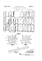
- Figure 1 is a sectional view of a centrifugally molded annular ring made and utilized in carrying out the improved method
- Fig. 2 is a diagrammatic plan view of a roller table and hot saw for severing the ring shown in Fig. 1 to form one or more arcuate blooms, a conveyor, a furnace charging device, a holding furnace, and a stand of grooved rolls, which may be utilized for carrying out the improved method;
- Fig. 3 is a perspective view of an arcuate bloom severed from the ring shown in Fig. 1
- Fig. 4 is an enlarged fragmentary elevation of a three high stand of grooved rolls, which may be utilized for straightening and iihen reducingthe arcuate bloom shown in Fig. 5 is an enlarged section through the arcuate bloom shown in Fig. 3;
- Fig. 6 is an enlarged section through the bloom after it has been given a straightening pass on the rolls shown in Fig. 4;
- Fig. 7 is a perspective view of abillet which may be produced from the straightened bloom by reducing the same by a plurality of passes on the rolls shown in Fig. 3;
- Fig. 8 is a perspective view of an arcuate slab which maybe utilized for rolling plates
- Fig. 9 is an enlarged fragmentary elevation of a three high stand of plain rolls, which may be utilized for straightening and/or reducing the arcuate slab shown in Fig. 8;
- Fig. 10 is an enlarged section through the arcuate slab shown in Fig. 8;
- Fig. 11 is an enlarged section through the slab after it has been given a straightening pass on the rolls shown in Fig. 9;
- Fig. 12 is a perspective View of a plate
- the preferably continuous annular ring 20 is centrifugally molded by introducing fluid molten metal at a temperature of 2600 F. and upwards into a rapidly rotating annular mold, wherein the molten metal by the action of centrifugal force assumes a ring shape.
- a blanket or coating of heat insulating material is preferably deto control the cooling of different regions of the ring.
- the blanket of the same may adhere to the inner face of the ring after it has been removed from the centrifugal molding machine and severed, as indicated diagrammatically at 31 in Figs. 1 and 3.
- the arcuate blooms 23 are conveyed by a conveyor 32 from the roller table 21 to the charging end of the holding furnace 34, where a furnace charging device 35 may be utilized for charging them into the furnace 34.
- the arcuate blooms 23 are heated to the desired rolling temperature in the holding I surfaces 24 and 25 are engaged by the rolls to compress the blooms between the opposite non-parallel surfaces and thereby straighten the blooms as they issue from the rolls.
- the mill 36 may comprise grooved rolls shown more or less diagrammatically in Fig. 4 in which the straightening pass is indicated generally at 37.
- a cross section through the arcuate bloom is shown in Fig. 5 immediately before the bloom is passed through the straightening pass 37, while Fig. 6 shows a cross section of the straightened bloom after it issues from the straightening pass 37.
- the roll pass 37 is designed so that the upper and lower surfaces 24 and 25 of the bloom are not only compressed by the pressure applied thereto by the rolls, but they are also depressed as indicated diagrammatically at 24a and 25a in Fig. 6, so that the concaved arcuate surface 27-29 of the arcuate bloom is displaced and extruded outward to remove the concavity during the straightening pass as indicated diagrammatically at 2911 in Fig.
- the displacement of the metal at and adj acent the concaved surface 29 likewise loosens or cracks away any insulating material which may have adhered to that surface, so as to avoid the necessity of performing a major cleaning operation to remove the heat insulating material; and the straightening roll pass 37 also removes the sharp corners 30 so that the straightened bloom 236 shown in Fig. 6 has rounded corners 28a.
- the straightened bloom 23b may then be given a desired number of passes through the grooved rolls shown in Fig. 4 to produce billets 38 of any desired size, such as shown in Fig. 7.
- the ring When it is desired to roll plates, the ring may be molded so that arcuate slabs such as shown at 40 in Fig. 8 may be severed from the ring, which may be straightened and rolled on the mill 36 which may comprise plain rolls shown at 41 in Fig. 9.
- a cross section through the arcuate slab 40 is shown in Fig. 10 immediately before the slab is given a straightening pass through the rolls 41, while Fig. 11 shows a cross section of the straightened slab 40a after it issues from the straightening pass.
- the arcuate slab 40 not only has its upper and lower non-parallel surfaces engaged by and compressed by the pressure applied thereto by the rolls 41, but the arcuate surface 40- thereof, which may be very slightly concaved, is displaced and extruded to remove the concavity during the straightening pass, as indicated diagrammatically at 40a in Fig. 11.
- the displacement of the metal at and adjacent to the concave surface 40' likewise loosens or cracks away any insulating material which may have adhered to that surface following the centrifugal molding operation.
- the straightened bloom 40a may then be given a desired number of passes through the rolls 41 to produce plates 42 of any desired size, such as shown in Fig. 12.
- the rings 20, having cross sections for being severed to produce either the arcuate blooms 23 or the arcuate slabs 40 preferably have a cross sectional area of some sixteen square inches and a circumferential length of some twenty-five feet. However, when it is desired to produce larger blooms, slabs, billets and the like, the rings 20 may be molded to have larger crosssectional areas and /or circumferential lengths.
- the improved method which includes centrifugally molding an annular' ring having a generally trapezoidal cross section, severing the ring to form one or more arcuate blooms, then compressing and roll straightening the arcuate blooms by applying pressure to the non-parallel surfaces thereof, and then reducing the straightened blooms to form products of the desired size, a high quality product is produced, devoid of defects, by a minimum number of rolling operations at a minimum cost.
- the method of making massive metal blooms, slabs, billets and the like which includes centrifugally molding an annular ring having non-parallel annular surfaces, severing the ring to form arcuate blooms having a substantially trapezoidal shape in cross section with opposite non-parallel surfaces, and then straightening the arcuate blooms by passing the same through rolls engaging the non-parallel surfaces and compressingand displacing the metal between said surfaces.
- the method of making massive metal blooms, slabs, billets and the like which includes centrifugally molding an annular ring with an insulating material coating on its inner-arcuate surface, said ring having nonparallel annular surfaces, severing the ring to form arcuate blooms having opposite arcuate surfaces and opposite non-parallel surfaces, the inner arcuate surface of the blooms havinginsulating material adhering thereto, and then rolling the non-parallel surfaces and compressing the arcuate blooms by pressure applied to said non-parallel surfaces to displace the metal at and adjacent to said last mentioned arcuate surface to loosen the material adhering thereto and to straighten the blooms.
- the method of making massive metal blooms, slabs, billets and the like which includes centrifugally molding an annular ring having non-parallel annular surfaces, severing the ring to form arcuate blooms having opposite arcuate surfaces and opposite nonparallel surfaces, the blooms having sharp corners between the non-parallel surfaces and one of the arcuate surfaces, and then rolling the non-parallel surfaces and compressing the arcuate blooms between said non-parallel surfaces to extrude the metal at and adjacent to the said sharp corners to eliminate the same and straighten the blooms.
- the method of making massive blooms, slabs, billets and the like which includes centrifugally molding an annular ring having non-parallel annular surfaces, severing the ring to form arcuate blooms having opposite arcuate surfaces and opposite non-parallel surfaces, one of the arcuate surfaces being slightly concaved between the parallel surfaces and the corners between said arcuate sharp, and then rolling the non-parallel sur faces and compressing the arcuate blooms between said non-parallel surfaces to extrude the metal at and adjacent to the said concaved surface and sharp corners to eliminate the concavity and sharp corners and straighten the blooms.
- the method of making metal billets, plates and the like which includes centrifugally molding an annular ring having nonparallel annu lar surfaces, severing the ring to form an arcuate bloom having opposite arcuate surfaces and opposite non-parallel surfaces, then straightening the arcuate bloom by passing the same through rolls engaging and applying pressure to the nonparallel surfaces, and then rolling the straightened bloom by a plurality of passes to form billets, plates and the like.
Landscapes
- Engineering & Computer Science (AREA)
- Mechanical Engineering (AREA)
- Metal Rolling (AREA)
Description
y 9, 1933- H. M. NAUGLE ET AL 1,903,171
MAKING BLQOMS, SLABS, AND BILLETS Filed April7,- 1952 5 Sheets- Sheet l IIIII gwuentou A J i'mwselzd y 9, 1933- H. M. NAUGLE ET AL. 1,908,171
TIT.-
A. J lbw/Mend x ww H. M. NAUGLE ET AL 1,908,171
MAKING BLOOMS, SLABS, AND BILLETS Filed April'7, 1932 5 Sheets-Sheet 3 HMNaugle A. J. Ibznzsend Fly/2 outer peripheral area thereof.
Patented May 9, 1933 UNITED STATES PATENT OFFICE HARRY M. NAUGLE AND ARTHUR J. TOWNSEND, OF CANTON, OHIO, ASSIGNORS TO NAUGLE & TOWNSEND, INC., OF WILMINGTON, DELAWARE, A. CORPORATION OF DELAWARE Application filed April 7,
The invention relates to the centrifugal molding, straightening and rolling of steel blooms, slabs, billets and the like; and this application is a continuation in part of the common subject matter of our copending application, Serial No. 448,602, filed April 30,
1930, entitled Making blooms, slabs and billets.
One of the objects of the present improvements is to make an annular ring by centrifugally molding molten metal to form a ring with such an external shape or configuration that when the ring is severed to form one or more arcuate blooms, and the blooms are given a roll pass through a stand of plain or grooved rolls, straightened blooms, slabs or billets issue from the rolls.
It is a further object of the present invention to make a molded annular ring having a thickness at its inner circumference sufliciently greater than the thickness at its outer circumference, that the inner peripheral area of the ring is substantially the same as the Another ob 'ect of the present invention is to centrifugally mold an annular ring, sever the ring to formoneor more arcuate blooms, and then straighten the arcuate blooms, by pressure rolling and compressing the metal between rolls engaging the upper and lower surfaces of the blooms as distinguishedfrom the arcuate surfaces thereof.
A further object of the present invention is to centrifugally mold an annular ring, sever the ring to form one or more arcuate blooms having opposite arcuate surfaces and opposite non-parallel surfaces, then straighten the arcuate blooms by rolling the same to compress the blooms between the opposite non-parallel surfaces, and then reduce the straightened blooms to form billets or slabs.
The centrifugal molding of the annular rings may be carried out by utilizing the method of making blooms, slabs and billets disclosed in our copending application, Serial No. 465,303, filed July 2, 1930, and the rate of cooling and solidification of different portions or regions of the ring may be controlled by applying a blanket of heat insulating material to the inner face of the ring, as
MAKING BLOOMS, SLABS, AND BILLETS 1932. Serial No. 603,764.
from the arcuate face of the arcuate bloom. I I
It is thereforea further object of the present invention to straighten an arcuate bloom having opposite arcuate surfaces and opposite non-parallel surfaces, which may have insulating material adhering to one of its arcuate surfaces, by pressure rolling the arcuate bloom to apply pressure to the non-pan allel surfaces so as to displace the metal at and adjacent to the said arcuate surface, so that any heat insulating material, which may be adhering thereto cracks or drops away from the bloom, or is loosened so that it is subsequently very easily removed therefrom by a simple or minor cleaning operation.
The inner annular or arcuate surface of a centrifugally molded ring may sometimes be slightly concaved from the upper to the lower surfaces thereof, and the upper and lower inner annular corners of the ring may sometimes be sharp. Preparatory to carrying out roll reducing operations, it is desirable, if not necessary, to eliminate the concavity in the arcuate face of arcuate blooms severed from such rings and to eliminate sharp corners from the blooms.
It is therefore a further object of the present invention to straighten an arcuate bloom.
having opposite arcuate surfaces and opposite non-parallel surfaces, in-which one of the arcuate surfaces may be slightly concaved between the opposite non-parallel surfaces and in which the corners between said arcuate surface and the non-parallel surfaces may be sharp, by pressure rolling the arcuate blooms .to apply pressure to the non-parallel surfaces and displace or extrude the metal in the bloom at and adjacent to its depressed arcuate surface and sharp corners for eliminating the depression or concavity and sharp corposited on the inner face of the rotating ring ners.
And finally, it is an object of the present invention to provide a simplified, inexpensive and convenient method of making blooms, slabs, billets and the like,which eliminates many usual steps or operations carried out in prevailing practice.
These and other objects may be obtained by carrying out the improved method disclosed herein and illustrated diagrammatically in the accompanying drawings forming part hereof, in which Figure 1 is a sectional view of a centrifugally molded annular ring made and utilized in carrying out the improved method;
Fig. 2 is a diagrammatic plan view of a roller table and hot saw for severing the ring shown in Fig. 1 to form one or more arcuate blooms, a conveyor, a furnace charging device, a holding furnace, and a stand of grooved rolls, which may be utilized for carrying out the improved method;
Fig. 3 is a perspective view of an arcuate bloom severed from the ring shown in Fig. 1
Fig. 4 is an enlarged fragmentary elevation of a three high stand of grooved rolls, which may be utilized for straightening and iihen reducingthe arcuate bloom shown in Fig. 5 is an enlarged section through the arcuate bloom shown in Fig. 3;
Fig. 6 is an enlarged section through the bloom after it has been given a straightening pass on the rolls shown in Fig. 4;
Fig. 7 is a perspective view of abillet which may be produced from the straightened bloom by reducing the same by a plurality of passes on the rolls shown in Fig. 3;
Fig. 8 is a perspective view of an arcuate slab which maybe utilized for rolling plates;
Fig. 9 is an enlarged fragmentary elevation of a three high stand of plain rolls, which may be utilized for straightening and/or reducing the arcuate slab shown in Fig. 8;
Fig. 10 is an enlarged section through the arcuate slab shown in Fig. 8;
Fig. 11 is an enlarged section through the slab after it has been given a straightening pass on the rolls shown in Fig. 9; and
Fig. 12 is a perspective View of a plate,
which may be produced from the straightened slab by reducing the same by a plurality asses on the rolls shown in Fig. 9. imilar numerals refer to similar parts throughout the drawings.
In carrying out the improved method, the preferably continuous annular ring 20 is centrifugally molded by introducing fluid molten metal at a temperature of 2600 F. and upwards into a rapidly rotating annular mold, wherein the molten metal by the action of centrifugal force assumes a ring shape. Immediately thereafter, a blanket or coating of heat insulating material is preferably deto control the cooling of different regions of the ring.
After the centrifugal molding of the ring has been completed, the same is removed from the mold and transferred to thelroller table,
21 for being severed by the hot saw 22 to shown at 29 between the upper and lower surfaces 24 and 25, and may also have sharpcorners 30 between the inner concaved arcuate surface 27-29 and the upper and lower surfaces 24 and 25.
When certain types of heat insulating materials are utilized for forming a heat insulating blanket on the inner arcuate face of a centrifugally molded ring, the blanket of the same may adhere to the inner face of the ring after it has been removed from the centrifugal molding machine and severed, as indicated diagrammatically at 31 in Figs. 1 and 3.
The arcuate blooms 23 are conveyed by a conveyor 32 from the roller table 21 to the charging end of the holding furnace 34, where a furnace charging device 35 may be utilized for charging them into the furnace 34. The arcuate blooms 23 are heated to the desired rolling temperature in the holding I surfaces 24 and 25 are engaged by the rolls to compress the blooms between the opposite non-parallel surfaces and thereby straighten the blooms as they issue from the rolls. When itis desired to roll billets from the blooms, the mill 36 may comprise grooved rolls shown more or less diagrammatically in Fig. 4 in which the straightening pass is indicated generally at 37. A cross section through the arcuate bloom is shown in Fig. 5 immediately before the bloom is passed through the straightening pass 37, while Fig. 6 shows a cross section of the straightened bloom after it issues from the straightening pass 37.
The roll pass 37 is designed so that the upper and lower surfaces 24 and 25 of the bloom are not only compressed by the pressure applied thereto by the rolls, but they are also depressed as indicated diagrammatically at 24a and 25a in Fig. 6, so that the concaved arcuate surface 27-29 of the arcuate bloom is displaced and extruded outward to remove the concavity during the straightening pass as indicated diagrammatically at 2911 in Fig.
The displacement of the metal at and adj acent the concaved surface 29 likewise loosens or cracks away any insulating material which may have adhered to that surface, so as to avoid the necessity of performing a major cleaning operation to remove the heat insulating material; and the straightening roll pass 37 also removes the sharp corners 30 so that the straightened bloom 236 shown in Fig. 6 has rounded corners 28a.
The straightened bloom 23b may then be given a desired number of passes through the grooved rolls shown in Fig. 4 to produce billets 38 of any desired size, such as shown in Fig. 7.
When it is desired to roll plates, the ring may be molded so that arcuate slabs such as shown at 40 in Fig. 8 may be severed from the ring, which may be straightened and rolled on the mill 36 which may comprise plain rolls shown at 41 in Fig. 9. A cross section through the arcuate slab 40 is shown in Fig. 10 immediately before the slab is given a straightening pass through the rolls 41, while Fig. 11 shows a cross section of the straightened slab 40a after it issues from the straightening pass.
The arcuate slab 40 not only has its upper and lower non-parallel surfaces engaged by and compressed by the pressure applied thereto by the rolls 41, but the arcuate surface 40- thereof, which may be very slightly concaved, is displaced and extruded to remove the concavity during the straightening pass, as indicated diagrammatically at 40a in Fig. 11.
The displacement of the metal at and adjacent to the concave surface 40' likewise loosens or cracks away any insulating material which may have adhered to that surface following the centrifugal molding operation.
The straightened bloom 40a may then be given a desired number of passes through the rolls 41 to produce plates 42 of any desired size, such as shown in Fig. 12.
The rings 20, having cross sections for being severed to produce either the arcuate blooms 23 or the arcuate slabs 40, preferably have a cross sectional area of some sixteen square inches and a circumferential length of some twenty-five feet. However, when it is desired to produce larger blooms, slabs, billets and the like, the rings 20 may be molded to have larger crosssectional areas and /or circumferential lengths.
In carrying out the improved method, which includes centrifugally molding an annular' ring having a generally trapezoidal cross section, severing the ring to form one or more arcuate blooms, then compressing and roll straightening the arcuate blooms by applying pressure to the non-parallel surfaces thereof, and then reducing the straightened blooms to form products of the desired size, a high quality product is produced, devoid of defects, by a minimum number of rolling operations at a minimum cost.
In the appended claims the expression blooms, slabs, billets and the like is intended to include similar products such as plates and the like; the'eXpression arcuate blooms is intended to include arcuate slabs; and the expression arcuate bloom is intended to include an arcuate slab.
We claim 1. The method of making massive metal blooms, slabs, billets-and the like which includes centrifugally molding an annular ring having non-parallel annular surfaces, severing the ring to form arcuate blooms having opposite arcuate surfaces and opposite nonparallel surfaces, and then straightening the arcuate blooms by passing the same through rolls engaging and applying pressure to the non-parallel surfaces.
2. The method of making massive metal blooms, slabs, billets and the like which includes centrifugally molding an annular ring having non-parallel annular surfaces, severing the ring to form arcuate blooms having a substantially trapezoidal shape in cross section with opposite non-parallel surfaces, and then straightening the arcuate blooms by passing the same through rolls engaging the non-parallel surfaces and compressingand displacing the metal between said surfaces.
3. The method of making massive metal blooms, slabs, billets and the like, which includes centrifugally molding an annular ring with an insulating material coating on its inner-arcuate surface, said ring having nonparallel annular surfaces, severing the ring to form arcuate blooms having opposite arcuate surfaces and opposite non-parallel surfaces, the inner arcuate surface of the blooms havinginsulating material adhering thereto, and then rolling the non-parallel surfaces and compressing the arcuate blooms by pressure applied to said non-parallel surfaces to displace the metal at and adjacent to said last mentioned arcuate surface to loosen the material adhering thereto and to straighten the blooms.
4. The method of making massive metal blooms, slabs, billets and the like which ini cludes centrifugally molding an annular ring having non-parallel annular surfaces, severing the ring to form. arcuate blooms having opposite arcuate surfaces and opposite nonparallel surfaces, one of the arcuate surfaces being slightly concaved between the non-parallel surfaces, and then rolling the non-parsurface and non-parallel surfaces being allel surfaces and compressing the arcuate blooms between said non-parallel surfaces to extrude the metal at and adjacent to the said concaved arcuate surface to eliminate theconcavity and straighten the blooms.
5. The method of making massive metal blooms, slabs, billets and the like which includes centrifugally molding an annular ring having non-parallel annular surfaces, severing the ring to form arcuate blooms having opposite arcuate surfaces and opposite nonparallel surfaces, the blooms having sharp corners between the non-parallel surfaces and one of the arcuate surfaces, and then rolling the non-parallel surfaces and compressing the arcuate blooms between said non-parallel surfaces to extrude the metal at and adjacent to the said sharp corners to eliminate the same and straighten the blooms.
6. The method of making massive blooms, slabs, billets and the like which includes centrifugally molding an annular ring having non-parallel annular surfaces, severing the ring to form arcuate blooms having opposite arcuate surfaces and opposite non-parallel surfaces, one of the arcuate surfaces being slightly concaved between the parallel surfaces and the corners between said arcuate sharp, and then rolling the non-parallel sur faces and compressing the arcuate blooms between said non-parallel surfaces to extrude the metal at and adjacent to the said concaved surface and sharp corners to eliminate the concavity and sharp corners and straighten the blooms.
7. The method of making metal billets, plates and the like which includes centrifugally molding an annular ring having nonparallel annu lar surfaces, severing the ring to form an arcuate bloom having opposite arcuate surfaces and opposite non-parallel surfaces, then straightening the arcuate bloom by passing the same through rolls engaging and applying pressure to the nonparallel surfaces, and then rolling the straightened bloom by a plurality of passes to form billets, plates and the like.
8. The method of making massive blooms, slabs, billets and the like which includes centrifugally molding an annular ring having non-parallel annular surfaces, severing the ring to form an arcuate bloom having opposite arcuate surfacesand opposite non-parallel surfaces, and then straightening the arcuate bloom by passing the same through rolls engaging and applying pressure to the non-parallel surfaces.
9. The method of making metal billets, plates and the like which includes centrifugally molding an annular ring having nonparallel annular surfaces, severing the ring to form arcuate blooms having opposite arcuate surfaces and opposite non-parallel surfaces, then straightening the arcuate blooms have hereunto subscribed our names.
HARRY M. NAUGLE. ARTHUR J TOWNSEND.
Priority Applications (1)
| Application Number | Priority Date | Filing Date | Title |
|---|---|---|---|
| US603764A US1908171A (en) | 1932-04-07 | 1932-04-07 | Making blooms, slabs, and billets |
Applications Claiming Priority (1)
| Application Number | Priority Date | Filing Date | Title |
|---|---|---|---|
| US603764A US1908171A (en) | 1932-04-07 | 1932-04-07 | Making blooms, slabs, and billets |
Publications (1)
| Publication Number | Publication Date |
|---|---|
| US1908171A true US1908171A (en) | 1933-05-09 |
Family
ID=24416810
Family Applications (1)
| Application Number | Title | Priority Date | Filing Date |
|---|---|---|---|
| US603764A Expired - Lifetime US1908171A (en) | 1932-04-07 | 1932-04-07 | Making blooms, slabs, and billets |
Country Status (1)
| Country | Link |
|---|---|
| US (1) | US1908171A (en) |
Cited By (3)
| Publication number | Priority date | Publication date | Assignee | Title |
|---|---|---|---|---|
| US3174221A (en) * | 1960-12-20 | 1965-03-23 | Oregon Metallurgical Corp | Process for making sheet from brittle metals |
| US3218705A (en) * | 1961-11-29 | 1965-11-23 | St Louis Diecasting Corp | Method of making a seal retainer, or the like |
| DE1758008B1 (en) * | 1968-03-20 | 1971-04-22 | Hox Hans Werner | Process for the production of multilayer metals |
-
1932
- 1932-04-07 US US603764A patent/US1908171A/en not_active Expired - Lifetime
Cited By (3)
| Publication number | Priority date | Publication date | Assignee | Title |
|---|---|---|---|---|
| US3174221A (en) * | 1960-12-20 | 1965-03-23 | Oregon Metallurgical Corp | Process for making sheet from brittle metals |
| US3218705A (en) * | 1961-11-29 | 1965-11-23 | St Louis Diecasting Corp | Method of making a seal retainer, or the like |
| DE1758008B1 (en) * | 1968-03-20 | 1971-04-22 | Hox Hans Werner | Process for the production of multilayer metals |
Similar Documents
| Publication | Publication Date | Title |
|---|---|---|
| US2008626A (en) | Method for manufacturing metallic materials by rotating rolls or wheels containing a molten metal between them | |
| JP2738934B2 (en) | Method and apparatus for manufacturing steel strip | |
| US4565240A (en) | Method and apparatus for continuous casting of metal sheet | |
| US1908171A (en) | Making blooms, slabs, and billets | |
| CN106424137A (en) | Zero-broadside magnesium alloy board rolling method and apparatus used in method | |
| US3374826A (en) | Process for continuously casting elongated metal bodies | |
| CN106345812A (en) | Rolling method for magnesium alloy sheet material with side pressure and adopted device thereof | |
| US1865443A (en) | Method and apparatus for continuous casting of steel billets | |
| US3766962A (en) | Method of continuously casting a slab | |
| US1607475A (en) | Manufacture of seamless tubing | |
| US3837391A (en) | Continuous casting apparatus | |
| US3650314A (en) | Apparatus for manufacturing stretch-formed products of high-melting metals | |
| US1938257A (en) | Production of hollow ingots | |
| US3078696A (en) | Plunger for forming glass articles | |
| US1882516A (en) | Making blooms, slabs and billets | |
| US2280783A (en) | Rolling internally flanged annuli | |
| CN210817368U (en) | Equipment for eliminating edge black line defect of large-width steel plate rolled material | |
| US3425254A (en) | Rolling of slabs | |
| CN212350284U (en) | High section of thick bamboo aluminum alloy ring system base device | |
| US2333286A (en) | Apparatus for casting | |
| JP2992364B2 (en) | Continuous casting method and continuous casting apparatus for annular steel products | |
| US3437129A (en) | Apparatus for continuously casting elongated metal bodies | |
| US1991486A (en) | Process for rolling rings | |
| US2343771A (en) | Method of making composite billets | |
| US3024528A (en) | Method of premoving surface defects in ingots |