US1908165A - Overhead door construction - Google Patents
Overhead door construction Download PDFInfo
- Publication number
- US1908165A US1908165A US479683A US47968330A US1908165A US 1908165 A US1908165 A US 1908165A US 479683 A US479683 A US 479683A US 47968330 A US47968330 A US 47968330A US 1908165 A US1908165 A US 1908165A
- Authority
- US
- United States
- Prior art keywords
- post
- door
- tracks
- track
- posts
- Prior art date
- Legal status (The legal status is an assumption and is not a legal conclusion. Google has not performed a legal analysis and makes no representation as to the accuracy of the status listed.)
- Expired - Lifetime
Links
- 238000010276 construction Methods 0.000 title description 6
- 101100379079 Emericella variicolor andA gene Proteins 0.000 description 1
- 235000014443 Pyrus communis Nutrition 0.000 description 1
- 230000000717 retained effect Effects 0.000 description 1
Images


Classifications
-
- E—FIXED CONSTRUCTIONS
- E06—DOORS, WINDOWS, SHUTTERS, OR ROLLER BLINDS IN GENERAL; LADDERS
- E06B—FIXED OR MOVABLE CLOSURES FOR OPENINGS IN BUILDINGS, VEHICLES, FENCES OR LIKE ENCLOSURES IN GENERAL, e.g. DOORS, WINDOWS, BLINDS, GATES
- E06B3/00—Window sashes, door leaves, or like elements for closing wall or like openings; Layout of fixed or moving closures, e.g. windows in wall or like openings; Features of rigidly-mounted outer frames relating to the mounting of wing frames
- E06B3/01—Removable or disappearing walls for hangars or other halls, e.g. for aircraft
-
- Y—GENERAL TAGGING OF NEW TECHNOLOGICAL DEVELOPMENTS; GENERAL TAGGING OF CROSS-SECTIONAL TECHNOLOGIES SPANNING OVER SEVERAL SECTIONS OF THE IPC; TECHNICAL SUBJECTS COVERED BY FORMER USPC CROSS-REFERENCE ART COLLECTIONS [XRACs] AND DIGESTS
- Y10—TECHNICAL SUBJECTS COVERED BY FORMER USPC
- Y10S—TECHNICAL SUBJECTS COVERED BY FORMER USPC CROSS-REFERENCE ART COLLECTIONS [XRACs] AND DIGESTS
- Y10S292/00—Closure fasteners
- Y10S292/36—Overhead door latches
Definitions
- This invention relates to improvements in overhead door construction in which a series of doors arev separated by removable posts whereby, Whenthe doors are open, the vposts can' be removed to one side or the other, clearing the entire door space.
- Fig: 1 is a front elevation view of aibuilding having/a broad door opening extending substantially the width of the bullding wlth a series of posts dividing the same into doorways for the operation of single door sections or single vseparate doors.
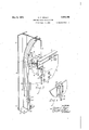
- Fig. 2 is an enlarged detail of the structure appearing in Fig. 1 taken from the inside of the buildin ,-being substantlall'y in section on line 2,-2 o Fig. 4, the samey being shown in broken sections.l
- Fig. 3 ⁇ is an enlarged ⁇ detail perspective of one of the posts, the transverse track and the lock means for the, door in their operative position, one ot the door lock latches being shown by dotted lines.
- f 0 Fig. 4 is an enlarged detail vertical section al view taken on linut-4 of Figs. 1 and 2,..
- Fig. 5 is an enlarged detail sectional elevay tion view taken on line 5--5 of Fig. 2, showing the position of the door locking latch when A the door is in elevated or openposition.
- 1, 1 are the side frames or door jambe of the broad door opening.
- 2 is the top frame of the entire doorway.
- 3, 3 are the removoverhead doors 4', suc as those illustrated at the left of Fig.'1, one door being entirely closed and the other partially open, the doors to the right being. entirely open.
- the doors '4 are flexible doors made up of a series lof horizontal panels hinged together so that they can travel in the vertical track 5, thence into the curved portion of track 6, and then into the horizontal portion 7 above, the parts being indicated particularly in Fig. 4.
- a guide roller 41 is secured to each door panel section and projects to travel in the said tracks in the well-known manner of the door known as the overhead door.
- Each ldoor post ⁇ is made up of a pair of uprightf angle bars 31. These are held in spaced re'- ⁇ lation at' the top by plate 8 which projects inwardly from the posts into the building.
- a yfront plate 9 is secured to'the lforward edge of the plate 8 by a pair of angle brackets 91. The plate 9 is adjustable thereon by bolts 92 in the slots 93, see particularly Fig. 3.
- a pair of outwardly projecting rollers 10 are carried on journal pins 101 fon plate ,9 and are disposed in the inclined cross track ⁇ 11 which is carried on fixedparts above to be later described.
- This track is a very little j higher at the end toward which the4 disconnected posts are moved so that in movingithe' posts'they will clear the floor.
- each post is provided with a stop plate 14, see Figs. 43 and 6, secured to the plate 8 and adapted to contact with one side of the lower edge of upper plate post in working position.
- latch bolt 15 On the opposite side of plate 8 is disposed latch bolt 15, suitably supported. to move into position and retain the post definitely in place.
- a vertically operating lock bolt 16 is guided between the lower ends of the angle plates 31 constituting the' post.
- Underneath the post is a floor plate 17 with a central slot or socket 172 to receive the lower end of thebolt 16.
- This floor plate 17 is provided with a stop rib 171 to receive and guide the ⁇ lower end of the post.
- the bolt 16 is provided with a perforated ear 1.61, and the lower end of bolt 15 is provided with an eye 151.
- a cir' cular pivoted actuating plate18 with handle 181 is pivotedat 182 on the inner side of each post.
- Links 162 extend upwardly from the bolts 16 to one side of this operating plate 18.
- Links 152 extend down from the eye,151 on the bolt 15 to the opposite side of the disk 18.
- This clearance can, of course, be accomplished by making the edges of the plates 13 successively ofslightly different ⁇ relative height, but the extent of the engagement is so small that this provision is not a necessity, the swinging of the lower ends of the posts being suiicient.
- I provide a pair of pivoted lock latches.19 supported' on rockshaft 191, each with a hookedv engagingv end 192 adapted to project through apertures 61 in the track 6.
- I connect spring 20 to the lower end of this latch and the opposite end of the spring to an eye 201 on the bracket 131. This tends to hold the latches always in engagement.
- the transverse track can be used with any sort of attaching and supporting means for the post, although it has special advantages in track might be dispensed with, and. as the posts are not unduly heavy they might be carried by an attendant and inserted in place. This, however, would be a matter of very considerable inconvenience.
- the lever means for operating the bolts at top and bottom simultaneously mightbe'dispensed with but it is very convenient and automatically holds .the bolts in withdrawn position ready to be inserted when the post is set into place. All of this is of advantage.
- an overhead door structure having a flexible door with vertical front and horizontal overhead tracks and curved intermediate tracks, a transverse track supported within the curved intermediate tracks, a' plurality of doors, a removable door post dis posed between the 'said doors and having vertical sections of track adapted to register with the lower ends of the curved tracks, brackets carrying rollers at .the top of said post to travel in the transverse track, post connections above the removable posts to which thel curved tracks are secured, a stop plate on the upper end of the post structureaa lock bolt associated with said stop to engage and lock the upper end of the post in alignment and in place, a lock bolt at the bottom'of the said post, and a rocking pivoted plate carried within the said post between the said bolts and having proper connections thereto y whereby the top and bottom bolts may be operated simultaneously and retained in drawn position.
- an overhead door structure having a flexible door vwith vertical front and horizontal ⁇ overhead tracks and curved intermediate tracks, a transverse track supported within the curved intermediate tracks, a plurality of doors, a removable door post disposed between t-he said doors andA having vertical sections of track adapted to register with the lower ends of the curved tracks, brackets carrying rollers at the top of said post to travel in the transversetrack, post connections above the removablel posts to which the curved tracks are secured, a transi lock the upper end of the post in alignment and in place, and a lock bolt at the bottom ofthe said post.
- an overhead door structure having a flexible door with vertical front and horizontal overhead tracks and curved intermediate tracks, a transverse track supported within the curved intermediate tracks, a plurality of doors, a removable door post disposed between the said doors and having vertical sections of track adapted to register with the lower ends of the curved tracks, brackets carrying rollers at the top of said post to travel in thevtransverse track, post c onnections above the removable 'posts to which the curved tracks are secured, a transposts and within the said curved track, p ivoted lock latches carried by the fixed structure with projecting ends adapted to project through apertures in the said curved verse track suitably supported above the track to provide lock stops for retaining the doors in open position, spring ,means for holding the same yieldingl closnedfa cam formed thereon for actuating the same, a stop plate on the upper end of the post structure adapted to coact with the said pivoted lock latch, and means fory detachably supporting said post.
- An overhead door structure comprising a plurality of flexible doors andvertical and horizontal vtracks and intermediate curved trackstherefor, an intermediate removable post, a pivoted lock on the said curved tracks to hold the doors in open position when the posts are removed, and automatic means disposed to be tripped by said post to actuate said lock when the removable post is replaced.
- An overhead door structure comprising a plurality of ⁇ flexible doors and vertical and horizontal tracks and intermediate curved tracks therefor, an intermediate removable post, and a lock on the said curved tracks to hold the doors in open position' when the removable post is replaced.
Landscapes
- Engineering & Computer Science (AREA)
- Civil Engineering (AREA)
- Structural Engineering (AREA)
- Wing Frames And Configurations (AREA)
Description
c. c. Mom-:R 1,908,165
OVERHEAD DOOR 'CONSTRUCTION Filed Sept. 4, 1930 3 Shees-SheerI l May 9, 1933..
INVENOR BY (Waff/65 6%?? WTTORNEY* May 9, 1933. c. c. MOLER y 1,908,165
OVERHEAD DOOR CONSTRUCTION Fi1ed sept. 4,' 1930 3 shqets-sneet 2 A IToRNEY May 9, 1933.- c. c. MoLER OVERHEAD DOOR CONSTRUCTION Filed Sept. 4, 1930 3 Sheets-Sheet 5 INVENTOR idf/ 1; 6%
- ATTORNEY- Patented May 9,I 1933 UNITED STATES PATENT ori-Ica- CHARLEs C. HOLER, or HARTFORD CITY, INDIANA, AssIeNoR To OVERHEAD Doonl CORPORATION, or' HARTFORD CITY, INDIANA ovERHmD DooR CoNsTRUCT'IoN Implication mea september 4, 1930. y seria; No. 479,683.
This invention relates to improvements in overhead door construction in which a series of doors arev separated by removable posts whereby, Whenthe doors are open, the vposts can' be removed to one side or the other, clearing the entire door space..
The objects of the invention are:
First, to provide such a structure with eiective removable door posts. A
Second, to provide improved locking means for retaining said door posts in place.
Third, to provide improved locking means to prevent4 the closing of the doors when the posts are removed.,
l5 Fourth, to provide improved transverse track and transporting means for transporting such posts to the side of the door. Objects pertaining to details and economies of construction and operation will ap- *0 pear from the\description to follow. A preferred embodiment of my invention is ilustrated in the accompanying, drawings, in which:
Fig: 1 is a front elevation view of aibuilding having/a broad door opening extending substantially the width of the bullding wlth a series of posts dividing the same into doorways for the operation of single door sections or single vseparate doors. v
Fig. 2 is an enlarged detail of the structure appearing in Fig. 1 taken from the inside of the buildin ,-being substantlall'y in section on line 2,-2 o Fig. 4, the samey being shown in broken sections.l
Fig. 3` is an enlarged `detail perspective of one of the posts, the transverse track and the lock means for the, door in their operative position, one ot the door lock latches being shown by dotted lines. f 0 Fig. 4 is an enlarged detail vertical section al view taken on linut-4 of Figs. 1 and 2,..
showing the details of the upper ends of the posts and the supporting and transporting means, and the lock means for holding thev 5 door in open position.
' .able posts which carr 4the vertical' tracks for Fig. 5 is an enlarged detail sectional elevay tion view taken on line 5--5 of Fig. 2, showing the position of the door locking latch when A the door is in elevated or openposition.
Fig. Gis an enlarged detail perspective view of the stop and lock latch for the upper end of one of the posts.
The parts will` be identified by their numerals of reference which are the same in all the'views. e
1, 1 are the side frames or door jambe of the broad door opening. 2 is the top frame of the entire doorway. 3, 3, 3 are the removoverhead doors 4', suc as those illustrated at the left of Fig.'1, one door being entirely closed and the other partially open, the doors to the right being. entirely open. The doors '4 are flexible doors made up of a series lof horizontal panels hinged together so that they can travel in the vertical track 5, thence into the curved portion of track 6, and then into the horizontal portion 7 above, the parts being indicated particularly in Fig. 4.
A guide roller 41 is secured to each door panel section and projects to travel in the said tracks in the well-known manner of the door known as the overhead door., Each ldoor post` is made up of a pair of uprightf angle bars 31. These are held in spaced re'-` lation at' the top by plate 8 which projects inwardly from the posts into the building. A yfront plate 9 is secured to'the lforward edge of the plate 8 by a pair of angle brackets 91. The plate 9 is adjustable thereon by bolts 92 in the slots 93, see particularly Fig. 3. j A pair of outwardly projecting rollers 10 are carried on journal pins 101 fon plate ,9 and are disposed in the inclined cross track `11 which is carried on fixedparts above to be later described. This track is a very little j higher at the end toward which the4 disconnected posts are moved so that in movingithe' posts'they will clear the floor.
Fixed post members 12 corresponding to 90."
. inches for the width of an the angle bars 31, 31 are secured to the wall and are provided with supporting plate 1.3, corresponding to the plate 8 below. To this plate 13 are secured the curved portions of track 6, in the same relations as the vertical tracks 5 below, the lower ends thereof registering with the tracks 5 on the posts when the posts are in operative position. Transverse track 11 is secured to the plates 13 by angle brackets 131 in the inclined relation previously referred to. The incline is about two eight foot door. It will thus be seen that when the posts are released they can be removed along the track to the side of the doorway within the return wall and as many posts accommodated as space permits or as the door opening requires. I
The upper end of each post is provided with a stop plate 14, see Figs. 43 and 6, secured to the plate 8 and adapted to contact with one side of the lower edge of upper plate post in working position. On the opposite side of plate 8 is disposed latch bolt 15, suitably supported. to move into position and retain the post definitely in place. A vertically operating lock bolt 16 is guided between the lower ends of the angle plates 31 constituting the' post. Underneath the post is a floor plate 17 with a central slot or socket 172 to receive the lower end of thebolt 16. This floor plate 17 is provided with a stop rib 171 to receive and guide the `lower end of the post. The bolt 16 is provided with a perforated ear 1.61, and the lower end of bolt 15 is provided with an eye 151. A cir' cular pivoted actuating plate18 with handle 181 is pivotedat 182 on the inner side of each post. Links 162 extend upwardly from the bolts 16 to one side of this operating plate 18. Links 152 extend down from the eye,151 on the bolt 15 to the opposite side of the disk 18. It will thus be seen thatwhen the disk is moved to the position seen, at the left of Fig. 2, where the post has been released, both of these latch bolts have been withdrawn so that the post can be moved freely along the track When the post is in position, as seen at the right hand of Fig. 2, the lever is moved to a position at right angles to that appearing at the left and the bolts'a-re forced into engagement and retain the posts effectively in place. The action of these bolts could ofcourse be accentuated by springs but it is not necessary. The actuating means is like that often used for door bolts.
iBecause of the incline of the track 11 as above pointed out, the lower ends of the posts clear the floor until they'y are moved to their articular location. Because of this fact, t e lower ends of the postsv can swingy laterally of the supporting track 11 and into the room or building closed by the door, pivoting on their supporting wheels 10 in their 13 to secure the alignment of the door tracks 11, as seen in cross section in Fig. 4, and thus permitting the clearance of the upper ends of the plates 14 until the posts slide down to their'particular positions, when the upper end of plate 14 will engage the corre-` sponding plate 13 and the latch 15` may be permitted to engage.
This clearance can, of course, be accomplished by making the edges of the plates 13 successively ofslightly different` relative height, but the extent of the engagement is so small that this provision is not a necessity, the swinging of the lower ends of the posts being suiicient.
It will be very clear that when the doors are open under these circumstances and the posts removed, it would be a very serious matter if anyone should close one of the doors. It would drop down out of the ,curved tracks 6 and it might not be very readily replaced. At any rate the swinging door would be highly undesirable. I therefore provide automatic means for locking and retaining each open door in elevated position when the post is removed. s
To accomplish this I provide a pair of pivoted lock latches.19 supported' on rockshaft 191, each with a hookedv engagingv end 192 adapted to project through apertures 61 in the track 6. I connect spring 20 to the lower end of this latch and the opposite end of the spring to an eye 201 on the bracket 131. This tends to hold the latches always in engagement. The lower end of the left hand latch 19` I oii'set at 193, providing the same with a beveled cam surface disposed to be contacted with the outer edge of the vstop plate 14 on the removable post, so post is forced into position the edge of stop plate 14slides along the bevel 193 and cams and forces the lower end of the latch outwardly, withdrawing the engaging locking portion 192 from the track 6.
Thus it will be seen that automatically, when the door post is removed, land it can only be removed when the door is open, the lock latch 19 swings to position and locks the door in open position. This structure can be varied greatly in detail. The transverse track can be used with any sort of attaching and supporting means for the post, although it has special advantages in track might be dispensed with, and. as the posts are not unduly heavy they might be carried by an attendant and inserted in place. This, however, would be a matter of very considerable inconvenience.
The lever means for operating the bolts at top and bottom simultaneously mightbe'dispensed with but it is very convenient and automatically holds .the bolts in withdrawn position ready to be inserted when the post is set into place. All of this is of advantage.
Separate and distinct locks might be prethat when the lll the arrangement here shown. The
pared for locking the doors open, but it is far better to have this done automatically.
Having ythus described 'my invention what I claim as new and desire to secure by Letters Patent is:
1. In an overhead door structure having a flexible door with vertical front and horizontal overhead tracks and curved intermediate tracks, a transverse track supported within the curved intermediate tracks, a' plurality of doors, a removable door post dis posed between the 'said doors and having vertical sections of track adapted to register with the lower ends of the curved tracks, brackets carrying rollers at .the top of said post to travel in the transverse track, post connections above the removable posts to which thel curved tracks are secured, a stop plate on the upper end of the post structureaa lock bolt associated with said stop to engage and lock the upper end of the post in alignment and in place, a lock bolt at the bottom'of the said post, and a rocking pivoted plate carried within the said post between the said bolts and having proper connections thereto y whereby the top and bottom bolts may be operated simultaneously and retained in drawn position. f 2. In an overhead door structure having a flexible door with vertical front and horizontal overhead tracks and curved intermediate tracks, a -transverse track supported within the curved intermediate tracks, a plurality of doors, a removable door post dis'- posed between the said doors and having ver? .tical sections of track adapted to register with the lower ends of the curved tracks, brackets carrying rollers at the top of said post to travel in the transverse track, pivoted lock latches carried by the fixed structure with projecting ends adapted to project through apertures in the said curved track to provide lock stops for retaining the doors in open position, spring means for holding the same yieldingly closed, a cam Aformed thereon for actuating the same, a stop plate on the upper end of thepost structure adapted to coact y ,with the said pivoted lock latch, a lock bolt associated with said stop to engage and lock the upper end of the ost in alignment and in place, and a lock bo t at the bottom of the said ost.
3. n an overhead door structure having a flexible door vwith vertical front and horizontal` overhead tracks and curved intermediate tracks, a transverse track supported within the curved intermediate tracks, a plurality of doors, a removable door post disposed between t-he said doors andA having vertical sections of track adapted to register with the lower ends of the curved tracks, brackets carrying rollers at the top of said post to travel in the transversetrack, post connections above the removablel posts to which the curved tracks are secured, a transi lock the upper end of the post in alignment and in place, and a lock bolt at the bottom ofthe said post.
4: In an overhead door structure having a flexible door with vertical front and horizontal overhead tracks and curved intermediate tracks, a transverse track supported within the curved intermediate tracks, a plurality of doors, a removable door post disposed between the said doors and having vertical sections of track adapted to register with the lower ends of the curved tracks, brackets carrying rollers at the top of said post to travel in thevtransverse track, post c onnections above the removable 'posts to which the curved tracks are secured, a transposts and within the said curved track, p ivoted lock latches carried by the fixed structure with projecting ends adapted to project through apertures in the said curved verse track suitably supported above the track to provide lock stops for retaining the doors in open position, spring ,means for holding the same yieldingl closnedfa cam formed thereon for actuating the same, a stop plate on the upper end of the post structure adapted to coact with the said pivoted lock latch, and means fory detachably supporting said post.
5. In an overhead door structure, the combination with a flexible door and tracks therefor, of a removable post, aninclined transverse track disposed and supported beneath the overhead tracks, and a bracket on the said'post having rollers disposed at each side to travel in said transverse track, whereby the post may be transferred to the side of the doorway.
los
6. In an overhead door structure, the comi bination with a flexible door and tracks therefor, 'of a removable post, a transverse track disposed and supported beneath the overhead tracks, and a bracket on the said post having rol-1ers disposed at each side to travel in said transverse track, whereby the post may be transferred to the side of the doorway.
7 An overhead door structure comprising a plurality of flexible doors andvertical and horizontal vtracks and intermediate curved trackstherefor, an intermediate removable post, a pivoted lock on the said curved tracks to hold the doors in open position when the posts are removed, and automatic means disposed to be tripped by said post to actuate said lock when the removable post is replaced.`
removed, and automatic means disposed to be tripped by said post to actuate said lock when the removable post is replaced.
9. An overhead door structure comprising a plurality of` flexible doors and vertical and horizontal tracks and intermediate curved tracks therefor, an intermediate removable post, and a lock on the said curved tracks to hold the doors in open position' when the removable post is replaced.` Y
In witness whereof I have hereunto set my hand.
CHARLES C. MOLER.
Priority Applications (1)
| Application Number | Priority Date | Filing Date | Title |
|---|---|---|---|
| US479683A US1908165A (en) | 1930-09-04 | 1930-09-04 | Overhead door construction |
Applications Claiming Priority (1)
| Application Number | Priority Date | Filing Date | Title |
|---|---|---|---|
| US479683A US1908165A (en) | 1930-09-04 | 1930-09-04 | Overhead door construction |
Publications (1)
| Publication Number | Publication Date |
|---|---|
| US1908165A true US1908165A (en) | 1933-05-09 |
Family
ID=23904980
Family Applications (1)
| Application Number | Title | Priority Date | Filing Date |
|---|---|---|---|
| US479683A Expired - Lifetime US1908165A (en) | 1930-09-04 | 1930-09-04 | Overhead door construction |
Country Status (1)
| Country | Link |
|---|---|
| US (1) | US1908165A (en) |
Cited By (24)
| Publication number | Priority date | Publication date | Assignee | Title |
|---|---|---|---|---|
| US2520524A (en) * | 1946-09-13 | 1950-08-29 | Ajax Cons Company | Blind construction |
| US2738004A (en) * | 1952-01-21 | 1956-03-13 | Overhead Door Corp | Mounting for multiple vertically sliding doors in a single door opening |
| US2979786A (en) * | 1958-08-13 | 1961-04-18 | Youngstown Steel Door Co | Railway box cars |
| US3022817A (en) * | 1958-07-22 | 1962-02-27 | Paschal P Cafardi | Three-way double garage door |
| US3150613A (en) * | 1961-11-13 | 1964-09-29 | Pullman Inc | Post lock for railway cars |
| US3165076A (en) * | 1961-08-02 | 1965-01-12 | Pullman Inc | Door post locking means for open side railway cars or the like |
| US3191549A (en) * | 1961-08-28 | 1965-06-29 | Pullman Inc | Door assembly for open side railway cars |
| US3191548A (en) * | 1961-08-02 | 1965-06-29 | Pullman Inc | Railway car construction |
| US3195615A (en) * | 1963-02-07 | 1965-07-20 | Ray H Neiscwander | Retractable guide post for overhead doors |
| US3217784A (en) * | 1963-02-25 | 1965-11-16 | Frantz Mfg Company | Overhead door construction and removable center post therefor |
| US3811489A (en) * | 1972-10-17 | 1974-05-21 | Acrite Ind Inc | Bifold door system |
| US4871007A (en) * | 1988-09-19 | 1989-10-03 | Strick Corporation | Overhead door construction for providing increased door opening clearance |
| US5022691A (en) * | 1990-08-17 | 1991-06-11 | Whiting Roll-Up Door Mfg. Corp. | Side lock for a roll-up door |
| US5450697A (en) * | 1994-04-19 | 1995-09-19 | Von Duprin, Inc. | Removable cylinder locked mullion assembly |
| US5533561A (en) * | 1992-05-24 | 1996-07-09 | Forehand, Iv; L. Langstroth | Garage door security system |
| FR2729427A1 (en) * | 1995-01-12 | 1996-07-19 | Whiting Roll Up Door Mfg Corp | SIDE LATCH WITH AUTOMATIC LOCK FOR ROLLING MOUNTING DOOR |
| US6076589A (en) * | 1997-01-10 | 2000-06-20 | Horman KG Brockhagen | Articulated overhead gate for particularly small drop heights |
| US20020109359A1 (en) * | 2001-02-09 | 2002-08-15 | Jeff Nodorft | Latch assembly for a sectional door |
| US20070120377A1 (en) * | 2005-11-29 | 2007-05-31 | King Jeff A | Device for reversibly preventing closure of an overhead door |
| US20070240834A1 (en) * | 2006-04-18 | 2007-10-18 | Jozsef Kiss | Displaceable from the opening sectioned door with track supporting post |
| US20100043506A1 (en) * | 2006-09-19 | 2010-02-25 | Jan Stendal | locking device, a locking arrangement,and a locking system |
| US20130088025A1 (en) * | 2011-10-07 | 2013-04-11 | CIW Enterprises | Self-Engaging Emergency Egress Lock Assembly |
| CN103075077A (en) * | 2013-01-31 | 2013-05-01 | 江苏金秋竹集团有限公司 | Upper folding door of garage |
| FR3126931A1 (en) * | 2021-09-16 | 2023-03-17 | Jean Chereau Sas | Bodywork of a road vehicle for transporting goods provided with a manually operated sliding closing curtain |
-
1930
- 1930-09-04 US US479683A patent/US1908165A/en not_active Expired - Lifetime
Cited By (27)
| Publication number | Priority date | Publication date | Assignee | Title |
|---|---|---|---|---|
| US2520524A (en) * | 1946-09-13 | 1950-08-29 | Ajax Cons Company | Blind construction |
| US2738004A (en) * | 1952-01-21 | 1956-03-13 | Overhead Door Corp | Mounting for multiple vertically sliding doors in a single door opening |
| US3022817A (en) * | 1958-07-22 | 1962-02-27 | Paschal P Cafardi | Three-way double garage door |
| US2979786A (en) * | 1958-08-13 | 1961-04-18 | Youngstown Steel Door Co | Railway box cars |
| US3165076A (en) * | 1961-08-02 | 1965-01-12 | Pullman Inc | Door post locking means for open side railway cars or the like |
| US3191548A (en) * | 1961-08-02 | 1965-06-29 | Pullman Inc | Railway car construction |
| US3191549A (en) * | 1961-08-28 | 1965-06-29 | Pullman Inc | Door assembly for open side railway cars |
| US3150613A (en) * | 1961-11-13 | 1964-09-29 | Pullman Inc | Post lock for railway cars |
| US3195615A (en) * | 1963-02-07 | 1965-07-20 | Ray H Neiscwander | Retractable guide post for overhead doors |
| US3217784A (en) * | 1963-02-25 | 1965-11-16 | Frantz Mfg Company | Overhead door construction and removable center post therefor |
| US3811489A (en) * | 1972-10-17 | 1974-05-21 | Acrite Ind Inc | Bifold door system |
| US4871007A (en) * | 1988-09-19 | 1989-10-03 | Strick Corporation | Overhead door construction for providing increased door opening clearance |
| US5022691A (en) * | 1990-08-17 | 1991-06-11 | Whiting Roll-Up Door Mfg. Corp. | Side lock for a roll-up door |
| US5533561A (en) * | 1992-05-24 | 1996-07-09 | Forehand, Iv; L. Langstroth | Garage door security system |
| US5450697A (en) * | 1994-04-19 | 1995-09-19 | Von Duprin, Inc. | Removable cylinder locked mullion assembly |
| FR2729427A1 (en) * | 1995-01-12 | 1996-07-19 | Whiting Roll Up Door Mfg Corp | SIDE LATCH WITH AUTOMATIC LOCK FOR ROLLING MOUNTING DOOR |
| US6076589A (en) * | 1997-01-10 | 2000-06-20 | Horman KG Brockhagen | Articulated overhead gate for particularly small drop heights |
| US20020109359A1 (en) * | 2001-02-09 | 2002-08-15 | Jeff Nodorft | Latch assembly for a sectional door |
| US7114753B2 (en) * | 2001-02-09 | 2006-10-03 | Rite-Hite Holding Corporation | Latch assembly for a sectional door |
| US20070120377A1 (en) * | 2005-11-29 | 2007-05-31 | King Jeff A | Device for reversibly preventing closure of an overhead door |
| US20070240834A1 (en) * | 2006-04-18 | 2007-10-18 | Jozsef Kiss | Displaceable from the opening sectioned door with track supporting post |
| US20100043506A1 (en) * | 2006-09-19 | 2010-02-25 | Jan Stendal | locking device, a locking arrangement,and a locking system |
| US8347666B2 (en) * | 2006-09-19 | 2013-01-08 | Stendals El Aktiebolag | Locking device, a locking arrangement, and a locking system |
| US20130088025A1 (en) * | 2011-10-07 | 2013-04-11 | CIW Enterprises | Self-Engaging Emergency Egress Lock Assembly |
| US8827332B2 (en) * | 2011-10-07 | 2014-09-09 | CIW Enterprises | Self-engaging emergency egress lock assembly |
| CN103075077A (en) * | 2013-01-31 | 2013-05-01 | 江苏金秋竹集团有限公司 | Upper folding door of garage |
| FR3126931A1 (en) * | 2021-09-16 | 2023-03-17 | Jean Chereau Sas | Bodywork of a road vehicle for transporting goods provided with a manually operated sliding closing curtain |
Similar Documents
| Publication | Publication Date | Title |
|---|---|---|
| US1908165A (en) | Overhead door construction | |
| US3054447A (en) | Folding door hardware | |
| US1872489A (en) | Door | |
| US1612497A (en) | Locking device for folding partitions | |
| US1245042A (en) | Window. | |
| US1786505A (en) | Folding partition | |
| US2230475A (en) | Wardrobe or locker | |
| US1658593A (en) | Wardrobe | |
| US1956372A (en) | Sliding door construction | |
| US2196001A (en) | Showcase sliding door lock | |
| US1799138A (en) | Folding door for elevators and the like | |
| US3004420A (en) | Door latch and lock | |
| USRE17721E (en) | Wardrobe | |
| US2178137A (en) | Door construction | |
| US1671827A (en) | Window construction | |
| US2738004A (en) | Mounting for multiple vertically sliding doors in a single door opening | |
| US1294399A (en) | Door-lock. | |
| US1934290A (en) | Awning type window | |
| US1115820A (en) | Display wardrobe-cabinet. | |
| US2429395A (en) | Door unit | |
| US1631844A (en) | Merchandise cabinet | |
| DE3325524C2 (en) | ||
| US2062899A (en) | Door and doorway construction | |
| US1929977A (en) | Sliding door support | |
| US1925473A (en) | Door guide structure |