US1908153A - Food handling apparatus - Google Patents
Food handling apparatus Download PDFInfo
- Publication number
- US1908153A US1908153A US277616A US27761628A US1908153A US 1908153 A US1908153 A US 1908153A US 277616 A US277616 A US 277616A US 27761628 A US27761628 A US 27761628A US 1908153 A US1908153 A US 1908153A
- Authority
- US
- United States
- Prior art keywords
- gear
- shaft
- gears
- axis
- speed
- Prior art date
- Legal status (The legal status is an assumption and is not a legal conclusion. Google has not performed a legal analysis and makes no representation as to the accuracy of the status listed.)
- Expired - Lifetime
Links
- 235000013305 food Nutrition 0.000 title description 4
- 230000033001 locomotion Effects 0.000 description 55
- 230000013011 mating Effects 0.000 description 35
- 230000007246 mechanism Effects 0.000 description 8
- 230000008859 change Effects 0.000 description 7
- 238000010276 construction Methods 0.000 description 6
- 230000000694 effects Effects 0.000 description 4
- 230000000717 retained effect Effects 0.000 description 4
- 230000009471 action Effects 0.000 description 3
- 230000007423 decrease Effects 0.000 description 3
- 239000000463 material Substances 0.000 description 3
- NJPPVKZQTLUDBO-UHFFFAOYSA-N novaluron Chemical compound C1=C(Cl)C(OC(F)(F)C(OC(F)(F)F)F)=CC=C1NC(=O)NC(=O)C1=C(F)C=CC=C1F NJPPVKZQTLUDBO-UHFFFAOYSA-N 0.000 description 3
- 230000001131 transforming effect Effects 0.000 description 3
- 230000008878 coupling Effects 0.000 description 2
- 238000010168 coupling process Methods 0.000 description 2
- 238000005859 coupling reaction Methods 0.000 description 2
- 230000003247 decreasing effect Effects 0.000 description 2
- 230000002093 peripheral effect Effects 0.000 description 2
- 241001527902 Aratus Species 0.000 description 1
- 241000320892 Clerodendrum phlomidis Species 0.000 description 1
- 208000003251 Pruritus Diseases 0.000 description 1
- 238000005452 bending Methods 0.000 description 1
- 230000033228 biological regulation Effects 0.000 description 1
- 230000005540 biological transmission Effects 0.000 description 1
- 230000006835 compression Effects 0.000 description 1
- 238000007906 compression Methods 0.000 description 1
- 239000006071 cream Substances 0.000 description 1
- 230000001419 dependent effect Effects 0.000 description 1
- 238000006073 displacement reaction Methods 0.000 description 1
- 239000000835 fiber Substances 0.000 description 1
- 239000000314 lubricant Substances 0.000 description 1
- 235000013372 meat Nutrition 0.000 description 1
- 239000000203 mixture Substances 0.000 description 1
- 229920000136 polysorbate Polymers 0.000 description 1
- 230000009467 reduction Effects 0.000 description 1
- 230000001105 regulatory effect Effects 0.000 description 1
- 230000000284 resting effect Effects 0.000 description 1
- 239000004576 sand Substances 0.000 description 1
- 238000003756 stirring Methods 0.000 description 1
- BSVYJQAWONIOOU-UHFFFAOYSA-N tilorone dihydrochloride Chemical compound Cl.Cl.C1=C(OCCN(CC)CC)C=C2C(=O)C3=CC(OCCN(CC)CC)=CC=C3C2=C1 BSVYJQAWONIOOU-UHFFFAOYSA-N 0.000 description 1
Images

Classifications
-
- B—PERFORMING OPERATIONS; TRANSPORTING
- B01—PHYSICAL OR CHEMICAL PROCESSES OR APPARATUS IN GENERAL
- B01F—MIXING, e.g. DISSOLVING, EMULSIFYING OR DISPERSING
- B01F27/00—Mixers with rotary stirring devices in fixed receptacles; Kneaders
- B01F27/80—Mixers with rotary stirring devices in fixed receptacles; Kneaders with stirrers rotating about a substantially vertical axis
- B01F27/805—Mixers with rotary stirring devices in fixed receptacles; Kneaders with stirrers rotating about a substantially vertical axis wherein the stirrers or the receptacles are moved in order to bring them into operative position; Means for fixing the receptacle
-
- A—HUMAN NECESSITIES
- A21—BAKING; EDIBLE DOUGHS
- A21C—MACHINES OR EQUIPMENT FOR MAKING OR PROCESSING DOUGHS; HANDLING BAKED ARTICLES MADE FROM DOUGH
- A21C1/00—Mixing or kneading machines for the preparation of dough
- A21C1/02—Mixing or kneading machines for the preparation of dough with vertically-mounted tools; Machines for whipping or beating
-
- A—HUMAN NECESSITIES
- A21—BAKING; EDIBLE DOUGHS
- A21C—MACHINES OR EQUIPMENT FOR MAKING OR PROCESSING DOUGHS; HANDLING BAKED ARTICLES MADE FROM DOUGH
- A21C1/00—Mixing or kneading machines for the preparation of dough
- A21C1/14—Structural elements of mixing or kneading machines; Parts; Accessories
- A21C1/1465—Drives
- A21C1/147—Drives for planetary motion
-
- Y—GENERAL TAGGING OF NEW TECHNOLOGICAL DEVELOPMENTS; GENERAL TAGGING OF CROSS-SECTIONAL TECHNOLOGIES SPANNING OVER SEVERAL SECTIONS OF THE IPC; TECHNICAL SUBJECTS COVERED BY FORMER USPC CROSS-REFERENCE ART COLLECTIONS [XRACs] AND DIGESTS
- Y10—TECHNICAL SUBJECTS COVERED BY FORMER USPC
- Y10T—TECHNICAL SUBJECTS COVERED BY FORMER US CLASSIFICATION
- Y10T74/00—Machine element or mechanism
- Y10T74/19—Gearing
- Y10T74/19219—Interchangeably locked
- Y10T74/19293—Longitudinally slidable
- Y10T74/19298—Multiple spur gears
- Y10T74/19302—Multiple spur gears with tumbler gear
-
- Y—GENERAL TAGGING OF NEW TECHNOLOGICAL DEVELOPMENTS; GENERAL TAGGING OF CROSS-SECTIONAL TECHNOLOGIES SPANNING OVER SEVERAL SECTIONS OF THE IPC; TECHNICAL SUBJECTS COVERED BY FORMER USPC CROSS-REFERENCE ART COLLECTIONS [XRACs] AND DIGESTS
- Y10—TECHNICAL SUBJECTS COVERED BY FORMER USPC
- Y10T—TECHNICAL SUBJECTS COVERED BY FORMER US CLASSIFICATION
- Y10T74/00—Machine element or mechanism
- Y10T74/21—Elements
- Y10T74/2186—Gear casings
Definitions
- FOOD HANDLING APPARATUS 5 Sheets-Sheet 5 Filed may 14, 1928 ATTORNEY j Plienied May s, 1933 UNiTED STATE-snEanEaT n IoiiNsToN Nn navin A. MEExEn. or Tnoy, omo, sssIeNoas, nr NEsNE sin mmol-creams comm, or Taor, omo.
- Thisinvention relates to apparatusfor fhandling or mixing foodstuffs or other 'mabodying an adjustable or movable gear which is adapted to be bodily rotated about an axis and also shifted endwise in changing-speed ratios, and having a ear-changing member which has but one ⁇ reedom of motion to effect the operation of the adjustable gear.
- Another object is the provision of gearing adapted for use in a mixing machine embodying an adjustment for differentially varying backlash of a plurality of gear en- 12, i
- lFig. 15 is a section thru thecounter-sliaft gaglments.
- ' other object of the invention is to provide a change-speed gearing of the character mentioned, having sim anism for varying they acklash for the adjustable gear and a gear engaged thereby.
- a further object is the provision of a motor-driven mixing machine ofthe'character mentioned incorporating Ia change-speed Gearing, whichhas a controlswitch interlocked with the speed-changin
- Still 'another object of the invention is the provision in a mixing or food-treating machine having a bowl which may be raised or lowered, of a simple mechanism for raising and maintaining the bowl in its raised posithe foodle adjusting mechdeviceto 'a prevent improper' operation of 't e machine.
- Figs. 3, 4 and 5 are representations of the various positions of the adjustablev s chan e ar for Ihigh-speed, intermediatespec an slow-speed operation of the mixing arm or member respectively;
- Fig. 6 is a detail view of the backlash stop
- Fig. 7 is a detail of a part of the bowlraising mechanism
- Fig.' 8 is a horizontal 'section through the control switch and interlock on the line 8--8 of Fig. 9; 1
- Fi is a rear elevation of the control switc and interlock
- Fig. 10 is a detail of the stationaryfand the rotatable cam plates 1
- Fig. 11 is a vertical sectionV on the line 11-11 of Fig. 1; 'A
- Fig. 12 is a detail oflthe shifting frame and j gear arrangement
- Fig. 16 is a detail view of the -ferential gear-spacing ad'ustment
- Fig. 18 is a side elevation of the pedestal with the bow-l support in a mid-position
- part Fig. 20 is a top plan view of the pedestal wih the handle m ⁇ free or released position
- Fig. 21 is a vertical section through the mid-position stop of the bowl support on the line 21,-21 of Fig. 19.
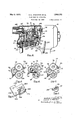
- Fig. 1 shows a mixing machine adapted for stirring, beatii mixin or yotherwise handlingvfoodstu s,- doug or other material, the machine shown bein 'of the ⁇ type es ially adapted to be use in the hoiisehoic- As shown,"the machine comprises an upright standard 10 supported 'yv the base 11 and in turn supportin an electric motor 12, a gear-changing an speed-reducing housing 13 and amixin'g lbowl lock washer;
- Fig. 1 7 is a schematic showing of the dif- ,ioo
- an electric control switch 19 is provided to control the starting and stop ⁇ ping of the motor 12. 4
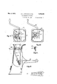
- the mixing bowl 14 is provided .with side brackets 20 which are seated upon the ends of supportingarms 21 provided on a bowl support 22 so that they extend along opposite sides of the bowl and assume the entire weight f the bowl and its contents.
- the bowl support 22 is preferablyl provided with a spring 23 whih is engaged by a smallnose 24 provided on the rearI ofthe bowl, to hold the bowl firmly on the support and prevent it from tilting during the operation offthe beater arm.
- the bowl support 22 is adapted ⁇ to move up and down along the standard 10 which is pro-v vided vwith a slide guide 25 for this purpose the opposite side edges of which guide the.
- arm 27 is'provided with an 'opening through which a link 30 extends, this link being pivhandle 32which is pivoted on the standard at 33.
- the link 30 as previously mentioned extends through an opening in the rigid arm 27, where the link and thear'm are operably connected togetherby means of a spring 34 which bears at one end against aiiut 35 provided on the bottom end of the link, theftop' of the spring pressing against a pressureplate ⁇ 36 on which rests a bent thrust v.member 37.
- This thrust memberV as shown in Fig. 7 is provided with Aa central hole l,38' through which the link '30 extends, and. the ridge 39 on'this bent thrust'inember en agesthe rigid arm 27 so that the weight of ti 4 0 p e bowl acting on this arm is transmitted through they spring to the link" 30'.k Cotter-pins 40 in the link 3,()v4 'are provided below the nut 35 and above the, arm 27 as shown.
- bowl-raising link 30 and lever 32 constitute in eiect a closed toggle the weight of the bowl or the bowl and its contents being transmitted through the arm 27 and link 30 tothe control lever in such a way as to tend 'to maintain the control lever in bowl-raised position as shown in this figure.
- constructionV is suchthat the howl' support is locked ⁇ firmly yet yieldingly against 4the stops-in its upper position n by the action of the spring 34 so that vibration and rattle of the bowl support'will not iio takeplace. The bowl being held firmly yet.
- the bowl-raising mechanism also has provisions for holding the bowl in a partly raised tween the support or 'mid-position; 'As shown in Figs. 18, 19V and 20 the control handle shaft 33 has mountedili fixed' position thereon, a block 41.10- cated between the bearingsin the sides of the standard and shorterY in extent than thel distance across these bearings to permitsome endwise movement of the shaft 33.
- the shaft 33 ⁇ -and the control handle are normally in Fig. 20 by a sprin 43 bearing against the hollow end of the sha t and against the stand- ⁇ ard side, and in this position the'block 41 rotates with theshaft without any effect on the mechanism.
- the motor 12 has a motor shaft 45 on the end of which is a pinion 46.
- This inion is adapted to cause the rotation of a riven shaft 47 in the u per portion of the gear casing 13 at high, ow o'r intermediate speeds dependent upon the character of material being treated by the arm 15 in the bowl.
- the shaft 47 is journaled at its ends in bearings 48 and 49 provided in the gear housing 13.
- Adjacent the bearing 48 the driven shaft carries a bevel gear 51 which meshes with gear 52 carried on a vertical shaft 53 which is below the shaft 47 and in the same vertical plane.
- the shaft 53 is rotatably mounted in the long fixed bearing 54 and the lower end of the shaft is inned to a rotatable assembly 55.
- the shag 16 is ro; tatably mounted in the assembly or planetary head 55 at a pointv spaced from the axis of the shaft 53, and is provided with a driving pinion 56 which meshes with an internal gear 57 carried by the housing.
- the shaft 16 is thus rotated about its own axis while it is bef in moved about the axis of the shaft 53 to e ciently mix andstir the material in the bowl.
- Shaft 47 as shown, is journaled in the end of casing 13 adjacent the top of the casing and the end of this shaft is suitably socketed to provide a coupling orclutch member cooperating with the internally tapered coupling hub around it to provideV an attachf ment drive for auxiliary apparatus.
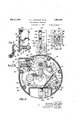
- the motor' pinion 46 engages constantly with Ithe gear 6 0 rotatable on va counter-shaft 61 mounted aty one sideof the motor shaft in the housing and ⁇ which also carries a pinion gear 62 fixed to gear 60' and-engaging gear 63 on a short shaft 64.
- the gear 62 is not shown in Fig. 2 as it lies behind the gear 63 but the construction will be apparent from Figs.' ⁇ 11 and 15.
- the vshaft 64 on the free end of whiclrthergear 63,is rotatably 'ournaled is fixed at one end in a stationary leari-ng 65 by means of a retaining screw or stud 67.
- This shaft' 64 also carries a pinion 68 journaled on the end of the shaft adjacent the gear 63.
- These gears63and 68 are adapted to be selectively engaged by lgears and 71 which are rigidly interconnected for simulta'ueous rotation and which are rotatably mounted on a shaft 72 supported in 'an adjustablek frame or yoke- 73.
- This frame or yoke is rotatably adjustable about the axis of the shaft 47 v, which isparallel to and spaced from the shaft 72.
- the frame is also ada ted to be shifted longitudinally of the sha 47 from its intermediate position as shown in F ig. 2.
- the frame carries a driven gear 76 which is keyed to a sleeve 75 which in turn is keyed to but axially shiftable on the shaft 47, gear 76 being constantly in meshi with the small gear 70 carried by the frame.
- the adjustablev frame 73 is in the position shown in Fig. 2 the motor pinion 46 drives the connected gears-.63 and 68 through the speed-reducing train of gears 60, 62 and '63. Gear 63 at this time engages gear ⁇ 71- and. thus through the small gear 70 causes a rotation ofthe gear 76 and the shaft'47.
- frame 73 may be moved to the left and simultaneously move about the axis of the shaft47' in a direction separating 'the gears to disengage the gears 63 and 71. After the frame 73 has been moved laterally a distance slight- ,ly exceeding the width of the gear 71 it may then be rocked about the axis of the shaft'47 to cause the small gear 70 to engage the large' gear 63, thus providing for high-speed opera- 1 tion of the shaft 47.
- the varrangement of the' power transmission" in the gear casing is particularly advantageous since it is quite' com act and permits the various gears and sha ts to be contained and lubricated in a small v,housing which is substantially coextensive in height and width the motor housing,
- the power is taken off laterally from the motor pinion 46 through and the power .is then transferred from a comparatively Alow point of the casing, through the tumbler or speed-varying gears, to a driven shaft 47 which extends towards I chine parallel'with and above the motor axis and which is provided at an upper part of the gear casing.
- The, 'tumbler or shifting gears 7 0 and 71 carried by the shifting frame are provided on the opposite side of the vertical Ivcenter of the gear casing, away from the speed-reducing gears 60 and 62 to utilize substantially all of the available space in the gear casingin a compact manner.
- the driven shaft 47 is journaled at its end in the outer side/ot the earl casing to provide a power take-ff at t is 'convenient point of the apparatus adapted to be clutched or connected to any suitable auxiliary appara-tus toK be driven suchA as a meat chopper or coffee grinder or the like, .which may be 'used in conjunctionwith the mixing machinef Below the driven shaft 47 and in the same-plane therewith the short vertical shaft 43 which drives the beater arm is so larranged that a sufficiently long bearing is provided totake care of the forces involved, the arrangement also beingfsuch that this shaft ⁇ 53 is provided compactly within the gear box.where it may the front of the mai' 71 and y63, this motion of the pin 80 being be well lubricated.
- This mixing machine construction is described land claimed in the divisional application, Serial No. 514,'150,
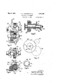
- the control member 18 has a single freedom of motion, the construction shown providing for rotational movements of the lever about the axisof a shaft 81 with which it is rigidly connected,
- a rotatable cam plate 85 ⁇ is fixed against rotation on the shaft p 81 by means of a pin 86, which engagesa pin slot 87vonthe hubportion of this plate,
- the fixed cam plate 83 is provided with a cam slot 89 having vertical portions 90 and 91 shaped to receive the operating pin 80 on the gear frame 73, and 'having cam surfaces 92 and 93 along which the operating pin 80 rides from the central position shown in Fig. -10 (corresponding to the intermediate speed-gear arrangement).
- spring 69 may bringing the gears into engagement by lowering the frame, is to vbe used in prevent rapid ⁇ downward movements of the frame. Uponv the completion. of the vrotary especially where thick oil the gear box which might' surface 95 or 96, moving l,
- the cam plate 83 cooperates with the cam vpin 80 of the gear-shifting frame to lower the gears 70 or 71 as the case may beinto the proximity of the gears 63 and 68 and permit full meshing engagement of the selected gear.
- the peripheral tooth surfaces of the two gears about to mesh come into contact thus temporarily preventing full meshing engagement, as soon as the motor starts and gears 68 and 63 make evenfa very small rotational movement the proper meshing occurs.
- the construction of the yokeor frame 73 and, the manner inwhich the yoke and the gear ,7 Gare supported and assembled is shown in Fi s. 12 to 14.
- the yoke 73 is freely rotatabe on the drive sleeve ⁇ 7 5 which is keyed tobut axiallymovable along shaft 47.
- the gear 76 is keyed to kthe drive Y sleeve 75 by a short key 77 having a length corresponding tothe gear width.
- On the inner side of the gear 76 is a key-retaining washer 78 having a notch 7 9.and a lock ear f 180. With the lock ear extending to the rear v the notch 79 will beat the open side of the yoke hub, and as the gears 70 and 71 areV vnot in proper position.
- the key 77 N may be inserte into the short key slot 1n the sleeve and the sleeve and key together moved axially into gear 76 and along vthe frame 73 into its Ax1al movement 'of the'A 70 sleeve and key in relation to the washer 78 during assembly is permitted by the notch 79 but after the sleeve is inrposition it is retained against. endwise movement in relation to the frame 73 by the key which is definitely fixed 75 in relation to the sleeve by the length of the -keyslot,'this key abutting against the frame 73 on the one hand and against the washer.
- ⁇ key 77 isl retained within the gear 76 and 85- this also prevents shifting movements of the yoke along the sleeve 75.
- the gears 70 and 71 may now be added by inserting the shaft 72 endwise into the yoke. and throughV these gears, the shaft 72 being then retained 90A against endwise movement by a suitable cotter-pin.
- the small pinion 46 on the motor shaft 45 of course rotates at a comparativelyl high speed and drives a much larger gear 60 which 95 is preferably provided with a tooth-providing rim portion of'fiber to reduce noise during f operation.
- Gear 60 islixed to smaller gear 62 l p s which drives the speedreducing gear 63.A
- Theshaft 64 on which the gear 63 is rotatably 100 supported lies somewhat below the level of the f shaft 61, see Figs. I11, 15 and A17, while the m0- tor shaft 45 lies somewhat above that leveL Shaft 61 is eccentrically mounted at its ends the eccentricity being amatter of only a few thousandths of an inch/and being shown somewhat exaggerated inFig. l5 so that it will be i i apparent.
- the eccentric adjustment is permitted when the lock nut 185 threaded on the end of the shaft 61 and the set screw 186 are loosened, the end of the shaft 61 being slotted lso that it may be rotatably adjusted, and then held in adjusted position by theset screw and the lock nut.
- the gears 60 and 46 may be adjusted as to ncenters so that they run noiselessly and the gears 62 and 63 may also be regulated for the proper backlash for noiseless operation.
- Fig. 17 the eccentric adjustment and gear-center regulation is shown but to a greatly exaggerated degree. As a matter of fact the eccentric adjustment amounts to only a few thousandths of an inch but the points a and c designating 2 ins 61, are graphically shown considerably spaced from the center of the eccentric bearing support.
- the pitch circles of gears 46 and 63 are indicated at 46 and 63 (the displacement /f these circlesabove andbelow the level of 130V the point being'g-reatly exaggerated for illustration) It will be noted t at as the axes cf the gears 46 and 63 lie in dierent planes containing the axis of the shaft 61, the ad.u justment of the center distances to the gear L16 and to the gear 63 is effected in a diierential manner, the arrangement being such that the axis of shaft 61 can be moved toward both the driven and the driving gear, and also providing for movements of the/axis of the shaft 61 toward one of these gears and away from the other. vIn the articular construction illustrated in Fig.
- the position of the axis of the shaft 61 may be adjusted about the center :v so as to increase or decrease the spacing of the axis, or to move these axes in a differential manner and throughout diierent distances.
- the axis 61 may be moved from the point c up to the point a approximately on the o posite side of t e center it being a parent j t at the ad'ustment of the axis of shail; 61 increases slig tly the distance to the axis of gear 63 and decreases the distance to the axis of ar 46.
- the motor ⁇ is started of the motor-control switch 19 ⁇ having a switch handle 101, the latter being shown in and stopped by means motor-energizing position in Fig. 8.
- This switch means 101 may be moved horizontally tov an od position. shown in Fig. 1 to stop the rotation of the motor.
- the motor-control switch is mounted by suitable bolts on the mounting plate 82 along side the control handle 18, and an interlock is ⁇ providedvbetween the motor switch and the speed-changving lever 18 to prevent operation of the mo-l tor-control switch to on position unless the control lever '18 Vis in one of the three positions corresponding to positions of the movable gear frame where the ge'ar 70 or the gear 71 is in proper mesh with the gear 63 or the gear 68.
- the switch means 101 extends through lan opening 102 in an interlock Aplate 103 which is slotted at 104 and 105 to receive the 'bushings 106 mounted on the supporting plate 82, and which thus guide the interlock plate 103 for reciprocatory movement toward' and away from he shaft 81.
- the shaft 81 carries a notched plate 107 which is suitably :grooved as shown 'at 108 to receive a pin 109 ex-l tending through the shaft so that the notched plate 107 rotates with the shaft.
- the interlock is also arplate 85 also presses against the hub portion l of 7the notched plate as shown to ⁇ maintain it 107 .is provided with three notches 110, 111 and 112 ada ted to receive a rounded tongue 113 provide on the end of the interlock plate 103. be engaged by the tongue 113 of the inter-A lock plate when the lever 18 extends upwardly andthe pointer'94 is adjacent position 3corresponding to high-speed operation, and the notcheslll and 112 will -be' in position to be engaged by the tongue 113 at intermediate and low-speed settings respectively.
- the control handle 18 is in one of the three operating positions and the gears are properly meshed or inpposition about.
- the switch 101 can be moved to motor-energizing or on position since the tongue '113 will notl then be re strained by t e cylindrical surface 114 of the notched plate, but in any other position of the control handle 18 this cylindrical surface 114 will prevent the motor-starting switch from being operated, and tle operation of the motor therefore cannot be effected unless the gear train is properly meshed or. .about ready for meshing engageagainst the mounting plate 82.
- the plate' The notch will be in position to ment, It will also be apparentthat when the tongue 113 is in engagement withone of operator to know ⁇ when the control lever 18 is in fthe exact position to permit tongue 113 o the interlock plate to be received in one of the notches 110, 111, 112 the mounting plate 82 is preferably bulged inwardly as indicated at 115 in Figs. 9 and 11, the bulge being so shaped and positioned as to be received in the notch 112 when the control lever 18 is in intermediate-speed position,
- the driven gear 71, or the gear 7.0 of the shifting frame, as thecase may be, will drop into full meshing engagement, due to the weight of the frame and the action of the spring 69.
- the motor interlock being such that the motorcan be started even when the gears are Vnot fully' in mesh provides an arrangement which is particularly desirable, in that it permits the starting of the apparatus* under any conditions as long as the gears are ready to mesh properly when the motor' starts.
- Suitable means are provided for maintaining a proper spacing of the shaftr72 from the shaft 64 when the .gears "X0 or 71 are engaged with the gears 68 or 63 to provide for suitable operating backlash of the gears.
- a sto plate 120 is mounted on the houslng 13 inside the latter in position to vbe engaged by a tongue 121extending from 'the lower end of the frame 73.
- the stop plate' 120 has surfaces 122, 123 and 124V suitably olset and spaced a art so that the tongue 121 may engage Wit Ythese surfaces at lowspeed', intermediate-speed, and high-speed adjustments respectively.
- the stop plate 120 is provided with a depending side 125 which is slotted at 12.6 to receive a. fastening screw "l27'threaded into a wall of the housing 13, so
- the stop plate is-provided with an end portion 128 which is guided in a slot 129 provided in a part 130 of the housing 13.
- the end 131 of this part of the stop plate engages a conical end 132 of van adjusting screw 133, which is threaded in the boss 134 of the lower wall of the housing 13 so that the 'adjusting member 133fis accessible from the bottom of this housing.
- a clock screw 187 preferably is threaded into the boss 134, to jam against the bottom of the adjusting screw 133 to hold the latter in adjusted position.
- the adjusting member f133 may be'rotated4 after the temporary removal of the lock screw 187 ⁇ to bring the stop plate to a suitable position to properly regulate the ybacklash of the gears.
- the-,backlash of the gears issi- ⁇ multaneously adjusted for the threeoperating positionsof the gears and theadjustments in the backlash may be easily effected from the exterior ofy the housin and during operation.
- a driving member forf shifting said' tumbler gear, and an operative interconection betweensaid control member and said tumbler gear including a lost motion connection to permit said tumbler gear toremain out of meshing engagement with a mating gear 4when-said control member is in an operative gear meshing position.
- a tumbler gear rotatable about its axis and also shiftable endwise along its axis to engage mating gears
- a control member for shifting said tumbler gear
- an operative interconnection between said control member and said tumbler gear including a lost motion connection to permit said tumbler gear to remainout of meshing engagement with a mating gear when said control member is in an operative gear meshing position, and means" ⁇ f0r definitely locating said control member in its gear meshing positions.
- a driving member, a driven meinber, a change-speed gearing between said members including a tumbler gear rotatable about its axis and also shiftable endwise along its axis to engage mating gears, a control member for shifting said tumbler gear, an operative interconnection between said control memberand said tumbler gear including a lost motion connection to permit said tumbler gear to remain out of meshing engagement with a mating gear when said control member is in an operative gear meshing posi- Y which is permanently in mesh with said mentioned gear, a key for holding said rotatable gear to said sleeve, means rotatable aboutY the sleeve axis for retaining said key in said rotatable gear, said last means serving to fix said frame against axial movement on said sleeve, and means for moving said frame for engaging one of said members with one or the other of said pair of gears.
- a driving gear a driven gear, a pair of connected axially aligned gears one engaging said driving gear and one engaging said driven gear, and a sensitive eccentric adjustment for said pair of gears to var the gear-center distances to adjust the bac lash of said intermeshing gears.
- a driving gear In a food-handling machine of the class described, a driving gear, a driven gear, a pair of connected axially laligned gears, one engaging said driving gear and one engaging said driven gear, and sensitive adjusting means for shifting said pair of gears to vary gear-center distances to adjust the backlash of said intermeshing gears, the drivin and driven gear axes being spaced apart and lying in dve'rent planes containing the axis of said aligned gears.
- the gearand comprising an adjustable gear, a plurality of mating. gears, means supporting said adjustable gear to( move about a fixed axis displaced from the axis of the gear and to move in the direction of the xed axis to select different mating gears, said adjustable gear being adapted to move into engagement with a selected mating gear automatically upon relative rotation of said adjustable gear and the respectivemating gear,
- apparatus of the 'character described having an electroc motor, a motor interconnected with, sa'id motor, a driven member, change-speed gearing operatively interconnectlng sa1d ⁇ dr1v1ng and drlven members and comprising an adjustable gear, a plurality of mating gears, means supporting said adjustable gear to move about a fixed axis displaced from the axis of the gear and to move in the .direction-pf ⁇ the fixed axis to select different mating gears, a rotatable control member operatively.
- said interlock associated with said interlock and having a plurality'of deflnite gear meshing positions, and an operative interconnection between said rotatable control member .and said adjustable gear for transforming rotary movement osaid rotatable control member into rotational and shifting movements of said adjustable gear, said operative interconnection including -a lost motion portion constructed to provide movement of said rotatable control member fully into an operative gear meshing position when saidl adjustable gear remains out of meshing engagement with a respective mating' gear.
- a driving member operatively interconnected with said motor, a driven' member, change-speed gearing operatively interconnecting said driving and driven y 4ov members comprising a tumbler gear, a plurality of mating gears, means Vsu porting said tumbler gear to move about a xed axis displaced from the axis of the gear and to move in the direction of the ixed axis to vselect different mating gears, a rotatable control member operatively associated with said interlock and having aplurality of denite gear meshing positions, and an operative interconnection between said rotatable control member' and said tumbler gear-for transforming rotary movement of said rotatable control member into rotational and Vshifting movements of said tumbler gear, said operative interconnection including a yielding portion adapted to provide for'movement of said .rotatable control member fully
- a change-speed gearing between said members comprising an'adjustable gear, mating gears adapted to be selectively.
- the .adjustable gear means supporting said adjustable gear. for movement aboutan axis to engage or disengage a mating gear and toshift bodily to select a'dierent mating gear, a control member, a movable cam member operated thereby, a stationary cam 'member cooerating withI the movable means engaging both of said cam members for'operating said gearsupportingmeans so that movements ofthe movablegcam plate are ei'ective in moving the gear-supporting 'means to disengage the adjustable'gear from one mating gear and engage it 'with another mating gear.
- a driving. member a driven member a change-speed gearing between sa1d mem ers comprising an adjustable v gear, mating gears adapted to be selectively engaged by the adjustable gear, means sup- I porting-said adjustable gear for movement about an axis to engage or disengage a mating gear and to shift bodily to select a dii'erent mating gear, a rotatable control member, a cam plate rotatably mounted and moved by said rotatable member, a stationary cam plate cooperating therewith, and a device on said gear-supporting means engaging said cam plates so. that rotational movement of the Arotatable cam plate imparts a combined shifting and rotational moveinent of the gear-supporting member for the lpu ose. desired.
- a gear casing a drive shaft having an end thereof extending only into 011e end of said gear casing and having a drive gear thereon within said gear casing, spaced par-- allelly extending shafts mounted within said ⁇ gear casing, ys eed reducing intermeshing gearing'on sai parallell'yT extending shafts and in driven relationshi with said drive gear, a tumbler gear sha t mounted within said ear casing arallel to said mentioned 'paral elly extending shafts, and a tumbler gearing ro'ckably and axially movable on said tumbler gear shaft be ond the extending end vof said drive shaft or interconnecting the v said 4arallelly extending shafts with said tumb er gear shaft in different ⁇ speed relationships.
- a gear casing a drive shaft having an end n thereof extendin only. into one end :of said gear casing at su sta-ntially the longitudinal axis thereof, a drive gear on said drive shaft within said ear casing, spaced parallelly extending shafts mounted generally on one side of said gear casing with respect to a transverse plane passing through thesaid longii Atudinal axisthereofone of said parallelly extending shafts havinga gear in intermeshing relationship with said drive gear, speed reducing intermeshing gearing interconnecting said spaced parallelly extending shafts, additional gearing on the other of said parallelly extending shafts, a tumbler gear shaft mounted generallyI on the other side of said gear casing'with respect to said mentioned transverse plane and arranged. parallel to saidl mentioned parallelly extending shafts, a
- a gear casing In apparatus of the character de scribed, a gear casing, a drive shaft extend ling within said gear casing, spaced parallelly extending shafts mounted within said gear casing, speed reducing intermeshing gearing on said parallellyextending shafts, a driving connection between saiddrive shaft and one of saidpara'llelly extending'shafts, a third' parallelly extending shaft mounted within said gear casing, means including speed change gearing interconnecting said third shaft in driven relationship with the other of said parallelly extending shafts, a driven said third shaft and positioned within said vshaft extending generally at right angles to gear casing beyond said speed reducing.inter.
- a gear casing generally circular in cross section having a substantially horizontal longitudinal axis, a horizontaldrive shaft having an end thereof extending only into one end of said gear casing substantiall 1n line -with the longitudinal axis thereo spaced parallelly extending horizontal shafts mounted Within said gear casing iat-one side of the longitudinal axis thereof, speed reducing intermeshing gearing on said parallelly extending shafts, va'driving connection betweemsaid drive shaft and one of said parallelly extending'shafts, a third parallelly extending horizontal shaft mounted within said gear casing at one side of the longitudinal axis thereof and substantially in vertical alignment with said longitudinal axis, means including speed change gearing positioned beyond the said extending end of said drive shaft interconnecting said third shaft in driven relationship with the other pf said Vparallellyextending shafts, a vertical driven shaft mounted within said gear casing beyond said speed reducing intermeshing gearing and "said speed change gearing, and a driving connection between said third shaft
- a gear casing 'generally circular inV cross section having aL substantially horizontal longitudinal axis, a horizontal drive shaft having an end thereof extending only 'ilto one end of said gear casing substantially in line with the longitudinal axis thereof, spaced parallelly extending horizontal shafts mounted within said gear casing'at one side mountedwithin said gear casing beyond said speed reducing intermeshing gearing and said speed change'gearing, a driving connection between said third shaft and said vertical driven shaft,and a -horizontal power takeomounted in said .,gear casing in alignment with said third parallelly Aeidzending hori-
Landscapes
- Life Sciences & Earth Sciences (AREA)
- Engineering & Computer Science (AREA)
- Food Science & Technology (AREA)
- Chemical & Material Sciences (AREA)
- Chemical Kinetics & Catalysis (AREA)
- Gear Transmission (AREA)
Description
May 9, 1933. H, 1 JOHNSTON ET AL 1,908,153'
FOOD HANDLING APPARATUS 5 Sheets-Sheef 1 'Filed May 14,4928 A II-lllll [NVE/VIDA vnd/Md A TTRNEY May 9, 1933- I H. L. JOHNSTON ETAL f l 1,908,153
F001) HANDLING APPARATUS Filed May 14,1928 5 sheets-sheet 2 Mil rlllllllll ll//l :ff Hw,
Mhse/ ATTORLVEY May 9, 1933.
H'. L. JOHNSTON ET AL FOOD HANDLING APPARATUS Filed May 14, 1928 l 5 sheets-sheetv s v AATTORNEY May 9.*1933.
H. L. JOHNSTON Er AL Fbon HANDLING APPARATUS Filed May 14,'*1928l 5 Sheets-Sheetv 4 May 9. l933- H. L. JOHNSTON |=:r AL
FOOD HANDLING APPARATUS 5 Sheets-Sheet 5 Filed may 14, 1928 ATTORNEY j Plienied May s, 1933 UNiTED STATE-snEanEaT n IoiiNsToN Nn navin A. MEExEn. or Tnoy, omo, sssIeNoas, nr NEsNE sin mmol-creams comm, or Taor, omo.
7 AssIGNmENTs, To THE KITCHEN A conroaaTIoN or omo *PATENT ori-icaroon HANDLING iiiiiaisuiTUs A Application Med lay 14,
" Thisinvention relates to apparatusfor fhandling or mixing foodstuffs or other 'mabodying an adjustable or movable gear which is adapted to be bodily rotated about an axis and also shifted endwise in changing-speed ratios, and havinga ear-changing member which has but one` reedom of motion to effect the operation of the adjustable gear.
Another object is the provision of gearing adapted for use in a mixing machine embodying an adjustment for differentially varying backlash of a plurality of gear en- 12, i
lFig. 15 is a section thru thecounter-sliaft gaglments.
' other object of the invention is to provide a change-speed gearing of the character mentioned, having sim anism for varying they acklash for the adjustable gear and a gear engaged thereby.
A further object is the provision of a motor-driven mixing machine ofthe'character mentioned incorporating Ia change-speed Gearing, whichhas a controlswitch interlocked with the speed-changin Still 'another object of the invention is the provision in a mixing or food-treating machine having a bowl which may be raised or lowered, of a simple mechanism for raising and maintaining the bowl in its raised posithe foodle adjusting mechdeviceto 'a prevent improper' operation of 't e machine.
'1928. Serial No. 277,616.
Figs. 3, 4 and 5 are representations of the various positions of the adjustablev s chan e ar for Ihigh-speed, intermediatespec an slow-speed operation of the mixing arm or member respectively;
Fig. 6 isa detail view of the backlash stop; Fig. 7 is a detail of a part of the bowlraising mechanism; j
Fig.' 8 is a horizontal 'section through the control switch and interlock on the line 8--8 of Fig. 9; 1
Fi 9.is a rear elevation of the control switc and interlock;
Fig. 10 is a detail of the stationaryfand the rotatable cam plates 1 Fig. 11 is a vertical sectionV on the line 11-11 of Fig. 1; 'A
, Fig. 12 is a detail oflthe shifting frame and j gear arrangement;
12F`g. 13 is asection line 13-13 of Fig. 14 is a section on line 14-14 of Fig.
'gears onA line 15-15 of Fig. 11;
Fig. 16 is a detail view of the -ferential gear-spacing ad'ustment; i
Fig. 18 is a side elevation of the pedestal with the bow-l support in a mid-position, part Fig. 20 is a top plan view of the pedestal wih the handle m`free or released position; an
Fig. 21 is a vertical section through the mid-position stop of the bowl support on the line 21,-21 of Fig. 19.
Referring more particularly to the vdrawlings Fig. 1 shows a mixing machine adapted for stirring, beatii mixin or yotherwise handlingvfoodstu s,- doug or other material, the machine shown bein 'of the` type es ially adapted to be use in the hoiisehoic- As shown,"the machine comprises an upright standard 10 supported 'yv the base 11 and in turn supportin an electric motor 12, a gear-changing an speed-reducing housing 13 and amixin'g lbowl lock washer; Fig. 1 7 is a schematic showing of the dif- ,ioo
to be manually operated to select the proper speed foi-suitable operation vof the beater arm 15,an'd an electric control switch 19 is provided to control the starting and stop` ping of the motor 12. 4
To effect the raising and lowering of the mixing bowl a simplemechanism is provided lwhich may be easily. operated and which maintains the bowl in a raisedposition with- Out requiring the operation of locking pawls or similar operable locking` devices) The mixing bowl 14 isprovided .with side brackets 20 which are seated upon the ends of supportingarms 21 provided on a bowl support 22 so that they extend along opposite sides of the bowl and assume the entire weight f the bowl and its contents. yThe bowl support 22 is preferablyl provided with a spring 23 whih is engaged by a smallnose 24 provided on the rearI ofthe bowl, to hold the bowl firmly on the support and prevent it from tilting during the operation offthe beater arm. i
The bowl support 22 is adapted` to move up and down along the standard 10 which is pro-v vided vwith a slide guide 25 for this purpose the opposite side edges of which guide the.
movements of the support 22. When thebowl is in 'its raised position the top of the bowl support 22 engages a pair ,of laterally spaced/ stop lugs 26 provided 'in the standard so that the upper limit of movement ozt' the bowl is thus definitely determined. f Rigid with" the bowl support22 is an arm'27 which exl tends rearwardly through a verticalislot 28 ota'lly4 connected at 31 toa 'control or lift in the forward wall 290i the standard. ,This
This thrust memberV as shown in Fig. 7 is provided with Aa central hole l,38' through which the link '30 extends, and. the ridge 39 on'this bent thrust'inember en agesthe rigid arm 27 so that the weight of ti 4 0 p e bowl acting on this arm is transmitted through they spring to the link" 30'.k Cotter-pins 40 in the link 3,()v4 'are provided below the nut 35 and above the, arm 27 as shown. When ,the lever 32is inthe lpressed outwardly to the position'indicated position showniin Fig. ithe bowl-raising link 30 and lever 32 constitute in eiect a closed toggle the weight of the bowl or the bowl and its contents being transmitted through the arm 27 and link 30 tothe control lever in such a way as to tend 'to maintain the control lever in bowl-raised position as shown in this figure.
This is due/to the fact that the axis 33 of the control lever. is somewhat out of alignment with Lthe points of connection of the link 30 and with the control lever and with the arm 27, the axis 33 as shown in Fig. 1 being slightly to the left of the line through these points,
and the link 30 being bent at the point l1 2/oi' this purpose. When the lever is in b'owlraisedposition, as shown, the lsprin 34 is' compressed between the nut 35 and t e arm 27, the upper limit of movement ofthe arm 27 being limited by the stops 26 which areso positioned Ythat the-spring 34 will be compressed when the bowl is in its uppermost position and in cooperative'association with the beater arm 15. When the controlv handle 32.
is rotated in a counter-clockwise direction asV shown by the dotted arrow in Fig. 1 the initial movement will cause a further compression of the "spring 34 since the arni 27 cannot move upwardly from the position/ shown.
Then after the points 31, 33 and 39 arealigned, further lowering movement of the controlhandle will permit the bowl support v adjusted or moved into its elevated position 1n i cooperative relation` wi-tli the beater arm.
Furthermore the constructionV is suchthat the howl' support is locked `firmly yet yieldingly against 4the stops-in its upper position n by the action of the spring 34 so that vibration and rattle of the bowl support'will not iio takeplace. The bowl being held firmly yet.,
yielding] -on the bowl support, permits no noise an rattle to occur between those parts4 and 'the bowl support ust described eliminates' noise and rattle and the standard, the result being a per ectly quiet arrxangement yet one which permits variations 1nl the bowl height and its quick removal fronrlthe machine.
The bowl-raising mechanism also has provisions for holding the bowl in a partly raised tween the support or 'mid-position; 'As shown in Figs. 18, 19V and 20 the control handle shaft 33 has mountedili fixed' position thereon, a block 41.10- cated between the bearingsin the sides of the standard and shorterY in extent than thel distance across these bearings to permitsome endwise movement of the shaft 33. The shaft 33`-and the control handle are normally in Fig. 20 by a sprin 43 bearing against the hollow end of the sha t and against the stand-` ard side, and in this position the'block 41 rotates with theshaft without any effect on the mechanism. However when the handle is pressed in towards the standard after the bowl has been partly raised, a tongue 44 on the block 41 is brought over a socket stop 44 and if the handle is then lowered some little distance'the tongue will be retained 1n lthe socket stop and the bowl held partly spring 43 moves the handle and its shaft outwardly. VThe bowl is therefore veryeasily adjusted and is held either in raised or lowered position, .or in a mid-position, by the proper operation of the single control handle. This bowl raising mechanism is described and claimed in the divisional a plicat-ion, Serial No. 330,837, filed January 1929,
.now Patent No. 1,767,002, dated June 24,
Referring more particularly to Figs. 2 to 5 and-toFig. 11, the motor 12 has a motor shaft 45 on the end of which is a pinion 46. This inion is adapted to cause the rotation of a riven shaft 47 in the u per portion of the gear casing 13 at high, ow o'r intermediate speeds dependent upon the character of material being treated by the arm 15 in the bowl. The shaft 47 is journaled at its ends in bearings 48 and 49 provided in the gear housing 13. Adjacent the bearing 48 the driven shaft carries a bevel gear 51 which meshes with gear 52 carried on a vertical shaft 53 which is below the shaft 47 and in the same vertical plane. The shaft 53 is rotatably mounted in the long fixed bearing 54 and the lower end of the shaft is inned to a rotatable assembly 55. The shag 16 is ro; tatably mounted in the assembly or planetary head 55 at a pointv spaced from the axis of the shaft 53, and is provided with a driving pinion 56 which meshes with an internal gear 57 carried by the housing. The shaft 16 is thus rotated about its own axis while it is bef in moved about the axis of the shaft 53 to e ciently mix andstir the material in the bowl. Shaft 47 as shown, is journaled in the end of casing 13 adjacent the top of the casing and the end of this shaft is suitably socketed to provide a coupling orclutch member cooperating with the internally tapered coupling hub around it to provideV an attachf ment drive for auxiliary apparatus.
The motor' pinion 46 engages constantly with Ithe gear 6 0 rotatable on va counter-shaft 61 mounted aty one sideof the motor shaft in the housing and `whichalso carries a pinion gear 62 fixed to gear 60' and-engaging gear 63 on a short shaft 64. The gear 62 is not shown in Fig. 2 as it lies behind the gear 63 but the construction will be apparent from Figs.'` 11 and 15. The vshaft 64 on the free end of whiclrthergear 63,is rotatably 'ournaled is fixed at one end in a stationary leari-ng 65 by means of a retaining screw or stud 67. This shaft' 64 also carries a pinion 68 journaled on the end of the shaft adjacent the gear 63. These gears63and 68 are adapted to be selectively engaged by lgears and 71 which are rigidly interconnected for simulta'ueous rotation and which are rotatably mounted on a shaft 72 supported in 'an adjustablek frame or yoke- 73. This frame or yoke is rotatably adjustable about the axis of the shaft 47 v, which isparallel to and spaced from the shaft 72. The frame is also ada ted to be shifted longitudinally of the sha 47 from its intermediate position as shown in F ig. 2. The frame carries a driven gear 76 which is keyed to a sleeve 75 which in turn is keyed to but axially shiftable on the shaft 47, gear 76 being constantly in meshi with the small gear 70 carried by the frame.
lfVhen the adjustablev frame 73 is in the position shown in Fig. 2 the motor pinion 46 drives the connected gears-.63 and 68 through the speed-reducing train of gears 60, 62 and '63. Gear 63 at this time engages gear `71- and. thus through the small gear 70 causes a rotation ofthe gear 76 and the shaft'47. The
when so moved to the right and then rocked about the axis of the shaft 47 the pinion 68 will be engaged by the large gear 71 carried by the frame and the shaft 47 will thus-be driven at a comparatively slow speed Infrom the motor. When the lgear-supporting frame is moved from the slow-speed position it is first necessary to move it about thel axis of the shaft 47 until the two large gears 63 and 71 are relatively displaced far enough to permit the lateral movements of the frame 73 without causing these two gears to clash. i The 4low-speed larrangement of' the gearing is shown in Fig. 5. By reason of a gearingconstruction as Just -describedit is possible to enclose the gears in a box or housing of minimum size supplied with suitable lubricant for the operatingparts, while still obtaining sufficient reduction speed at the beater arm I attaching bolts which pass through the at- -taching holes v188 apparent in Fig. 11. lelectric motoris mounted directly above and kwith the dimensions of The on the top ofthe pedestal or standard, with its axis. of rotation extending horizontally toward the front of the .machine so that the power may be directly `supplied to the gearchanging and speed-reducing mechanism. The varrangement of the' power transmission" in the gear casing is particularly advantageous since it is quite' com act and permits the various gears and sha ts to be contained and lubricated in a small v,housing which is substantially coextensive in height and width the motor housing,
sand which is preferably `formed asa conspeed-reducing mechanism,
ltol
tinuation of the end of the motor housing. lt
'will be noted that the power is taken off laterally from the motor pinion 46 through and the power .is then transferred from a comparatively Alow point of the casing, through the tumbler or speed-varying gears, to a driven shaft 47 which extends towards I chine parallel'with and above the motor axis and which is provided at an upper part of the gear casing. The, 'tumbler or shifting gears 7 0 and 71 carried by the shifting frame are provided on the opposite side of the vertical Ivcenter of the gear casing, away from the speed-reducing gears 60 and 62 to utilize substantially all of the available space in the gear casingin a compact manner. The driven shaft 47 is journaled at its end in the outer side/ot the earl casing to provide a power take-ff at t is 'convenient point of the apparatus adapted to be clutched or connected to any suitable auxiliary appara-tus toK be driven suchA as a meat chopper or coffee grinder or the like, .which may be 'used in conjunctionwith the mixing machinef Below the driven shaft 47 and in the same-plane therewith the short vertical shaft 43 which drives the beater arm is so larranged that a sufficiently long bearing is provided totake care of the forces involved, the arrangement also beingfsuch that this shaft`53 is provided compactly within the gear box.where it may the front of the mai' 71 and y63, this motion of the pin 80 being be well lubricated. e This mixing machine construction is described land claimed in the divisional application, Serial No. 514,'150,
`filed February 7,1931.
T he gear-supporting frame 73 is moved bodily -and is rotated about the axis of the shaft 47 by Ameansl of a pin 80 which is operated fromthe rotatable control member 18 in the following manner: The control member 18 has a single freedom of motion, the construction shown providing for rotational movements of the lever about the axisof a shaft 81 with which it is rigidly connected,
and which is rotatably journaled' in the mounting plate 82 and in a fixed cam plate 83, which is mounted parallel tol the plate 82 by `means of the bolts 84. A rotatable cam plate 85` is fixed against rotation on the shaft p 81 by means of a pin 86, which engagesa pin slot 87vonthe hubportion of this plate,
and a spring '88 engages' this hub portion to normally maintain the two cam plates adjacent one another. The fixed cam plate 83 is provided with a cam slot 89 having vertical portions 90 and 91 shaped to receive the operating pin 80 on the gear frame 73, and 'having cam surfaces 92 and 93 along which the operating pin 80 rides from the central position shown in Fig. -10 (corresponding to the intermediate speed-gear arrangement). When the control handle 18 is so adjusted that the index point 94 is adjacent position 2, see Fig. 1 .the parts will be in the position indicated in Figs. 8` to 11 inclusive, corresponding to the intermediate-speed positioning. p A clockwise rotation of the control handle 18 froml this-position will cause the operating pin 80 to be moved along the cam surface 92 to lower the pin 80 and thus raise the frame and, at the y same time shift the gear frame 73 laterally to disengage the gears Ylower end of slot. 90 in the fixed cam plate.
be provided to assist in ,A .spring 69 may bringing the gears into engagement by lowering the frame, is to vbe used in prevent rapid` downward movements of the frame. Uponv the completion. of the vrotary especially where thick oil the gear box which might' surface 95 or 96, moving l,
movement of the control lever 18 in bringing the pointer 94 opposite position 3 the weight ofthe gears 70 and71 and of the frame 73 causes the pin' 80 to ris in the slot 90, this motion being-assisted, portion of the camv surface 96 of the movable c am plate. This motion of the pin is effecif need be, by the outer l tive in lowering the gear 70 into engagement with the gear 63 for high-speed operation of the beater arm, it being understood that the lateral motion of the pin 80 from its intermediate position to the cam slot 90 has shifted the movable gear assembly along the axis of the shaft 47. Clockwise rotation of the control lever 18 from this high-speed positioning causes the cam surface 95 of the movable cam plate to first lower the pin 80 and raises the gear 70 out of engagement with the gear 63, the weight of the gear assembly 4paratively slow speeds by the motor.
assisted by the action of spring 69 then causing the pin 80 to yrise as it is moved toward the intermediate position shown in Fig. 10. lt will be apparent that movement of the control lever 18 to a position, as shown in Fig. 1, corresponding to low-speed operation, moves the pin 80 downwardly and laterally and then upwardly in the cam slot 91 to bring the gears to the position shown in Fig. 5 where the shaft 47.1is rotated at ctiln- 1e gear ratio is thus changed in avery quick and easy manner by merely rotating the control handle to the desired position for the proper operating speed of the beater.
ln the construction of the mechanism by which the gear-shifting frame is moved the cam plate 83 cooperates with the cam vpin 80 of the gear-shifting frame to lower the gears 70 or 71 as the case may beinto the proximity of the gears 63 and 68 and permit full meshing engagement of the selected gear. In case the peripheral tooth surfaces of the two gears about to mesh come into contact thus temporarily preventing full meshing engagement, as soon as the motor starts and gears 68 and 63 make evenfa very small rotational movement the proper meshing occurs. The full meshing of engaging gears is completed automatically without further operation on the part of the attendant, the comparatively vsmall angular movement of the frame 73 to bring one of the gea-rs of the gear tumbler into full meshing engagement with the gear that drives it being without effect upon the control handle 18 due to the provision of sufficient lost .notion in the mechanical connection between these parts.
The construction of the yokeor frame 73 and, the manner inwhich the yoke and the gear ,7 Gare supported and assembled is shown in Fi s. 12 to 14. The yoke 73 is freely rotatabe on the drive sleeve`7 5 which is keyed tobut axiallymovable along shaft 47. Before the gears 70, 71 are assembled on the yoke'. 73. the gear 76 is keyed to kthe drive Y sleeve 75 by a short key 77 having a length corresponding tothe gear width. On the inner side of the gear 76 is a key-retaining washer 78 having a notch 7 9.and a lock ear f 180. With the lock ear extending to the rear v the notch 79 will beat the open side of the yoke hub, and as the gears 70 and 71 areV vnot in proper position.
vtwo different positions of the center of shaft lace, at this time, the key 77 Nmay be inserte into the short key slot 1n the sleeve and the sleeve and key together moved axially into gear 76 and along vthe frame 73 into its Ax1al movement 'of the'A 70 sleeve and key in relation to the washer 78 during assembly is permitted by the notch 79 but after the sleeve is inrposition it is retained against. endwise movement in relation to the frame 73 by the key which is definitely fixed 75 in relation to the sleeve by the length of the -keyslot,'this key abutting against the frame 73 on the one hand and against the washer.
78 which has been turned about 90'o to bring the notch 79 and the open side of the frame 80.- bearing out of registration. The washer 78.
is heldin the turnedkey retaining position by bending the lock ear down between two retaining lugs 181 y'on the yoke. Thus. the
`key 77 isl retained within the gear 76 and 85- this also prevents shifting movements of the yoke along the sleeve 75. The gears 70 and 71 may now be added by inserting the shaft 72 endwise into the yoke. and throughV these gears, the shaft 72 being then retained 90A against endwise movement by a suitable cotter-pin. i The small pinion 46 on the motor shaft 45 of course rotates at a comparativelyl high speed and drives a much larger gear 60 which 95 is preferably provided with a tooth-providing rim portion of'fiber to reduce noise during f operation. Gear 60 islixed to smaller gear 62 l p s which drives the speedreducing gear 63.A
The motor` is started of the motor-control switch 19` having a switch handle 101, the latter being shown in and stopped by means motor-energizing position in Fig. 8. This switch means 101 may be moved horizontally tov an od position. shown in Fig. 1 to stop the rotation of the motor. The motor-control switch is mounted by suitable bolts on the mounting plate 82 along side the control handle 18, and an interlock is `providedvbetween the motor switch and the speed-changving lever 18 to prevent operation of the mo-l tor-control switch to on position unless the control lever '18 Vis in one of the three positions corresponding to positions of the movable gear frame where the ge'ar 70 or the gear 71 is in proper mesh with the gear 63 or the gear 68. ranged to prevent the control lever 18 from being operated when the motor is 'running so that the gear train will not be thrown out of mesh when power is applied to the beater arm. As shown in Figs. 8 and 9 the switch means 101 extends through lan opening 102 in an interlock Aplate 103 which is slotted at 104 and 105 to receive the 'bushings 106 mounted on the supporting plate 82, and which thus guide the interlock plate 103 for reciprocatory movement toward' and away from he shaft 81. The shaft 81 carries a notched plate 107 which is suitably :grooved as shown 'at 108 to receive a pin 109 ex-l tending through the shaft so that the notched plate 107 rotates with the shaft. The spring 88 which presses against the movable cam The interlock is also arplate 85 also presses against the hub portion l of 7the notched plate as shown to `maintain it 107 .is provided with three notches 110, 111 and 112 ada ted to receive a rounded tongue 113 provide on the end of the interlock plate 103. be engaged by the tongue 113 of the inter-A lock plate when the lever 18 extends upwardly andthe pointer'94 is adjacent position 3corresponding to high-speed operation, and the notcheslll and 112 will -be' in position to be engaged by the tongue 113 at intermediate and low-speed settings respectively. When the control handle 18 is in one of the three operating positions and the gears are properly meshed or inpposition about. ready to engage one another the switch 101 can be moved to motor-energizing or on position since the tongue '113 will notl then be re strained by t e cylindrical surface 114 of the notched plate, but in any other position of the control handle 18 this cylindrical surface 114 will prevent the motor-starting switch from being operated, and tle operation of the motor therefore cannot be effected unless the gear train is properly meshed or. .about ready for meshing engageagainst the mounting plate 82. The plate' The notch will be in position to ment, It will also be apparentthat when the tongue 113 is in engagement withone of operator to know` when the control lever 18 is in fthe exact position to permit tongue 113 o the interlock plate to be received in one of the notches 110, 111, 112 the mounting plate 82 is preferably bulged inwardly as indicated at 115 in Figs. 9 and 11, the bulge being so shaped and positioned as to be received in the notch 112 when the control lever 18 is in intermediate-speed position,
and to register with notch 111 and another notch 116 located an equal angulardistance away from the notch 112 on the opposite side of the plate from the notch 111. The provision of this extra notch 116 is required as the notched plate is rotated less than 120 from one positioning' to another. It Willlbe apparent that the spring 88 permits the plate to ride over the bulge 115 when the control handle 18 is operated to-change-gear speeds. f
lt will be apparent that the particular gearchanging arrangement employed in this apparatus cooperates particularly With-the interlock for the motor, since the motor interlock is eifective in its, operation to permit starting o the ymotor even though the gears 71 and 63 for example are not in mesh, but on the other hand are resting one on the other at their peripheral portions.
the driven gear 71, or the gear 7.0 of the shifting frame, as thecase may be, will drop into full meshing engagement, due to the weight of the frame and the action of the spring 69.
l The motor interlock being such that the motorcan be started even when the gears are Vnot fully' in mesh provides an arrangement which is particularly desirable, in that it permits the starting of the apparatus* under any conditions as long as the gears are ready to mesh properly when the motor' starts.
Suitable means are provided for maintaining a proper spacing of the shaftr72 from the shaft 64 when the .gears "X0 or 71 are engaged with the gears 68 or 63 to provide for suitable operating backlash of the gears. For this purpose a sto plate 120 is mounted on the houslng 13 inside the latter in position to vbe engaged by a tongue 121extending from 'the lower end of the frame 73. The stop plate' 120 has surfaces 122, 123 and 124V suitably olset and spaced a art so that the tongue 121 may engage Wit Ythese surfaces at lowspeed', intermediate-speed, and high-speed adjustments respectively. The stop plate 120 is provided with a depending side 125 which is slotted at 12.6 to receive a. fastening screw "l27'threaded into a wall of the housing 13, so
thatthe plate 120 is frictionally held loosely The' instant. y the motor isstarted and the gear 63 moves,
to the housing and guided for adjusting movements. The stop plate is-provided with an end portion 128 which is guided in a slot 129 provided in a part 130 of the housing 13. The end 131 of this part of the stop plate engages a conical end 132 of van adjusting screw 133, which is threaded in the boss 134 of the lower wall of the housing 13 so that the 'adjusting member 133fis accessible from the bottom of this housing. A clock screw 187 preferably is threaded into the boss 134, to jam against the bottom of the adjusting screw 133 to hold the latter in adjusted position.
The adjusting member f133 may be'rotated4 after the temporary removal of the lock screw 187\ to bring the stop plate to a suitable position to properly regulate the ybacklash of the gears. Thus the-,backlash of the gears issi-` multaneously adjusted for the threeoperating positionsof the gears and theadjustments in the backlash may be easily effected from the exterior ofy the housin and during operation.
While the 'form o -ap aratus herein 'de-y scribedconstitutes a pre erred embodiment of theinvention, itv is to be understood that the invention is not limited to this precise form of apparatus, and that changes mayl be made` therein Without department from the scope of the invention Whichis defined in the appended claims:
What is claimed is :f
. 1. In a food-handling machine of the class .described, a driving member, a driven member, a change-speed gearing between said members including a-tumbler gear rotatable about its axis and also shitable endwise along its axis vto engage mating gears, a control member. forf shifting said' tumbler gear, and an operative interconection betweensaid control member and said tumbler gear including a lost motion connection to permit said tumbler gear toremain out of meshing engagement with a mating gear 4when-said control member is in an operative gear meshing position.
2. In a food-handling machine of the-.class described, a'driving member, a driven member, a change-speed gearing between ,said
members including a tumbler gear rotatable about its axis and also shiftable endwise along its axis to engage mating gears, a control member for shifting said tumbler gear, an operative interconnection between said control member and said tumbler gear including a lost motion connection to permit said tumbler gear to remainout of meshing engagement with a mating gear when said control member is in an operative gear meshing position, and means"`f0r definitely locating said control member in its gear meshing positions.
3. In a food-handling machine of the class described, a driving member, a driven meinber, a change-speed gearing between said members including a tumbler gear rotatable about its axis and also shiftable endwise along its axis to engage mating gears, a control member for shifting said tumbler gear, an operative interconnection between said control memberand said tumbler gear including a lost motion connection to permit said tumbler gear to remain out of meshing engagement with a mating gear when said control member is in an operative gear meshing posi- Y which is permanently in mesh with said mentioned gear, a key for holding said rotatable gear to said sleeve, means rotatable aboutY the sleeve axis for retaining said key in said rotatable gear, said last means serving to fix said frame against axial movement on said sleeve, and means for moving said frame for engaging one of said members with one or the other of said pair of gears. l
5. In a mixing machine of the class described,a driving gear, a driven gear, a pair of connected axially aligned gears one engaging said driving gear and one engaging said driven gear, and a sensitive eccentric adjustment for said pair of gears to var the gear-center distances to adjust the bac lash of said intermeshing gears. Y'
6. In a food-handling machine of the class described, a driving gear, a driven gear, a pair of connected axially laligned gears, one engaging said driving gear and one engaging said driven gear, and sensitive adjusting means for shifting said pair of gears to vary gear-center distances to adjust the backlash of said intermeshing gears, the drivin and driven gear axes being spaced apart and lying in diile'rent planes containing the axis of said aligned gears.
7. In ak machine of the class described, a
driving gear, va driven gear, a pair of inter-l.
connected gears one engaging said driving gear and one engaging said driven gear, an eccentric shaft of vernier eccentricity on which said pair of gears are mounted, and means for eccentrically adjusting said shaft to provide for slight 'movements ofthe axis of said shaft towards both the driven gear and the driving gear, and to provide for movements of the axis of said shaft towards one of said gears and away from the other of said gears, to thereby adjustrthe backlash of said `internieshing gears.
8. In combination, in 'a device of the class described, a` driving memberpa drivenmem- Lacasse ber,
means supporting said gear te move first about an axis to disengage a mating gear and then to move in the direction of the axis andi- `connecting the control means and the gearsupporting means fortransforming one kindof movement of'said control member into rosupporting means in the order stated.
9. In combination, in a device of the .class described, a driving member, a driven mem-` said adjustable gear for movement about.
an axis parallel to the axis of the gear and for movement in the direction of said axis to select a mating gear, a rotatable control member, and means interconnecting the rotatable control member and the vgear-supporting means' for transforming rotary movement of said rotary member first into rocking movement of said adj ustable-gear about said axis -to disengage aI mating gear, then into shifting movement along said axis to bring/the adjustable gear opposite a dii'erent 'mating gear, and finally into rocking movement of said adjustable gear about said axis toward engagement with said different mating gear.
control switch therefor, and an interlock for said switch; a driving member operatively connected with said motor, a driven member, change-speed gearing operatively interconnecting said driving and driven members' a change-speed gearing between said' members comprising an. adjust-able gear,
' tational and shifting movements of the gearand comprising an adjustable gear, a plurality of mating. gears, means supporting said adjustable gear to( move about a fixed axis displaced from the axis of the gear and to move in the direction of the xed axis to select different mating gears, said adjustable gear being adapted to move into engagement with a selected mating gear automatically upon relative rotation of said adjustable gear and the respectivemating gear,
.manual means for adjustably shifting said adjustable gear, said manual means being operatively associated with said interlock and having aplurality of gear meshing ositions, and an operative interconnection Ibetween said manual means and said adjustable gear having a yielding portion adapted to provide for movement of said manual means to a definite gear meshing position irrespective of whether 'the said adjustable gear and the respective mating gear are in or out of full operative meshing relationship.
11. In apparatus of the 'character described, having an electroc motor, a motor interconnected with, sa'id motor, a driven member, change-speed gearing operatively interconnectlng sa1d`dr1v1ng and drlven members and comprising an adjustable gear, a plurality of mating gears, means supporting said adjustable gear to move about a fixed axis displaced from the axis of the gear and to move in the .direction-pf` the fixed axis to select different mating gears, a rotatable control member operatively. associated with said interlock and having a plurality'of deflnite gear meshing positions, and an operative interconnection between said rotatable control member .and said adjustable gear for transforming rotary movement osaid rotatable control member into rotational and shifting movements of said adjustable gear, said operative interconnection including -a lost motion portion constructed to provide movement of said rotatable control member fully into an operative gear meshing position when saidl adjustable gear remains out of meshing engagement with a respective mating' gear.
12. In apparatus of the character described, having an electric motor, a motor control switch therefor, and an interlock for said switch; a driving member operatively interconnected with said motor, a driven' member, change-speed gearing operatively interconnecting said driving and driven y 4ov members comprising a tumbler gear, a plurality of mating gears, means Vsu porting said tumbler gear to move about a xed axis displaced from the axis of the gear and to move in the direction of the ixed axis to vselect different mating gears, a rotatable control member operatively associated with said interlock and having aplurality of denite gear meshing positions, and an operative interconnection between said rotatable control member' and said tumbler gear-for transforming rotary movement of said rotatable control member into rotational and Vshifting movements of said tumbler gear, said operative interconnection including a yielding portion adapted to provide for'movement of said .rotatable control member fully 'into a' gear meshing position when the co'- operating teeth of said tumbler gear and a respective mating gear are so positionedas to prevent their movements into gear meshing relationship, whereby the rotatable control member may be moved to a gear meshing. .position to releasesaid interlock and provide for operation of said' motor control switch when said tumbler gear and therespective mating gear are not fully in gear meshing relationship, the tumblergear and respective mating gear thenmoving automatically into operative gearlmeshing-relationship upon the actuation of the motor control switch with the starting of the motor and drivenparts.
cam member, an
13. In combination, a drivingmember, a
ldriven' member, a change-speed gearing between said members comprising an'adjustable gear, mating gears adapted to be selectively.
engaged by the .adjustable gear, means supporting said adjustable gear. for movement aboutan axis to engage or disengage a mating gear and toshift bodily to select a'dierent mating gear, a control member, a movable cam member operated thereby, a stationary cam 'member cooerating withI the movable means engaging both of said cam members for'operating said gearsupportingmeans so that movements ofthe movablegcam plate are ei'ective in moving the gear-supporting 'means to disengage the adjustable'gear from one mating gear and engage it 'with another mating gear.
14. In combination, a driving. member, a driven member a change-speed gearing between sa1d mem ers comprising an adjustable v gear, mating gears adapted to be selectively engaged by the adjustable gear, means sup- I porting-said adjustable gear for movement about an axis to engage or disengage a mating gear and to shift bodily to select a dii'erent mating gear, a rotatable control member, a cam plate rotatably mounted and moved by said rotatable member, a stationary cam plate cooperating therewith, and a device on said gear-supporting means engaging said cam plates so. that rotational movement of the Arotatable cam plate imparts a combined shifting and rotational moveinent of the gear-supporting member for the lpu ose. desired.
15;,In`combination, a driving member, a driven member, a change-speed gearing between said members comprising an adjustable gear, mating gears vadajted to be selectively engaged vby the adjusta le gear, means supportingv said adjustable gear for movement about an'axis to engage' or disengage a mating gearand to shift bodily to select a different matin gear, a rotatable-control hann dle,.la rotata le cam plate lixed thereto, a
stationarycamplate adjacent said movable. 'cam plate, and a `projection of said gear- :supporting means adapted to engage cam sur-- f a'ces on `both said cam .plates so that the camming surfaces together control all of the shiftin movementsof the'adjustable gear.
l 16.- n combination, in a device of theclass y gaged by said gear-supporting means in itsvarious operative positions to provide back.-
lash between the adjustable gear and the '10 axis of the gear and to move in the direction of said axis to select different mating gears, control means for said gear-supporting means, a stop provided in said housing and l having a plurality of offset surfaces adapted toabe engaged by a portion of the gear-supporting means to provide for backlash between the adjustable gear and the gear mating therewith, and means accessible from theexterior of said housing for adjustably positioning said stop. p
18. In apparatus of the character described, a gear casing, a drive shaft having an end thereof extending only into 011e end of said gear casing and having a drive gear thereon within said gear casing, spaced par-- allelly extending shafts mounted within said `gear casing, ys eed reducing intermeshing gearing'on sai parallell'yT extending shafts and in driven relationshi with said drive gear, a tumbler gear sha t mounted within said ear casing arallel to said mentioned 'paral elly extending shafts, and a tumbler gearing ro'ckably and axially movable on said tumbler gear shaft be ond the extending end vof said drive shaft or interconnecting the v said 4arallelly extending shafts with said tumb er gear shaft in different `speed relationships. l
19. In apparatus of the characterl described,
40 a gear casing a drive shaft having an end n thereof extendin only. into one end :of said gear casing at su sta-ntially the longitudinal axis thereof, a drive gear on said drive shaft within said ear casing, spaced parallelly extending shafts mounted generally on one side of said gear casing with respect to a transverse plane passing through thesaid longii Atudinal axisthereofone of said parallelly extending shafts havinga gear in intermeshing relationship with said drive gear, speed reducing intermeshing gearing interconnecting said spaced parallelly extending shafts, additional gearing on the other of said parallelly extending shafts, a tumbler gear shaft mounted generallyI on the other side of said gear casing'with respect to said mentioned transverse plane and arranged. parallel to saidl mentioned parallelly extending shafts, a
gear on said tumbler gear shaft, and a tumbler gearing rockably and axially movable on said tumbler gear shaft beyond the extending end of saidudrive shaft for interconnecting the gearing on the other of said parallelly .extending shafts with the gear on said tumbler gear shaft in different speed relationships.
20. In apparatus of the character de scribed, a gear casing, a drive shaft extend ling within said gear casing, spaced parallelly extending shafts mounted within said gear casing, speed reducing intermeshing gearing on said parallellyextending shafts, a driving connection between saiddrive shaft and one of saidpara'llelly extending'shafts, a third' parallelly extending shaft mounted within said gear casing, means including speed change gearing interconnecting said third shaft in driven relationship with the other of said parallelly extending shafts, a driven said third shaft and positioned within said vshaft extending generally at right angles to gear casing beyond said speed reducing.inter.
in said gear casing at one side of the longitudinal center thereof and arallel with said drive shaft, speed reducing intermeshing gearing interconnecting said parallel shaft with saidl drive shaft, another shaft mounted Within said gear casing at one side ofthe longitudinal center thereof and-extending parallel with said drive shaft and spaced from said -first mentioned parallel shaft, means including change speed gearing interconnectingsaid first mentioned parallel shaft withy said other shaft, a driven shaft-extendinggenerally at right angles to said other shaft, and positioned within said gearcasing beyond said speed reducing intermeshingl gearing, and a driving` connection between said other shaft and said driven'shaft. 22. Inl apparatus of the character described, a gear casing generally circular in cross section having a substantially horizontal longitudinal axis, a horizontaldrive shaft having an end thereof extending only into one end of said gear casing substantiall 1n line -with the longitudinal axis thereo spaced parallelly extending horizontal shafts mounted Within said gear casing iat-one side of the longitudinal axis thereof, speed reducing intermeshing gearing on said parallelly extending shafts, va'driving connection betweemsaid drive shaft and one of said parallelly extending'shafts, a third parallelly extending horizontal shaft mounted within said gear casing at one side of the longitudinal axis thereof and substantially in vertical alignment with said longitudinal axis, means including speed change gearing positioned beyond the said extending end of said drive shaft interconnecting said third shaft in driven relationship with the other pf said Vparallellyextending shafts, a vertical driven shaft mounted within said gear casing beyond said speed reducing intermeshing gearing and "said speed change gearing, and a driving connection between said third shaft and said vertical driven`shaft. l
23. I n apparatus' of the character described, a gear casing generally circular in cross section, a drive shaft extending within said gear casing substantially at the longi- Y tudinal center thereof, a shaft mounted withmeans including change speed gearing inter,-v
in said gear casing at one side of the longitudinal center thereof and parallel Iwith said drive shaft, speed reducin intermeshing gearing interconnecting sai parallel shaft with said drive shaft, another shaft mounted within said gearcasing at one side of the ,longitudinal center thereof and extending parallel with'said drive. shaft and spaced zontal shaft and interconnected therewith in driven-relationship, said power take-off being positioned at the end of said gear casing at the side of said verticaldriven shaft opposite from said speed reducing intermeshing gearing and saidl speed change gearing.
n testimony whereof we hereto aix our signatures. Y
HERBERT L. JOHNSTON. DAVID A.
from said `first mentioned parallel shaft, e
connecting said irst mentioned parallel shaft with said other shaft, a driven shaft extending, generally at right angles 'to said other shaft, and positioned within said gear casing beyond said speed reducing intermeshng gearing, a driving connection between said other shaft and said driven shaft, and a power take-'Gif mounted in said gear casing alignment with said other shaft and interconnect- Y ed therewith in driven relationship, said power take-off beingpositioned at the end of said gear casing .at the`s`ide of said driven as' "shaft opposite from said speed reducing intermeshing gearing.
Priority Applications (3)
| Application Number | Priority Date | Filing Date | Title |
|---|---|---|---|
| US277616A US1908153A (en) | 1928-05-14 | 1928-05-14 | Food handling apparatus |
| US330837A US1767002A (en) | 1928-05-14 | 1929-01-07 | Food-handling apparatus |
| US514150A US2019911A (en) | 1928-05-14 | 1931-02-07 | Food handling apparatus |
Applications Claiming Priority (1)
| Application Number | Priority Date | Filing Date | Title |
|---|---|---|---|
| US277616A US1908153A (en) | 1928-05-14 | 1928-05-14 | Food handling apparatus |
Publications (1)
| Publication Number | Publication Date |
|---|---|
| US1908153A true US1908153A (en) | 1933-05-09 |
Family
ID=23061642
Family Applications (1)
| Application Number | Title | Priority Date | Filing Date |
|---|---|---|---|
| US277616A Expired - Lifetime US1908153A (en) | 1928-05-14 | 1928-05-14 | Food handling apparatus |
Country Status (1)
| Country | Link |
|---|---|
| US (1) | US1908153A (en) |
Cited By (4)
| Publication number | Priority date | Publication date | Assignee | Title |
|---|---|---|---|---|
| US2765676A (en) * | 1950-01-03 | 1956-10-09 | Gen Mills Inc | Casing for food mixer |
| EP0914044A4 (en) * | 1996-02-28 | 2000-07-19 | Premark Feg Llc | Mixing machine |
| US20140010041A1 (en) * | 2012-07-05 | 2014-01-09 | Inoue Mfg., Inc. | Planetary mixer |
| US20230211299A1 (en) * | 2022-01-04 | 2023-07-06 | Whirlpool Corporaton | 3d beater |
-
1928
- 1928-05-14 US US277616A patent/US1908153A/en not_active Expired - Lifetime
Cited By (6)
| Publication number | Priority date | Publication date | Assignee | Title |
|---|---|---|---|---|
| US2765676A (en) * | 1950-01-03 | 1956-10-09 | Gen Mills Inc | Casing for food mixer |
| EP0914044A4 (en) * | 1996-02-28 | 2000-07-19 | Premark Feg Llc | Mixing machine |
| US20140010041A1 (en) * | 2012-07-05 | 2014-01-09 | Inoue Mfg., Inc. | Planetary mixer |
| US9358510B2 (en) * | 2012-07-05 | 2016-06-07 | Inoue Mfg., Inc. | Planetary mixer |
| US20230211299A1 (en) * | 2022-01-04 | 2023-07-06 | Whirlpool Corporaton | 3d beater |
| US12128373B2 (en) * | 2022-01-04 | 2024-10-29 | Whirlpool Corporation | 3D beater |
Similar Documents
| Publication | Publication Date | Title |
|---|---|---|
| US2001036A (en) | Mixing device and the like | |
| US1908153A (en) | Food handling apparatus | |
| US1548041A (en) | Mixing machine | |
| US2376917A (en) | Fluid proportioning apparatus | |
| US2028282A (en) | Power unit | |
| US2019911A (en) | Food handling apparatus | |
| US1297462A (en) | Variable-speed gearing. | |
| US2028786A (en) | Gearing for rotary printing machine folders | |
| US2360076A (en) | Variable speed transmission | |
| US1465505A (en) | Driving mechanism for combined coffee grinders and meat choppers | |
| US2355623A (en) | Transmission | |
| US1879004A (en) | Service table | |
| US2193431A (en) | Power transmission mechanism | |
| US2302509A (en) | Power take-off mechanisms | |
| US2036625A (en) | Transmission | |
| US1453478A (en) | Cone-gear transmission mechanism | |
| US2167748A (en) | Variable speed gear transmission | |
| US1611042A (en) | Variable-speed mechanism | |
| US2105914A (en) | Power transmission mechanism | |
| US2684599A (en) | Transmission | |
| US2365078A (en) | Rotary table attachment for milling machines | |
| US1849094A (en) | Mixing machine | |
| GB311696A (en) | Improvements in or relating to food mixing machines | |
| US1788898A (en) | Overspeed transmission | |
| US1824949A (en) | Multiple speed mechanism for slicing machines |