US1907902A - Steam engine - Google Patents
Steam engine Download PDFInfo
- Publication number
- US1907902A US1907902A US222815A US22281527A US1907902A US 1907902 A US1907902 A US 1907902A US 222815 A US222815 A US 222815A US 22281527 A US22281527 A US 22281527A US 1907902 A US1907902 A US 1907902A
- Authority
- US
- United States
- Prior art keywords
- valve
- port
- stem
- cam
- steam
- Prior art date
- Legal status (The legal status is an assumption and is not a legal conclusion. Google has not performed a legal analysis and makes no representation as to the accuracy of the status listed.)
- Expired - Lifetime
Links
- 230000003137 locomotive effect Effects 0.000 description 7
- 230000007246 mechanism Effects 0.000 description 7
- 230000006835 compression Effects 0.000 description 2
- 238000007906 compression Methods 0.000 description 2
- 239000002699 waste material Substances 0.000 description 2
- 241000283984 Rodentia Species 0.000 description 1
- 241000287181 Sturnus vulgaris Species 0.000 description 1
- 238000010276 construction Methods 0.000 description 1
- 230000000694 effects Effects 0.000 description 1
- 238000010348 incorporation Methods 0.000 description 1
- 230000001050 lubricating effect Effects 0.000 description 1
- 238000012986 modification Methods 0.000 description 1
- 230000004048 modification Effects 0.000 description 1
- 230000010355 oscillation Effects 0.000 description 1
- 230000002093 peripheral effect Effects 0.000 description 1
- 238000004326 stimulated echo acquisition mode for imaging Methods 0.000 description 1
- 230000000153 supplemental effect Effects 0.000 description 1
Images
Classifications
-
- F—MECHANICAL ENGINEERING; LIGHTING; HEATING; WEAPONS; BLASTING
- F01—MACHINES OR ENGINES IN GENERAL; ENGINE PLANTS IN GENERAL; STEAM ENGINES
- F01L—CYCLICALLY OPERATING VALVES FOR MACHINES OR ENGINES
- F01L31/00—Valve drive, valve adjustment during operation, or other valve control, not provided for in groups F01L15/00 - F01L29/00
- F01L31/08—Valve drive or valve adjustment, apart from tripping aspects; Positively-driven gear
- F01L31/16—Valve drive or valve adjustment, apart from tripping aspects; Positively-driven gear the drive being effected by specific means other than eccentric, e.g. cams; Valve adjustment in connection with such drives
Definitions
- This invention relates to steam engines and more particularly to valve means therefor, and while it may be used in connection with various types of engines where limited cut-off is desirable but great starting power necessary, it is especially useful in locomotives and will, therefore, herein be described and shown as applied to locomotive valve mechanism.
- One of the primary objects of the invention is to provide, in a limited out-oil? engine having poppet admission valves (with their advantage of quickmovement, to full open and closed positions), for full power in startmg.
- Another object of the invention is to accomplish the foregoing without preadmission or waste of steam.
- Still another object is to attain such advantages without undue complication of mecha nism, and in short to provide means for accomplishing the desired results which shall be readily applicable to existing locomotives and capable of incorporation in existing poppet valve constructions.
- valve chest mounted on a locomotive cylinder, only a portionof the cylinder being illustrated.
- the section is taken throughthe portion of the chest in which the admission valves are located, it being understood that the exhaust chamber with its valves (which is not a part i of the present invention) is positioned alongside the admission chamber, the exhaust outlets being indicated at 2, 2.
- the chest 3 mounted on the cylinder 1, having a cam chamber drain 3a and cylinder lubricating pipe 3?), has aninlet 5 tothe steam cavity or chamber 6', andat itsends poppet admission valves 7, 8, one for each end of the cylinder, these valves being of annular construction-and-each having edges or flanges 9, 1.0,
- a cam member 22 Fixed as by a key or keys 23 on a shaft 24 positioned transversely of the chest.
- This shaft is adapted to be oscillated or rocked, through the intermediation of a suitable crank or arm (not shown), by the usual valve motion mechanism of the locomotive, for example by connection to the usual combination lever.
- the cam which will be further described hereinafter, is thus rocked or os cillated, to control the valves through the valve stem members 15, 15a, and 16, 16a, with their respective rollers25 and 26.
- the parts or pieces 15, 15a together form the complete stem or rod for valve 7, the portion 15 having an extension 27 slidable longitudinally in an opening or socket 27a in portion 15a, and the outer end of part 15a being adapted to abut against the shoulder 15b of the part 15.
- the parts 16, 16a together formthe stem for valve 8, the extension 28 of part 16 sliding in the socket 28a in part 16a, and the end of part 16abeing adapted to abut against 9 shoulder 16?).
- the two stem members 15a, 1660 are in turn slidable longitudinally in the fixed bushings 29, 30.
- the left hand valve member may be said't-o comprise the valve proper 7 and the part 15, and the part 15a to be termed the rod or stem; and similarly the right valve member may be considered as comprising the valve proper 8 and the part 16, and the part 16a be considered as the stem.
- Small auxiliary ports or passages 31, 32 extend from the steam chamber 6 through the housing. 21, and. the; respective bushings 29 and 30 down into the cylinder 4 at the points 31a and 32a, respectively.
- Suitable independent pockets or cavities 29a, 30a, and cavities 4b and 4c, are provided in bushings 29 and 30 and cylinder 4 in order to insure registry of the several portions of the respective passages 31, 32 upon assembly of the structure.
- auxiliary port, inlets 31a and 32a are so positioned, with'relation tothecylinderends and. the movement ofthe pistomand of the pistons stroke in either direction it acts substantially as a supplemental valve to. close the auxiliary port at its lower end, even though the main valve stem has opened it at its upper end.
- the main valve stems 15a, 16a, and the piston 4a form cooperating valve means for the ports 31 and 32.
- WVhat we claim is 1.
- a cylinder In a steam engine, a cylinder, a main port and valve therefor, an auxiliary port and control means therefor, and cam means operating said valve and said control means, said control means including a member forming part of the stem for the main valve having a passage movable into and out of registry with the auxiliary port.
- a cylinder In a steam engine, a cylinder, a main port and valve therefor, an auxiliary port and control means therefor, and cam means operating said valve and said control means, said control means including a member forming part of the stem for the main valve having a passage movable into and out of registry with the auxiliary port upon movement of said cam means.
- control means including a member forming part of the stem for the main valve having a passage movable into and out of registry with the auxiliary port and resilient means urging the member against said cam means.
- valve and valve stem actuating means therefor, a main inlet port controlled by said valve, and an auxiliary inlet port controlled by said stem, said steam having a passage registrable with the latter port.
- a cylinder in a steam engine, a cylinder, a main inlet port therefor, an auxiliary inlet port, a valve member controlling the main port, a valve rod movably engaging said member and controlling it, and having a passage for controlling said auxiliary port, and actuating means associated with said rod including a cam having a plurality of actuating surfaces, one of which positions the rod to close both ports, another of which positions it to open the main port, and an intermediate of which positions the said rod to bring its passage into registry with said auxiliary port.
- Valve mechanism comprising in combination a main port and a valve therefor, an auxiliary port, a two-piece valve controlling member, the parts of which have relative movement and one part of which has means to open and close said auxiliary port, and actuating means associated with said part of said member adapted to move it first independently of the other part of the member and then together therewith, the first movement moving the first-mentioned part of the member to open the auxiliary port and further. movement moving both parts of the member to close said port and open said valve, together with means causing a reversal of said movements in sequence upon reversal of movement of said actuating means.
- Valve mechanism comprising in combination a main port and a valve therefor, an auxiliary port, a two-piece valve controlling member, the parts of which have relative movement and one part of which has means to open and close said auxiliary port, and actuating means associated with said part of said member adapted to move it first independently of the other part of the member and then together therewith, the first movement moving the first-mentioned part of the member to open the auxiliary port and further movement moving both parts of the member to close said port and open said valve, together with resilient means urging said first-mentioned part against said actuating means.
- Valve mechanism comprising, in combination a main port and a valve therefor, an auxiliary port, a two-piece valve controlling member, the parts of which have relative movement and one part of which has means to open and close said auxiliary port, and actuating means associated with said part of said member adapted to move it first independently of the other part of the member and then together therewith, the first movement moving the first-mentioned part of the member to open the auxiliary port and further movement moving both parts of the member to close said port and open said valve, together Wth resilient means urging said firstmentioned part against said actuating means and means urging said second-mentioned part toward said first-mentioned part.
- a cylinder having a steam chamber, a plurality of main ports from said chamber to the cylinder and a valve means for each port, a plurality of auxiliary ports from the chamber to the cylinder, a reciprocable stem member for each of said valve means, having a steam passage, positioned so that upon movement of said member the passage Will move into and out ofregistry with an auxiliary port, and means between said stem members controlling their movement.
- a cylinder having a steam chamber, a'plurality of main ports from said chamber to the cylinder and a valve means for each port, a plurality of auxiliary ports from the chamber to the cylinder, a reciprocable stem member for each of said valve means, having a steam passage, positioned so that upon movement of said member the passage will'move into and out of registry with anauxiliary port, and means between said stem members controlling their movement comprising a rockmg cam.
- a valve chest having a steam chamber, a plurality of main ports from said chamber to the cylinder and a valve means for each port, a plurality of auxiliary ports from the chamber to the cylinder, a reciprocable stem member for each of said valve means, having a steam passage, positioned so that upon movement of said member the passage'will move into and out of registry with an auxiliary port, and means between said stem members controlling their movement comprising a cam having a low-face, a high face and a pair of intermediate faces, said intermediate faces provid-ing'for the uncovering of the auxiliary ports.
- a cylinder In asteam-engine, a cylinder, a valve chest having a steam chamber, a plurality of mainports from said chamber to the cylinder-and a valve means for each port, a plur ality of auxiliary ports from the chamber tothe cylinder, a reciprccable stem member for each of said-valve means, having a steam passage, positioned so that upon movement of said member the passage willmove into and out of registry with an auxiliary port, and means between said stem members controlling their movement, comprising a cam having a low face, a high face, and a pair 'ofintermediate faces, said intermediate faces providing for the uncovering of the auxiliary ports,each stem member being adapted to engage in'sequence the highf'ace, an intermediate face, and the low face, and vice versa.
Landscapes
- Engineering & Computer Science (AREA)
- Mechanical Engineering (AREA)
- General Engineering & Computer Science (AREA)
- Lift Valve (AREA)
Description
May 9, 1933. H. J. TITUS ETAL STEAM ENGINE Filed Sept. 29, 1927 Patented May 9, 1933 UNITED stares PATENT OFFICE HUBERT J'. TITUS, OF PATERSGN, NEW JERSEY, AND JOHN S. WALLIS, OF NEW YORK, N. Y., ASSIGNORS TO FRANKLIN IRAILXVAY SUPPLY COMPANY, OF NEW YORK, N. .'Y.,
A CORPORATION OF DELAWARE s'rnnra ENGINE Application filed September 29, 1927. Serial No. 222,815.
This invention relates to steam engines and more particularly to valve means therefor, and while it may be used in connection with various types of engines where limited cut-off is desirable but great starting power necessary, it is especially useful in locomotives and will, therefore, herein be described and shown as applied to locomotive valve mechanism.
One of the primary objects of the invention is to provide, in a limited out-oil? engine having poppet admission valves (with their advantage of quickmovement, to full open and closed positions), for full power in startmg.
Another object of the invention is to accomplish the foregoing without preadmission or waste of steam.
Still another object is to attain such advantages without undue complication of mecha nism, and in short to provide means for accomplishing the desired results which shall be readily applicable to existing locomotives and capable of incorporation in existing poppet valve constructions.
How we attain the foregoing, together with other objects and advantages which are incident to ourinvention or will occur to those skilledin the art, will appear from the following description, taken in conjunction with the accompanying drawing which illustrates a practical embodiment of the invention.
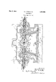
In the figure we have shown in vertical longitudinal section a valve chest mounted on a locomotive cylinder, only a portionof the cylinder being illustrated.
The section is taken throughthe portion of the chest in which the admission valves are located, it being understood that the exhaust chamber with its valves (which is not a part i of the present invention) is positioned alongside the admission chamber, the exhaust outlets being indicated at 2, 2. The chest 3, mounted on the cylinder 1, having a cam chamber drain 3a and cylinder lubricating pipe 3?), has aninlet 5 tothe steam cavity or chamber 6', andat itsends poppet admission valves 7, 8, one for each end of the cylinder, these valves being of annular construction-and-each having edges or flanges 9, 1.0,
adapted to seat, respectively, on the annular surfaces 11,12.
Normal closure of the valves to cut off the supply of steam to the inlet passages 18, 1a, [is effected by the steam pressure, be- 5 cause of the fact that the diameterand consequent effective area of the valve adjacent its flange 9 is greater than the diameter and consequent effective area of the valve adjacent itsifiange 10. Proper and rapid closure of the valves is further assured by the pressure of the steam on the outer ends of the valve stem members or rods 15, 16, on which stems the valves are mounted as by means of web members 17. Each valve has also a spring 18, adjustable by means of a screw and locknut 19, 19a, which bears against a ring or collar 20 mounted on the valve stem to insure seating of the valve when the locomotive throttle is closed.
Midway between the valves, within the housing structure 21 is a cam member 22, fixed as by a key or keys 23 on a shaft 24 positioned transversely of the chest. This shaft is adapted to be oscillated or rocked, through the intermediation of a suitable crank or arm (not shown), by the usual valve motion mechanism of the locomotive, for example by connection to the usual combination lever. The cam, which will be further described hereinafter, is thus rocked or os cillated, to control the valves through the valve stem members 15, 15a, and 16, 16a, with their respective rollers25 and 26. The parts or pieces 15, 15a, together form the complete stem or rod for valve 7, the portion 15 having an extension 27 slidable longitudinally in an opening or socket 27a in portion 15a, and the outer end of part 15a being adapted to abut against the shoulder 15b of the part 15. In like manner the parts 16, 16a, together formthe stem for valve 8, the extension 28 of part 16 sliding in the socket 28a in part 16a, and the end of part 16abeing adapted to abut against 9 shoulder 16?). The two stem members 15a, 1660, are in turn slidable longitudinally in the fixed bushings 29, 30.
Considered in another way, the left hand valve member may be said't-o comprise the valve proper 7 and the part 15, and the part 15a to be termed the rod or stem; and similarly the right valve member may be considered as comprising the valve proper 8 and the part 16, and the part 16a be considered as the stem.
Small auxiliary ports or passages 31, 32, extend from the steam chamber 6 through the housing. 21, and. the; respective bushings 29 and 30 down into the cylinder 4 at the points 31a and 32a, respectively. Suitable independent pockets or cavities 29a, 30a, and cavities 4b and 4c, are provided in bushings 29 and 30 and cylinder 4 in order to insure registry of the several portions of the respective passages 31, 32 upon assembly of the structure. Steam is admitted to the cylinder through these auxiliary passages 31 and 32 when the passages 3lband 32b in the respective stem members 15a and 16a are moved into registry therewith; A compres sion spring 33 is positioned between bushing 29 and flange 150 on the inner end of stem member 15a, and a similar spring 34 is positioned between bushing 30 and flange 160 of stem member 1611, these springs constantly exerting a pressure to. move their respective stem-members 15a and 16a inward toward the cam for the closing of the auxiliary, ports. 7 The peripheral surface of the cam member 22 has a low portion 37 and a high portion 35,-,and intermediate portions 36a and 36?). It willbe seen that in oscillation of the cam the rolle r.2 5 will engage or bear against surfaces 35, 36a and 37 in turn, or vice versa duringoppositemovement of 'the cam. The roller 26will. bear against the surfaces 35,
:Foiythe explanation of the operation of the complete device, let usnow assume that the piston 4a. is at the. left of cylinder 4 and is-about to move to the right, and that the valve motion; means of the locomotive is set to; give-a normal cut-off of about 50%. Dur- 50 ofthe pistons stroke, the roller 25 of valve 7 .willrbe'riding on surface 35 of cam 22, and. the cam, driven. by the usual valve. motion, will be completing its movement toithe left. and commence turning to the-fright. :During this time valve? will be heldwide open, the-stem portion 15a abutting-against the shoulder'15b of part 15. As
' the piston 4a moves farther to the right, to
the position'sho -wni'in full lines. on the drawing, andthe cam CO I1l3l1'lll6S to turn to the right, the rollerf25, will ride off of surface 35 ]ontQsurface 36aof'the cam,which is-the point of normal cut-ofhvalve 7 seating tight on thefse'ats 11,; 12. At this point, however, the stem; has! moved} far enough to the right to put passage 31?) in registrywithpassage 31 (whieh the position shown in. the drawilig) an steam-win be admittedthrough this auxiliary port, which will, ineflect, produce an extended cut-ofi' for starting, but which at high speeds Will be practically ineffective due to the low rate at which steam will pass through such a restrictedport. As the piston moves farther to the right and the cam continues its rotation, the roller 25, under the influence of spring 33, will ride onto surface 37 of the cam, for example, at 80. of stroke, and the. passage. 316 will be moved out of registry withpass'age 31," cutting oii steam entirely. This position of the lefthand valve stem is the one corresponding to that in which the right-hand valve stem is illustrated in the drawing.
lVhen the left valve has reached this position, i. e., with roller'25 riding on surface 37. of the cam, permitting closure both'of valve 7 and auxiliary port3l, the roller 26 of the right hand valve; 8 will start riding up on portion 36b of the cams surface, and the auxiliary port 32 will open, by virtue of the movement of passage 325 into registry therewith, and although the right end of the cylinder is normally on compression. at this time, there will be no preadmi'ssion throughpass'age 32 to cause excess pressure to be built up ahead of the-piston, because thepiston v4a will cover the port'32a, just as it is shown (in dotted lines) covering port 31a. on the return stroke. As the piston completes its stroke to the right, the cam 22-will turn until roller 26 of the right hand valve 8 rides on cam surface 35. The piston then moves to the left'and shortly thereafter the cam commences its reverse rotation, that is, to the left, until at 50% of the stroke the roller 26 rides down again on surface3'6b, seating valve8 to cause main cut-01f and movingpassage3'2b into registry withthe auxiliaryport'32' whichremains open (in the example underconsideration) until; the piston has moved of stroke. Asthe piston cam move farther to the left the roller-26;-rides down on cam surface 37',permitt-in-g movement; of't'he' portion 16a of the valve stem, under the influencetr; spring .34, which moves passage 32?; out of registry with auxiliaryport 32, closing said port fo r ioo the remainder of the-pi'st-ons stroke to the left, During said remainder of the stroke auxlllary port 3lwill again open, but prea'dm-ission or waste of steam'willbe prevented'bec'ause the 'outIetBIa-Of the port will be covered bythepiston, asshown in Y dotted lines atithe left.
'It is obvious that,--in carryingout our invention the: auxiliary port, inlets 31a and 32a are so positioned, with'relation tothecylinderends and. the movement ofthe pistomand of the pistons stroke in either direction it acts substantially as a supplemental valve to. close the auxiliary port at its lower end, even though the main valve stem has opened it at its upper end. Thus, the main valve stems 15a, 16a, and the piston 4a, form cooperating valve means for the ports 31 and 32.
Although the drawing illustrates the pres ent preferred embodiment of this invention it is obvious that modifications may be made without departing from the purview of the invention.
It will now be apparent that by our invention, involving but slight changes in the general arrangement of the poppet valves and valve chest, we are enabled to obtain, with such poppet valves having their advantage of quick movement between open and closed positions, the advantage of a very short limited cut-oil", and in addition the effect of a long cut-off for starting, without loss or preadmission of steam.
WVhat we claim is 1. In a steam engine, a cylinder, a main port and valve therefor, an auxiliary port and control means therefor, and cam means operating said valve and said control means, said control means including a member forming part of the stem for the main valve having a passage movable into and out of registry with the auxiliary port.
2. In a steam engine, a cylinder, a main port and valve therefor, an auxiliary port and control means therefor, and cam means operating said valve and said control means, said control means including a member forming part of the stem for the main valve having a passage movable into and out of registry with the auxiliary port upon movement of said cam means.
3. In a steam engine, a cylinder, a main port and valve therefor, an auxiliary port and control means therefor, and cam means operating said valve and said control means, said control means including a member forming part of the stem for the main valve having a passage movable into and out of registry with the auxiliary port and resilient means urging the member against said cam means.
4. In engine mechanism of the character described, a valve and valve stem, actuating means therefor, a main inlet port controlled by said valve, and an auxiliary inlet port controlled by said stem, said steam having a passage registrable with the latter port.
5. In combination, in a steam engine, a cylinder, a main inlet port therefor, an auxiliary inlet port, a valve member controlling the main port, a valve rod movably engaging said member and controlling it, and having a passage for controlling said auxiliary port, and actuating means associated with said rod including a cam having a plurality of actuating surfaces, one of which positions the rod to close both ports, another of which positions it to open the main port, and an intermediate of which positions the said rod to bring its passage into registry with said auxiliary port.
6. Valve mechanism comprising in combination a main port and a valve therefor, an auxiliary port, a two-piece valve controlling member, the parts of which have relative movement and one part of which has means to open and close said auxiliary port, and actuating means associated with said part of said member adapted to move it first independently of the other part of the member and then together therewith, the first movement moving the first-mentioned part of the member to open the auxiliary port and further. movement moving both parts of the member to close said port and open said valve, together with means causing a reversal of said movements in sequence upon reversal of movement of said actuating means.
7. Valve mechanism comprising in combination a main port and a valve therefor, an auxiliary port, a two-piece valve controlling member, the parts of which have relative movement and one part of which has means to open and close said auxiliary port, and actuating means associated with said part of said member adapted to move it first independently of the other part of the member and then together therewith, the first movement moving the first-mentioned part of the member to open the auxiliary port and further movement moving both parts of the member to close said port and open said valve, together with resilient means urging said first-mentioned part against said actuating means.
t 8. Valve mechanism comprising, in combination a main port and a valve therefor, an auxiliary port, a two-piece valve controlling member, the parts of which have relative movement and one part of which has means to open and close said auxiliary port, and actuating means associated with said part of said member adapted to move it first independently of the other part of the member and then together therewith, the first movement moving the first-mentioned part of the member to open the auxiliary port and further movement moving both parts of the member to close said port and open said valve, together Wth resilient means urging said firstmentioned part against said actuating means and means urging said second-mentioned part toward said first-mentioned part.
9. In a steam engine, a cylinder, a valve chest having a steam chamber, a plurality of main ports from said chamber to the cylinder and a valve means for each port, a plurality of auxiliary ports from the chamber to the cylinder, a reciprocable stem member for each of said valve means, having a steam passage, positioned so that upon movement of said member the passage Will move into and out ofregistry with an auxiliary port, and means between said stem members controlling their movement.
10. In a steam engine, a cylinder, a valve chest having a steam chamber, a'plurality of main ports from said chamber to the cylinder and a valve means for each port, a plurality of auxiliary ports from the chamber to the cylinder, a reciprocable stem member for each of said valve means, having a steam passage, positioned so that upon movement of said member the passage will'move into and out of registry with anauxiliary port, and means between said stem members controlling their movement comprising a rockmg cam.
11. In a steam engine,'a'cylinder, a valve chest having a steam chamber, a plurality of main ports from said chamber to the cylinder and a valve means for each port, a plurality of auxiliary ports from the chamber to the cylinder, a reciprocable stem member for each of said valve means, having a steam passage, positioned so that upon movement of said member the passage'will move into and out of registry with an auxiliary port, and means between said stem members controlling their movement comprising a cam having a low-face, a high face and a pair of intermediate faces, said intermediate faces provid-ing'for the uncovering of the auxiliary ports.
12.- In asteam-engine, a cylinder, a valve chest having a steam chamber, a plurality of mainports from said chamber to the cylinder-and a valve means for each port, a plur ality of auxiliary ports from the chamber tothe cylinder, a reciprccable stem member for each of said-valve means, having a steam passage, positioned so that upon movement of said member the passage willmove into and out of registry with an auxiliary port, and means between said stem members controlling their movement, comprising a cam having a low face, a high face, and a pair 'ofintermediate faces, said intermediate faces providing for the uncovering of the auxiliary ports,each stem member being adapted to engage in'sequence the highf'ace, an intermediate face, and the low face, and vice versa.
lntestimony whereof we have hereunto signed our names.
HUBERT J. TITUS.
JOHN S. WALLIS.
Priority Applications (1)
| Application Number | Priority Date | Filing Date | Title |
|---|---|---|---|
| US222815A US1907902A (en) | 1927-09-29 | 1927-09-29 | Steam engine |
Applications Claiming Priority (1)
| Application Number | Priority Date | Filing Date | Title |
|---|---|---|---|
| US222815A US1907902A (en) | 1927-09-29 | 1927-09-29 | Steam engine |
Publications (1)
| Publication Number | Publication Date |
|---|---|
| US1907902A true US1907902A (en) | 1933-05-09 |
Family
ID=22833808
Family Applications (1)
| Application Number | Title | Priority Date | Filing Date |
|---|---|---|---|
| US222815A Expired - Lifetime US1907902A (en) | 1927-09-29 | 1927-09-29 | Steam engine |
Country Status (1)
| Country | Link |
|---|---|
| US (1) | US1907902A (en) |
-
1927
- 1927-09-29 US US222815A patent/US1907902A/en not_active Expired - Lifetime
Similar Documents
| Publication | Publication Date | Title |
|---|---|---|
| US1907902A (en) | Steam engine | |
| US1816098A (en) | Steam driven fluid compressor | |
| US1177588A (en) | Engine-valve. | |
| US1401866A (en) | Steam-engine | |
| US1605657A (en) | Valve for steam engines | |
| US1376093A (en) | Steam-engine valve | |
| US1111983A (en) | Automatic exhaust-valve. | |
| US1869463A (en) | Poppet valve for steam distributing gears | |
| US825980A (en) | Automatic cut-off for reversible engines. | |
| US770671A (en) | Valve for engines | |
| US960615A (en) | Valve for engines. | |
| US1038261A (en) | Steam-engine or the like. | |
| US1201383A (en) | Steam-engine. | |
| US1106338A (en) | Steam-engine. | |
| US2155195A (en) | Adjustable thrust bearing for valve springs | |
| US678808A (en) | Combined compound and semicompound engine. | |
| US842985A (en) | Compound engine. | |
| US1337024A (en) | Steam-engine construction | |
| US513303A (en) | Duplex engine | |
| US1901571A (en) | Steam engine | |
| US1494994A (en) | Steam engine | |
| US671628A (en) | Steam-engine. | |
| US1241875A (en) | Steam-engine. | |
| US982395A (en) | Steam-engine with piston-controlled exhaust-ports. | |
| US1028631A (en) | Steam-engine. |