US1907699A - Buffer - Google Patents
Buffer Download PDFInfo
- Publication number
- US1907699A US1907699A US383324A US38332429A US1907699A US 1907699 A US1907699 A US 1907699A US 383324 A US383324 A US 383324A US 38332429 A US38332429 A US 38332429A US 1907699 A US1907699 A US 1907699A
- Authority
- US
- United States
- Prior art keywords
- cylinder
- buffer
- switch
- piston
- valve
- Prior art date
- Legal status (The legal status is an assumption and is not a legal conclusion. Google has not performed a legal analysis and makes no representation as to the accuracy of the status listed.)
- Expired - Lifetime
Links
- 239000000872 buffer Substances 0.000 title description 41
- 239000012530 fluid Substances 0.000 description 16
- 230000001276 controlling effect Effects 0.000 description 5
- 230000033001 locomotion Effects 0.000 description 4
- 238000010276 construction Methods 0.000 description 2
- 238000012856 packing Methods 0.000 description 2
- 230000001105 regulatory effect Effects 0.000 description 2
- 230000035939 shock Effects 0.000 description 2
- 241001052209 Cylinder Species 0.000 description 1
- 230000009172 bursting Effects 0.000 description 1
- 238000005266 casting Methods 0.000 description 1
- 230000006835 compression Effects 0.000 description 1
- 238000007906 compression Methods 0.000 description 1
- 239000000945 filler Substances 0.000 description 1
- 238000012986 modification Methods 0.000 description 1
- 230000004048 modification Effects 0.000 description 1
Images

Classifications
-
- B—PERFORMING OPERATIONS; TRANSPORTING
- B61—RAILWAYS
- B61L—GUIDING RAILWAY TRAFFIC; ENSURING THE SAFETY OF RAILWAY TRAFFIC
- B61L5/00—Local operating mechanisms for points or track-mounted scotch-blocks; Visible or audible signals; Local operating mechanisms for visible or audible signals
Definitions
- My invention relates to buffers and particularly to buffers for use with spring operated switches.
- Another object of my invention is to provide means inthe' cylinder casing of the buffer for controlling the transfer of the operating fluid from one side of the piston to the other side thereof during the operation of the piston. e it Another object of my invention is to -provide a buffer with adjustable means for regulating the speed at which the piston thereof returns to its normal position.
- Another object of my invention is to pro vide a buffer havingits parts so arranged that the return stroke of the piston is controlled by the suction of fluid into the cylinder, thus eliminating heavy pressure against the joints and thereby obviating the possibilityof leakage of the fluid used as a filler.
- Another object of this invention is to provide a buffer which is adapted to be used for either a left-hand or a right-hand switch by simply removing the cover and transferring the valve assembly from one end to the other I end of the buffer.
- Another object of my invention is to provide a cover for the buffer which is of such construction that the cover will always indicate the location of the valve, whether the buffer is assembled for left-hand or righthand operation of a switch.
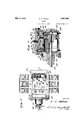
- Fig. l is a plan view of my improved buffer as applied to a spring railroad switch.
- Fig. 2 is a top View of my buffer with the cover removed.
- Fig. 3 is a sectional view taken on line 3-3 of Fig. 2.
- 10 and 11 designate the points of aspring switch. These points are yieldingly held in the position shown in Fig. 1 by the spring 12, thus allowing a train moving downwardly from the single track to pass onto the track to its right. 1
- the compression of the spring 12 permits the switch points 10 and 11 to be moved to i the left by the wheels of a car going in the 90 oFF Icsf A contains a plurality of thread-ed ports 28 and opposite direction, that is, onto the single track, thus allowing the car to pass through the switch.
- the spring 12 operates the switch points to their normally closed position, so that a car moving in the clownward direction will always take the track to its right.
- I provide a buffer 13 which permits the switch to open freely but which retards the closing of the switch sufficiently to permit a train to pass therethrough before the switch is allowed to close, and which is capable of being adjusted so as to allow the switch to close at the desired speed as soon as the train passes therethrough, thus obviating the wear and tear on the switch points which occur with the ordinary spring switch.
- the buffer 13 comprises a cylinder 14 having therein a piston 15 which is connected to one end of the piston rod 16, the other end of the rod 16 being operatively connected through suitable connections to the switch points 10 and 11.
- Suitable packing 17 is provided around the rod 16 where it passes through the cylinder head 18', the packing being held in place by the adjustable nut 19.
- the cylinder 14 is normally filled with oil,,and arranged above it is an oil reservoir 21 having passages 24 and 25 provided in its bottom which communicate with the cylinder 14.
- One of these passages is controlled by the valve 26 which is yieldingly held in its closed position by the springs 27 and which iscapable of being opened by the pressure of the fluid during the travel of the piston 15 toward the end of the cylinder containing the valve 26.
- the bottom of the oil reservoir 21 also 29 which cmmunicate with the cylinder 14 and which are capable of receiving screw plugs 30-. These ports are so arranged that after the beginning of the travel of the piston during, itsv return stroke, oil will be drawn down, by, suction from the reservoir 21' first in a small quantity and then in a graduallyv increasing quantity, until the piston passes the opened ports so that in operation the speed of the piston will be. slow at first and then gradually increased until it has passed a certain point, and then at practically uniform speed until the switch points are in, their normal position. The length of time theswitch points are held open and the speed of the return stroke of the piston are.
- the valve 26 and the springs 27' are assembled with the plate 31 by means of the screws 32.
- Recesses 33 and 34 are provided in one end of the upper portion of the buifer cast ing to receive the plate 31, when the valves are in the position shown in the drawings and recesses 35 and 36 are provided in the other end to receive the plate 31 when the valve is transferred to the other end of the bufler.
- the plate 31 is held in position by the cover 37 when the buffer is in its assembled condition.
- the cover 37 is'provided with a projection or lug 38 which is capable of entering the recesses 33 and 34 or 35 and 36 depending on the location of the plate 31 containing the valve assembly. As this lug cannot enter the recesses containing the plate 31,
- the opposite end of the cover must always be placed over the valve and, in order to determine the location of the valve after the cover has been placed on the buifer, the end of the cover which is over the valve is preferably marked with the word valve. It will therefore be seen that if the plate 3 1 containing the valve assembly is transferred to the recesses 35 and 36 it will be necessary to reverse the cover, so that the lug 38 will enter the recesses 33 and 34.
- the boss 39 on the under side of the cover 37 surrounding the hole 40v extends below the portion 41 so that air will be trapped in the spaces 42 during the filling of the buffer with oil so that it will be impossible to completely fill the buffer with oil.
- This feature is important so as to provide sufficient space to accommodate the piston rod 16 when it is moved to its innermost position should the fluid be placed in the buffer with the piston rod in its outermost position and therefore prevents the possibility of bursting the cylinder which otherwise might occur if it were possible to completely fill the cylinder 14 and reservoir 21 with oil when the piston rod 16 is in, its outermost position.
- the under side of the cover is also provided with ribs 43 which engage the top of the plugs 30 and therefore prevent theseplugs from working out of the ports 28 and 29.
- the bu-ifer When the buffer is to be installed for operating a switch which'i's normally in the position indicated in the drawings, the bu-ifer is assembledwith the valve 26 and, plugs 30 in the position indicated in the drawings.
- the piston rod is then connected through suitable connections to the'switch points 10 and 11 and the buffer is mounted on the ties as indicated so that when the switch points 10 and 11 are fully thrown to their open position, the piston 15 will be moved to the position indicated in dotted lines in Fig. 3.
- the buffer After the buffer has been mounted on the ties, it is nearly filled with a suitable oil, but leaving the heads of the plugs exposed, and the cover is bolted lightly in position and a train is passed through the switch. If the buffer does not hold the switch open between wheels the plug 30 in the uppermost port 29 is transferred to the uppermost port 28, as viewed in Fig. 2 of the drawings. If the buffer still does not hold the switch open between wheels the plug is transferred from the next port 29, from the top, to the port 28 next to the other plug. If necessary all the plugs 30 may be transferred from the holes 29 to the holes 28 in order to obtain the desired adjustment.
- the cover should be bolted down securely and the buffer should be filled with oil.
- the spring will cause the piston to uncover the ports 28 in succession and therefore after the initial movement of the piston the suction of the oil through the ports 28 will be increased until the piston passes this group of ports and thereafter at uniform speed, thus returning the switch points 10 and 11 to their normally closed position at a speed for which the buffer has been previously adjusted.
- a fluid bufi'er comprising, a cylinder,
- imperforate piston adapted-to reciprocate within said cylinder, a reservoir adjacent said cyl nder, said reservoir hav ng an unrestr1ct-- edpassage in one end and a valve controlled.
- a fluid buffer comprising a cylinder, a piston adapted to reciprocate within said cylinder, a reservoir, adjacent said cylinder and having passages and a'plurality of ports adjacent each end thereof communicating the reservoir with the cylinder,- a valve for con-:
- a fluid buffer comprising'a cylinder,-a
- a piston adapted to reciprocate Within said cyl-s inder, a reservoir adjacent said cylinder hav- 1ng a passage and a plurality of ports W113; cent each end thereof for communicating the reservoir with the cylinder, a valve; seat ad jacent each of said passages, a valve assembly operatively mounted within one of said. seats and adapted to be transferable as a u'nitto the other seat toprovide a buffer effective. in an opposite direction and transferable, plugs for a plurality of said ports.
- a buffer for a springswitch comprising a cylinder, an imperforate piston in said cyl-- inder, means for connecting said piston to the spring switch, said piston being capable of moving freely upon the operation ,ofthe switch from its normal position,.
- a bu ffer comprising a cylinder, a recipe rocatable piston within said cylinder, a reservoir ad acent said cyhnder and havingpassages communicating therewith, a valve a'ssembly capable of being transferredto selecassembly adapted to control one of said passages: when the" bufier isassembled for right hand operation and adapted to control the other passages when thebuffer isassembled for left-hand operation, a cover for said buffer, and means associated with said cover adapted to indicate the location of the valve assembly.
- a fluid bufler comprising a cylinder, a: reciprocatable piston within said cylinder, areser'voir having passages and a plurality of ports communicating with each end of the cylinder and adjustable means within said reservoir adapted' to close certain of said ports to govern the transfer'of the fluid between the cylinder and the reservoir and a valve as sembly capable of being transferred to selectively control either of said passages.
- a fluid buffer comprising a cylinder, a piston capable of reciprocating within said cylinder, a reservoir adjacent said cylinder, said reservoir having aplurality of passages and ports communicating with said cylinder to provide means for by-passing fluid from one end of the piston to the other end thereof, fl'uid'within said cylinder and said reservoir, avalve assembly capable of'being transferred to selectively control either of said passages, said valve adapted to'open upon the move ment of' the piston in one direction and to close upon the movementof the piston in the opposite direction and adjustable means Wholly within said reservoir adapted to regulate the flow of fluid between the reservoir" and the cylinder when the aforementioned valve isin its closedposition.
- a fluid buffer comprising a cylinder, a piston reciprocatively mounted within said cylinder, a reservoir adjacent said cylinder and having passages communicating with each end? of said cylinder, valve seats adjacent said passages and a valve assembly selectively positioned in one of said seats for controlling one of said passages.
- a fluid buffer comprising a cylinder, a reservoir adjacent said cylinder and having a passage communicating with each end therer of, a valve for selectively controlling one of said passages, and a piston reciprocatively mounted 'within the cylinder adapted to move freely in one direction when the valve is controllingone-passage and to move freely in the opposite direction when the valve is controlling the other passage, thereby adapting the buffer to a right hand or a left hand buffer by:transferringthevalve;
Landscapes
- Engineering & Computer Science (AREA)
- Mechanical Engineering (AREA)
- Fluid-Damping Devices (AREA)
Description
May 9, 1933.
C. A. ALDEN BUFFER Filed Aug. 5, 1929 2 Sheets-Sheet l C. A, ALDEN BUFFER Filed Aug. 3, 1929 2 Sheets-Sheet 2 Patented May 9, 1933 UNITED STATES PATENT COMPANY, A CORPGEATION OF PENNSYLVANIA BUFFER Application filed August 3, 1929. Serial No. 383,324.
My invention relates to buffers and particularly to buffers for use with spring operated switches.
In connection with switches for use in trackage where a single track leads into a double track it is necessary to provide some sort of a spring switch which will enable trains going in one direction to always take the proper track and which will permlt trams going in the opposite direction to pass through without permanently changmg the position of the switch, so that as soon as the train has passed through, the switch Wlll automatically return to its normally closed position to take care of a train going in the first-mentioned direction.
Heretofore it has been the practice to provide ordinary spring switches for opposing the opening of the switch points from their normally closed position and for automatical- 1y closing the points when they are opened by the passage of a train therethrough onto the single track. y
The principal objection to this type of switch is that immediately after each set of wheels has passed beyond the switch points, the switch points are thrown back to their normally closed position and have to be operated again by the next set of wheels as they pass through the switch. This causes considerable wear and tear on the switch points each time a long train passes through the switch.
It is therefore the object of my lnvention toprovide a buffer for the spring-switch which will operate to prevent the closing of the switch points during the passage of a train therethrough and which Wlll permit the switch points to close as rapidly as desired without shock as soon as the train has passed beyond the switch.
Another object of my invention is to provide means inthe' cylinder casing of the buffer for controlling the transfer of the operating fluid from one side of the piston to the other side thereof during the operation of the piston. e it Another object of my invention is to -provide a buffer with adjustable means for regulating the speed at which the piston thereof returns to its normal position.
Another object of my invention is to pro vide a buffer havingits parts so arranged that the return stroke of the piston is controlled by the suction of fluid into the cylinder, thus eliminating heavy pressure against the joints and thereby obviating the possibilityof leakage of the fluid used as a filler.
Another object of this invention is to provide a buffer which is adapted to be used for either a left-hand or a right-hand switch by simply removing the cover and transferring the valve assembly from one end to the other I end of the buffer.
Another object of my invention is to provide a cover for the buffer which is of such construction that the cover will always indicate the location of the valve, whether the buffer is assembled for left-hand or righthand operation of a switch.
The novel features of my invention will be more fully understood from the following description and claims taken with the drawings in which:
Fig. l is a plan view of my improved buffer as applied to a spring railroad switch. I
Fig. 2 is a top View of my buffer with the cover removed. I
Fig. 3 is a sectional view taken on line 3-3 of Fig. 2.
Referring to the drawings, 10 and 11 designate the points of aspring switch. These points are yieldingly held in the position shown in Fig. 1 by the spring 12, thus allowing a train moving downwardly from the single track to pass onto the track to its right. 1
The compression of the spring 12 permits the switch points 10 and 11 to be moved to i the left by the wheels of a car going in the 90 oFF Icsf A contains a plurality of thread-ed ports 28 and opposite direction, that is, onto the single track, thus allowing the car to pass through the switch. Upon the passage of the car through the switch the spring 12 operates the switch points to their normally closed position, so that a car moving in the clownward direction will always take the track to its right.
In order to retard the closing of the switch points each time a set of wheels passes through the switch, and in order to permit the closing of the points without shock after the train has passed therethrough, I provide a buffer 13 which permits the switch to open freely but which retards the closing of the switch sufficiently to permit a train to pass therethrough before the switch is allowed to close, and which is capable of being adjusted so as to allow the switch to close at the desired speed as soon as the train passes therethrough, thus obviating the wear and tear on the switch points which occur with the ordinary spring switch.
The buffer 13 comprises a cylinder 14 having therein a piston 15 which is connected to one end of the piston rod 16, the other end of the rod 16 being operatively connected through suitable connections to the switch points 10 and 11. Suitable packing 17 is provided around the rod 16 where it passes through the cylinder head 18', the packing being held in place by the adjustable nut 19.
The cylinder 14 is normally filled with oil,,and arranged above it is an oil reservoir 21 having passages 24 and 25 provided in its bottom which communicate with the cylinder 14. One of these passages is controlled by the valve 26 which is yieldingly held in its closed position by the springs 27 and which iscapable of being opened by the pressure of the fluid during the travel of the piston 15 toward the end of the cylinder containing the valve 26.
The bottom of the oil reservoir 21 also 29 which cmmunicate with the cylinder 14 and which are capable of receiving screw plugs 30-. These ports are so arranged that after the beginning of the travel of the piston during, itsv return stroke, oil will be drawn down, by, suction from the reservoir 21' first in a small quantity and then in a graduallyv increasing quantity, until the piston passes the opened ports so that in operation the speed of the piston will be. slow at first and then gradually increased until it has passed a certain point, and then at practically uniform speed until the switch points are in, their normal position. The length of time theswitch points are held open and the speed of the return stroke of the piston are.
regulated to the required degree by the ma nipulation ofthe plugs 30 after the installav tion of the buffer.
The valve 26 and the springs 27' are assembled with the plate 31 by means of the screws 32. Recesses 33 and 34 are provided in one end of the upper portion of the buifer cast ing to receive the plate 31, when the valves are in the position shown in the drawings and recesses 35 and 36 are provided in the other end to receive the plate 31 when the valve is transferred to the other end of the bufler. The plate 31 is held in position by the cover 37 when the buffer is in its assembled condition. By this construction all that is necessary, in order to change the buffer to adapt it for operation in the opposite direction from that shown in the drawings, is to remove the cover 37 and lift the plate 31,
containing the valve assembly, out of the recesses 33 and 34 and place it in recesses 35 and 36 thus placing the valve 26 in position to control the opening 25 instead of the opening 24. a
The cover 37 is'provided with a projection or lug 38 which is capable of entering the recesses 33 and 34 or 35 and 36 depending on the location of the plate 31 containing the valve assembly. As this lug cannot enter the recesses containing the plate 31,
the opposite end of the cover must always be placed over the valve and, in order to determine the location of the valve after the cover has been placed on the buifer, the end of the cover which is over the valve is preferably marked with the word valve. It will therefore be seen that ifthe plate 3 1 containing the valve assembly is transferred to the recesses 35 and 36 it will be necessary to reverse the cover, so that the lug 38 will enter the recesses 33 and 34. The boss 39 on the under side of the cover 37 surrounding the hole 40v extends below the portion 41 so that air will be trapped in the spaces 42 during the filling of the buffer with oil so that it will be impossible to completely fill the buffer with oil. t
This feature is important so as to provide sufficient space to accommodate the piston rod 16 when it is moved to its innermost position should the fluid be placed in the buffer with the piston rod in its outermost position and therefore prevents the possibility of bursting the cylinder which otherwise might occur if it were possible to completely fill the cylinder 14 and reservoir 21 with oil when the piston rod 16 is in, its outermost position.
The under side of the cover is also provided with ribs 43 which engage the top of the plugs 30 and therefore prevent theseplugs from working out of the ports 28 and 29. I
When the buffer is to be installed for operating a switch which'i's normally in the position indicated in the drawings, the bu-ifer is assembledwith the valve 26 and, plugs 30 in the position indicated in the drawings. The
piston rod is then connected through suitable connections to the'switch points 10 and 11 and the buffer is mounted on the ties as indicated so that when the switch points 10 and 11 are fully thrown to their open position, the piston 15 will be moved to the position indicated in dotted lines in Fig. 3. After the buffer has been mounted on the ties, it is nearly filled with a suitable oil, but leaving the heads of the plugs exposed, and the cover is bolted lightly in position and a train is passed through the switch. If the buffer does not hold the switch open between wheels the plug 30 in the uppermost port 29 is transferred to the uppermost port 28, as viewed in Fig. 2 of the drawings. If the buffer still does not hold the switch open between wheels the plug is transferred from the next port 29, from the top, to the port 28 next to the other plug. If necessary all the plugs 30 may be transferred from the holes 29 to the holes 28 in order to obtain the desired adjustment.
After the desired action of the switch has been attained, the cover should be bolted down securely and the buffer should be filled with oil.
In operation, with the switch points 10 and 11 in their normally closed position and the piston in the buffer as indicated in full lines in the drawings, a train passing through the switch onto the single track will operate the points to compress the spring 12 and at the same time to move the piston 15 to the position indicated in dotted lines in Fig. 3. The movement of the piston 15 to this position will cause the valve 26 to be opened and the oil in one end of the cylinder to be trans-- ferred freely around the piston to the other end of the cylinder through the medium of the reservoir. As the return of the oil around the piston is very small during the initial movement of the piston in its return stroke, due to the fact that the valve 26 is closed and the ports 28 are either covered by the piston 15 or are to the right thereof, as viewed in the drawings, the switch points are not allowed to close during the time required for the passing of each set of wheels of a train therethrough, as any tendency on the part of the switch to close would not be rapid enough to allow the switch to close before it is engaged by the next set ofwheels. As soon as the train has passed through the switch, the spring will cause the piston to uncover the ports 28 in succession and therefore after the initial movement of the piston the suction of the oil through the ports 28 will be increased until the piston passes this group of ports and thereafter at uniform speed, thus returning the switch points 10 and 11 to their normally closed position at a speed for which the buffer has been previously adjusted.
While I have shown my invention in but one form, it will be obvious to those skilled in the art that it is not so limited, but is susceptible of various other changes and modifications without departing from the spirit thereof,and-I desire, therefore, that only. such limitations: shall. be placed thereupon as, are
imposed by the prior art oras are specificallyset forth in the appended claims, f
Having thus described my. invention what Iclaim as new and desireto secure by Letters Patent is:
1. A fluid bufi'er comprising, a cylinder,
imperforate piston adapted-to reciprocate within said cylinder,a reservoir adjacent said cyl nder, said reservoir hav ng an unrestr1ct-- edpassage in one end and a valve controlled.
passage, in the other end and a plurality of ports adjacent each end thereof adapted ,to communicate'the reservoir with the cylinder and a valve for controlling the valve con:
trolled passage; V 1
2. A fluid buffer comprising a cylinder, a piston adapted to reciprocate within said cylinder, a reservoir, adjacent said cylinder and having passages and a'plurality of ports adjacent each end thereof communicating the reservoir with the cylinder,- a valve for con-:
trolling one of said passages and plugs for a plurality of said ports. 7
3. A fluid buffer comprising'a cylinder,-a
piston adapted to reciprocate Within said cyl-s inder, a reservoir adjacent said cylinder hav- 1ng a passage and a plurality of ports W113; cent each end thereof for communicating the reservoir with the cylinder, a valve; seat ad jacent each of said passages, a valve assembly operatively mounted within one of said. seats and adapted to be transferable as a u'nitto the other seat toprovide a buffer effective. in an opposite direction and transferable, plugs for a plurality of said ports.
4;. A buffer for a springswitch comprising a cylinder, an imperforate piston in said cyl-- inder, means for connecting said piston to the spring switch, said piston being capable of moving freely upon the operation ,ofthe switch from its normal position,.a reservoir adjacent the cylinder, a cover for said reser: voir, fluid in said reservoir and saidcylinder and adjustable means between said cylinder and said reservoiradaptedto regulatethe op;- erative speed of the piston during the return I.
movementof thegswitch toinormal position said means being locked against adjustment. while the cover is ln-its-assembled position.
5. A bu ffer comprising a cylinder, a recipe rocatable piston within said cylinder, a reservoir ad acent said cyhnder and havingpassages communicating therewith, a valve a'ssembly capable of being transferredto selecassembly adapted to control one of said passages: when the" bufier isassembled for right hand operation and adapted to control the other passages when thebuffer isassembled for left-hand operation, a cover for said buffer, and means associated with said cover adapted to indicate the location of the valve assembly. I
7. A fluid bufler, comprising a cylinder, a: reciprocatable piston within said cylinder, areser'voir having passages and a plurality of ports communicating with each end of the cylinder and adjustable means within said reservoir adapted' to close certain of said ports to govern the transfer'of the fluid between the cylinder and the reservoir and a valve as sembly capable of being transferred to selectively control either of said passages.
8; A fluid buffer, comprising a cylinder, a piston capable of reciprocating within said cylinder, a reservoir adjacent said cylinder, said reservoir having aplurality of passages and ports communicating with said cylinder to provide means for by-passing fluid from one end of the piston to the other end thereof, fl'uid'within said cylinder and said reservoir, avalve assembly capable of'being transferred to selectively control either of said passages, said valve adapted to'open upon the move ment of' the piston in one direction and to close upon the movementof the piston in the opposite direction and adjustable means Wholly within said reservoir adapted to regulate the flow of fluid between the reservoir" and the cylinder when the aforementioned valve isin its closedposition.
9. A fluid buffer comprising a cylinder, a piston reciprocatively mounted within said cylinder, a reservoir adjacent said cylinder and having passages communicating with each end? of said cylinder, valve seats adjacent said passages and a valve assembly selectively positioned in one of said seats for controlling one of said passages.
10; A fluid buffer comprising a cylinder, a reservoir adjacent said cylinder and having a passage communicating with each end therer of, a valve for selectively controlling one of said passages, and a piston reciprocatively mounted 'within the cylinder adapted to move freely in one direction when the valve is controllingone-passage and to move freely in the opposite direction when the valve is controlling the other passage, thereby adapting the buffer to a right hand or a left hand buffer by:transferringthevalve;
In: testimony whereof I hereunto aflix my signature; 7
CHARLES A. ALDEN.
Priority Applications (1)
| Application Number | Priority Date | Filing Date | Title |
|---|---|---|---|
| US383324A US1907699A (en) | 1929-08-03 | 1929-08-03 | Buffer |
Applications Claiming Priority (1)
| Application Number | Priority Date | Filing Date | Title |
|---|---|---|---|
| US383324A US1907699A (en) | 1929-08-03 | 1929-08-03 | Buffer |
Publications (1)
| Publication Number | Publication Date |
|---|---|
| US1907699A true US1907699A (en) | 1933-05-09 |
Family
ID=23512615
Family Applications (1)
| Application Number | Title | Priority Date | Filing Date |
|---|---|---|---|
| US383324A Expired - Lifetime US1907699A (en) | 1929-08-03 | 1929-08-03 | Buffer |
Country Status (1)
| Country | Link |
|---|---|
| US (1) | US1907699A (en) |
-
1929
- 1929-08-03 US US383324A patent/US1907699A/en not_active Expired - Lifetime
Similar Documents
| Publication | Publication Date | Title |
|---|---|---|
| US1704817A (en) | Locomotive-cylinder cock | |
| US1907699A (en) | Buffer | |
| US3791534A (en) | Valve apparatus for controlling train action | |
| US1689841A (en) | Shock absorber | |
| US1903775A (en) | Air spring and cushion | |
| US1908504A (en) | Apparatus for controlling railway switches | |
| US2316930A (en) | Railway switch operating apparatus | |
| US1734795A (en) | Valve-gear control | |
| US2559477A (en) | Switch machine for railroads | |
| ES370542A1 (en) | IMPROVEMENTS IN THE CONSTRUCTION OF PROTECTIVE DEVICES AGAINST SKATING OR SLIDING FOR RAILWAY VEHICLES. | |
| US1805631A (en) | Fluid pressure brake device | |
| US1466342A (en) | Valve mechanism for dump cars | |
| US2061752A (en) | Railway switch operating apparatus | |
| US1742407A (en) | Door-control device | |
| US1704320A (en) | Automatic air-brake lock | |
| US2401120A (en) | Railway switch operating apparatus | |
| US1039555A (en) | Dash-pot. | |
| US795693A (en) | Air-brake apparatus. | |
| US1192331A (en) | Apparatus for the control of fluid-pressure brakes. | |
| US2373517A (en) | Railway switch operating apparatus | |
| US2598495A (en) | Railway switch operating apparatus | |
| US2243801A (en) | Electric control valve mechanism | |
| US1337255A (en) | Ginia | |
| US928837A (en) | Dumping-car. | |
| US1179521A (en) | Speed-controlling device. |