US1907662A - Automobile top - Google Patents
Automobile top Download PDFInfo
- Publication number
- US1907662A US1907662A US570319A US57031931A US1907662A US 1907662 A US1907662 A US 1907662A US 570319 A US570319 A US 570319A US 57031931 A US57031931 A US 57031931A US 1907662 A US1907662 A US 1907662A
- Authority
- US
- United States
- Prior art keywords
- cover
- vehicle
- bow
- seat
- storage chamber
- Prior art date
- Legal status (The legal status is an assumption and is not a legal conclusion. Google has not performed a legal analysis and makes no representation as to the accuracy of the status listed.)
- Expired - Lifetime
Links
Images


Classifications
-
- B—PERFORMING OPERATIONS; TRANSPORTING
- B60—VEHICLES IN GENERAL
- B60J—WINDOWS, WINDSCREENS, NON-FIXED ROOFS, DOORS, OR SIMILAR DEVICES FOR VEHICLES; REMOVABLE EXTERNAL PROTECTIVE COVERINGS SPECIALLY ADAPTED FOR VEHICLES
- B60J7/00—Non-fixed roofs; Roofs with movable panels, e.g. rotary sunroofs
- B60J7/08—Non-fixed roofs; Roofs with movable panels, e.g. rotary sunroofs of non-sliding type, i.e. movable or removable roofs or panels, e.g. let-down tops or roofs capable of being easily detached or of assuming a collapsed or inoperative position
- B60J7/10—Non-fixed roofs; Roofs with movable panels, e.g. rotary sunroofs of non-sliding type, i.e. movable or removable roofs or panels, e.g. let-down tops or roofs capable of being easily detached or of assuming a collapsed or inoperative position readily detachable, e.g. tarpaulins with frames, or fastenings for tarpaulins
- B60J7/102—Readily detachable tarpaulins, e.g. for utility vehicles; Frames therefor
- B60J7/104—Fastening means for tarpaulins
Definitions
- Another principal object is to enable the .15 entire top to be folded and compactly stored in the Ivehicle by provision in the storage chamber of suitable tracks or guides designed to control the stored'poslition of the to i Inother principal object ⁇ is to provide a top having the aforesaid advantages which may be alternately secured in placeover the front seat of a Vehicle or over both the front and rear seats thereof.
- Another principal object of the invention is to provide a top frameV which may .be readilyextended when itis desired to mount the-top, and ⁇ as readily collapsed .when it is desired to store thesame;
- Figure 3 is a fragmentary, longitudinal, cross-sectional view of a vehicle showingthe track arrangement for the frame of the ,to i
- I Figure 4 is a similar View showing the top .in place over the front seat ofthe vehicle;
- Figure 5 is a fractional elevation of a vehicle showing the top Iin place over the front seat' -L
- Figure 6 shows one of the sidecurtains Ause dgin my construction
- Figure, ⁇ 8 s a fractional, longitudinal, cross-sectional view of a vehicle in which the top is shown covering the front and back seats of the vehicle;
- Figure 9 is a side elevation of the same;
- Figure 10 is a plan view -of the vehicle in which the ⁇ top is shown in position overthe front seat, part of the top havingv been broken awayf s
- Figure ll ⁇ is asimilar viewto.
- Figure ⁇ 10 except that thetop extends over both lthe forward and rear seats ofthe vehicle;
- Figure l2 shows the arrangement of the ,55 side curtains; n F igurel represents the coverV of the storage chamber for thetop; i 1
- Figure 14 is; an ⁇ elevation -of'a top supporting rod;vand p Figurey l5 is a cross-section .taken along the line 15-15 of Figure 14, looking in the direction of the-arrows.
- y g Referring now in detail to the. drawings in which similar Ycharacters refer to similar parts throughout, 16v represents .a vehicle havin doors 17 and y18 and a windshield 19. eats are shown at 20, 2l as well as the seatgrbacks 22 and ⁇ 23, all of which are conventional withpresentmotor car construction.
- E l In Figure l the vehicletop isshown stored in the storagec'hamber 24 where the'top is adapted to beV kept when vnot in use.
- Tracks 25v are provided in the storage chamber 24 to permit the convenient :folding ,of the top in stored condition. These tracks are a continuationv of the tracks 26 in which the supports for the top are adapted tofslide andbe locked in position, as will be hereinafter described.
- t n 1 By reference to Figure 4, it will be seen that the cover 29 of the vehicle top is in position over the forward or drivers seat of the vehicle and doesnot extend over the rear seat thereof. This .cover is fastened at its forward end to the yframe 31 of the windshieldpl9, by ⁇ buttons 32 or other convenient fastening,1as,shown in Figure 10.
- the bow 36 is provided with ⁇ telescopic rods 42. These lrods are splined with the bow and' slide in the-recesses 43 in the legs ofthe bow., and. are adapted to be secured in adjusted position therein by the locking screw 44.
- the bow. 35 is. supported by brackets on the legs of the bow 36, the said'zbow 35 being hinged to brackets at 46.
- af bow 48 is provided to support the top as shown, the legs. of said bow vbeing adjustable in the slotted brackets 49 and set therein: by the thumb-screws 50.
- the rods 420i? the bow 36 ( Figure 1.4)v are provided with T-ends51 adapted to slide in the'chan- -nelled tracks 26and be retained therein by the flanges 53 of said tracks.
- the bow 35 is then swivelled upward as far as it will go and locked 1n position to the link 37, such lockingv being done by manipulation of the winged nut 41, the link 37 being clamped to the windshield 31.
- the frame of the top is thus held in iirm condition as a unitary' structure.
- the top is withdrawn from the storage chamber 24 as alreadyv described and the T-ends 51 of therod 42 are moved along the tracks 26 until they lodge in the recesses 55.
- the rear cover 29 is then fastened behind. the rear seat of the car and the bows 35 and36. are secured in position in the same manner as already described with reference, to the mounting ofthe top for the front seat only.
- a supplemental vcover 47 is then secured at 57 in any convenient manner to the front of the cover 29 just described, and the'forward end of this; supplemental cover is secured tothe windshield 31 in the same manner.
- a vsupplemental bow 48 is provided to support the supplemental cover 47, said bowbeing held ini po- -sition by the slotted brackets 49 in cooperation with the-lock screws 50.
- the lock screws 50 are loosened andthe bow .48 is allowed toslide down the brackets 49, assuming a stored position in the storage chamber 24.
- a vehicle to-p comprised of a cover and a collapsible frame, in combination with a vehicle body having front and rear seats and a storage chambelr,'guides in said storage chamber, extending forwardly and rearwardly therefrom means on the frame for connecting said frame in operablerelationship with said guides and adapting said frame tobeV moved in said guides to storage position in said storage chamber and to supappended port the frame and cover in mounted position over the front or rear seat as desired, and means for securing said frame in position when mounted.
- an automobile body having afront seat, a collapsible rear seat, a stora e chamber disposed immediately behind sald front seat, a pair of channel guides disposed in said chamber and extending forwardly and rearwardly therefrom, and a vehicle top comprised of a cover and a collapsible rame, said collapsible frame comprising a bow having its ends disposed in said channel guides' and movable therealong to support the frame and cover in mounted position over the front seat or rear seat as def sired or to storage position in said storage chamber.
Landscapes
- Engineering & Computer Science (AREA)
- Mechanical Engineering (AREA)
- Seats For Vehicles (AREA)
Description
May 9, 1933.
A. J. PINTO 1,907,662
AUTOMOBILE TOP Filed Oct. 22, 1931 6 Sheets-Sheet 1 ATTORNEY Me/VM May 9, 1933.
INVENTOR ATTORNEY maa/M A. J. PINTO AUTOMOBILE TOP May 9, 1933.
Filed Oct. 22, 1931 6 Sheets-Sheet 3 0 O O O O O IINVENTOR W/M May 9, 1932.. A. J, PINTO 1,907,662
AUTOMOBILE TGP Filed OCh. 22; 1931 6 Sheets-Sheet 4 INVENTOR ATTORNEW m wrm May 9, 1933. I A. J, P|NTO 1,907,662
AUTOMOBILE TOP Filed Oct. 22. 1931 6 Sheets-Sheet 5 'lr v INVENTOR BY ATTORNEY A. J. PINTO AUTOMOBILE TOP May 9, 1933.
Filed Oct. 22, 1931 6 Sheets-Sheet 6 \||.llJ|L..|I||J u n n INVENTOR @n ATToRN/W/ wrm Patented May 9, 1933 A UNITED STATES ANGELO J. PINTO, oF EosEBANK, NEW YTroni:
AUTOMOBILE TOP Application filed October 22, 1931.7 Serial No. 570,319.`
@ parts whether the same is in mounted position or in storage, with means for holding the same frigid to the vehicle-in which it is used when mounted in position.
Another principal object is to enable the .15 entire top to be folded and compactly stored in the Ivehicle by provision in the storage chamber of suitable tracks or guides designed to control the stored'poslition of the to i Inother principal object` is to provide a top having the aforesaid advantages which may be alternately secured in placeover the front seat of a Vehicle or over both the front and rear seats thereof. f
25 Another principal object of the invention ,is to provide a top frameV which may .be readilyextended when itis desired to mount the-top, and` as readily collapsed .when it is desired to store thesame;
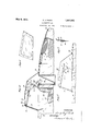
. Other objectsof the invention will be apparent from reading this specification in connection with the accompanying `drawings, in which Figure l is a fractional, longitudinal, cross-sectional view of the body of a vehicle embodying my invention;
' Figure 2 shows the vehicle top in packe condition in the storage chamber provided therefor; v
Figure 3 is a fragmentary, longitudinal, cross-sectional view of a vehicle showingthe track arrangement for the frame of the ,to i
IFigure 4 is a similar View showing the top .in place over the front seat ofthe vehicle;
Figure 5 is a fractional elevation of a vehicle showing the top Iin place over the front seat' -L Figure 6 shows one of the sidecurtains Ause dgin my construction;
'The rear portion of this cover is simi- Figure 7 is a detail showing the method of fastening the side curtains t`otheltopf; s
Figure,` 8],s a fractional, longitudinal, cross-sectional view of a vehicle in which the top is shown covering the front and back seats of the vehicle;
Figure 9 is a side elevation of the same; j Figure 10 is a plan view -of the vehicle in which the` top is shown in position overthe front seat, part of the top havingv been broken awayf s Figure ll `is asimilar viewto. Figure `10 except that thetop extends over both lthe forward and rear seats ofthe vehicle;
Figure l2 shows the arrangement of the ,55 side curtains; n F igurel represents the coverV of the storage chamber for thetop; i 1
Figure 14 is; an` elevation -of'a top supporting rod;vand p Figurey l5 is a cross-section .taken along the line 15-15 of Figure 14, looking in the direction of the-arrows. y g Referring now in detail to the. drawings in which similar Ycharacters refer to similar parts throughout, 16v represents .a vehicle havin doors 17 and y18 and a windshield 19. eats are shown at 20, 2l as well as the seatgrbacks 22 and` 23, all of which are conventional withpresentmotor car construction. E l InFigure l the vehicletop isshown stored in the storagec'hamber 24 where the'top is adapted to beV kept when vnot in use. Tracks 25v are provided in the storage chamber 24 to permit the convenient :folding ,of the top in stored condition. These tracks are a continuationv of the tracks 26 in which the supports for the top are adapted tofslide andbe locked in position, as will be hereinafter described. t n 1 By reference to Figure 4, it will be seen that the cover 29 of the vehicle top is in position over the forward or drivers seat of the vehicle and doesnot extend over the rear seat thereof. This .cover is fastened at its forward end to the yframe 31 of the windshieldpl9, by `buttons 32 or other convenient fastening,1as,shown in Figure 10.
37 to said bow 35 when the desired angular relationship between the two has been determined.
The bow 36 is provided with` telescopic rods 42. These lrods are splined with the bow and' slide in the-recesses 43 in the legs ofthe bow., and. are adapted to be secured in adjusted position therein by the locking screw 44. The bow. 35 is. supported by brackets on the legs of the bow 36, the said'zbow 35 being hinged to brackets at 46. In: Figure 8 the cover 29 isshown in position.l over the rear seat instead ofl over the forward seat only, as shown in lFigure 4, the only difference in the mounting being that therear end of the top is fastened-behind the rear seat of the vehicle instead ofbehind the front seat of the vehicle, as just described, and the forward end of said topv portion is secured to thel supplemental cover section 47 which in turn issecured tofthe windshield frame 31 in a similar. manner as has been shown withl reference to the positionof the top Ysection as shown in Figure 4.'
In the all-over construction shown in Figure 8, af bow 48 is provided to support the top as shown, the legs. of said bow vbeing adjustable in the slotted brackets 49 and set therein: by the thumb-screws 50. The rods 420i? the bow 36 (Figure 1.4)v are provided with T-ends51 adapted to slide in the'chan- -nelled tracks 26and be retained therein by the flanges 53 of said tracks.
The operation of my invention is as ollows. "Whenl the top is not-in use, it is stored in the chamber 24 which is provided for that purpose, the T-rods 42 of the bow 36 being held in the tracks 25 of the storage chamber 24, one of such tracks being located at each side of the storage chamber longitudinal with the car. p
vWhen. desired to put up the top, the same is withdrawn from the storage chamber 24, Y the T-rods 42 are moved along thel tracks 25 until the T-ends 51 rest in the recesses 541er 55. For the present, we will assume that it is desired to erect the top so vas to cover the forward seat of the automobile only.v In this case the T-endsy 51 of the. rods 42 rest in the recess 54. The rear cover 29'isrthen fastened behind thedrivers seat 33-'and the forward end of this cover is fastened to the upper frame 31 of the windshield. The bow 36 is then extended on the rod 42 to hold the cover 29 in taut condition and the lock screw 44 is manipulated to hold the rod 42 and bow 36 in integral condition. The bow 35 is then swivelled upward as far as it will go and locked 1n position to the link 37, such lockingv being done by manipulation of the winged nut 41, the link 37 being clamped to the windshield 31. The frame of the top is thus held in iirm condition as a unitary' structure.
Assuming now that it is desired to extend the top over both seats of the vehicle shown in the drawings, the top is withdrawn from the storage chamber 24 as alreadyv described and the T-ends 51 of therod 42 are moved along the tracks 26 until they lodge in the recesses 55. The rear cover 29 is then fastened behind. the rear seat of the car and the bows 35 and36. are secured in position in the same manner as already described with reference, to the mounting ofthe top for the front seat only. A supplemental vcover 47 is then secured at 57 in any convenient manner to the front of the cover 29 just described, and the'forward end of this; supplemental cover is secured tothe windshield 31 in the same manner. A vsupplemental bow 48 is provided to support the supplemental cover 47, said bowbeing held ini po- -sition by the slotted brackets 49 in cooperation with the-lock screws 50. When not4 in use, the lock screws 50 are loosened andthe bow .48 is allowed toslide down the brackets 49, assuming a stored position in the storage chamber 24. v i
lVhen the top is in mountedy positionVside curtains 58, 59 and 60 are buttoned or otherwise secured in place. The detail of this fastening is shown in Figure 7 where aflap 61 is shown on the cover 29 (or 47. where it f is the supplemental cover), forming a pocket 62 in which the topr marginal edges. of the side curtains (or 58 or 59) are'secured in such manner as t0 prevent rain from entering between the side curtainsandY the top cover.
I have described what I believe to be-the best embodiment ofv my invention. I do not wish to be limited, however, in patent' protection to the embodiment shown andl described, but what I desire to cover by Leti ters Patent is setforth in the claims.
I claim:
1. A vehicle to-p comprised of a cover and a collapsible frame, in combination with a vehicle body having front and rear seats and a storage chambelr,'guides in said storage chamber, extending forwardly and rearwardly therefrom means on the frame for connecting said frame in operablerelationship with said guides and adapting said frame tobeV moved in said guides to storage position in said storage chamber and to supappended port the frame and cover in mounted position over the front or rear seat as desired, and means for securing said frame in position when mounted.
2. In combination, an automobile body having afront seat, a collapsible rear seat, a stora e chamber disposed immediately behind sald front seat, a pair of channel guides disposed in said chamber and extending forwardly and rearwardly therefrom, and a vehicle top comprised of a cover and a collapsible rame, said collapsible frame comprising a bow having its ends disposed in said channel guides' and movable therealong to support the frame and cover in mounted position over the front seat or rear seat as def sired or to storage position in said storage chamber. y
In testimony whereof I have an'Xed my signature to this specification.
ANGELO J. PINTO.
Priority Applications (1)
| Application Number | Priority Date | Filing Date | Title |
|---|---|---|---|
| US570319A US1907662A (en) | 1931-10-22 | 1931-10-22 | Automobile top |
Applications Claiming Priority (1)
| Application Number | Priority Date | Filing Date | Title |
|---|---|---|---|
| US570319A US1907662A (en) | 1931-10-22 | 1931-10-22 | Automobile top |
Publications (1)
| Publication Number | Publication Date |
|---|---|
| US1907662A true US1907662A (en) | 1933-05-09 |
Family
ID=24279177
Family Applications (1)
| Application Number | Title | Priority Date | Filing Date |
|---|---|---|---|
| US570319A Expired - Lifetime US1907662A (en) | 1931-10-22 | 1931-10-22 | Automobile top |
Country Status (1)
| Country | Link |
|---|---|
| US (1) | US1907662A (en) |
Cited By (1)
| Publication number | Priority date | Publication date | Assignee | Title |
|---|---|---|---|---|
| US2686076A (en) * | 1952-09-06 | 1954-08-10 | Harry E Helser | Convertible automobile body |
-
1931
- 1931-10-22 US US570319A patent/US1907662A/en not_active Expired - Lifetime
Cited By (1)
| Publication number | Priority date | Publication date | Assignee | Title |
|---|---|---|---|---|
| US2686076A (en) * | 1952-09-06 | 1954-08-10 | Harry E Helser | Convertible automobile body |
Similar Documents
| Publication | Publication Date | Title |
|---|---|---|
| US3649068A (en) | Adjustable sleeve for sun visors | |
| US2483478A (en) | Automobile tent | |
| US1894233A (en) | Automobile attachment | |
| US3236557A (en) | Folding top structure | |
| US2252716A (en) | Automobile visor and rear vision mirror support construction | |
| US1907662A (en) | Automobile top | |
| US1426129A (en) | Disappearing automobile top | |
| US3055700A (en) | Vehicle door | |
| US1446833A (en) | Convertible automobile body | |
| US1910075A (en) | Top for automobile rumble seats | |
| US1306836A (en) | Jacques m | |
| US1412474A (en) | Windshield | |
| US2012193A (en) | Collapsible automobile bed | |
| US1707121A (en) | Rumble-seat inclosure | |
| US1800514A (en) | Convertible body for motor vehicles | |
| US2619376A (en) | Windscreen for automobiles | |
| US1817577A (en) | Windshield and support therefor | |
| US2058806A (en) | Top for automobile rumble seats | |
| US1944053A (en) | Cover for rumble seats of automobiles | |
| US1447062A (en) | Sun and rain shield for automobile tops | |
| US1442624A (en) | Windshield for vehicles | |
| US1269073A (en) | Combination vehicle-top. | |
| US1298122A (en) | Automobile-top. | |
| US2029676A (en) | Folding flexible roof or curtain | |
| US1422431A (en) | Combination back and side curtain |