US1906339A - Conveyer system - Google Patents
Conveyer system Download PDFInfo
- Publication number
- US1906339A US1906339A US454976A US45497630A US1906339A US 1906339 A US1906339 A US 1906339A US 454976 A US454976 A US 454976A US 45497630 A US45497630 A US 45497630A US 1906339 A US1906339 A US 1906339A
- Authority
- US
- United States
- Prior art keywords
- article
- conveyer
- articles
- station
- group
- Prior art date
- Legal status (The legal status is an assumption and is not a legal conclusion. Google has not performed a legal analysis and makes no representation as to the accuracy of the status listed.)
- Expired - Lifetime
Links
- 230000007246 mechanism Effects 0.000 description 71
- 230000000153 supplemental effect Effects 0.000 description 8
- 230000003134 recirculating effect Effects 0.000 description 6
- 238000005266 casting Methods 0.000 description 5
- 238000010276 construction Methods 0.000 description 5
- 230000000694 effects Effects 0.000 description 4
- NEHMKBQYUWJMIP-UHFFFAOYSA-N chloromethane Chemical compound ClC NEHMKBQYUWJMIP-UHFFFAOYSA-N 0.000 description 2
- 230000005484 gravity Effects 0.000 description 2
- 238000000034 method Methods 0.000 description 2
- 230000000717 retained effect Effects 0.000 description 2
- 241000382509 Vania Species 0.000 description 1
- 239000000654 additive Substances 0.000 description 1
- 230000000996 additive effect Effects 0.000 description 1
- 230000002301 combined effect Effects 0.000 description 1
- 230000000881 depressing effect Effects 0.000 description 1
- HDRXZJPWHTXQRI-BHDTVMLSSA-N diltiazem hydrochloride Chemical compound [Cl-].C1=CC(OC)=CC=C1[C@H]1[C@@H](OC(C)=O)C(=O)N(CC[NH+](C)C)C2=CC=CC=C2S1 HDRXZJPWHTXQRI-BHDTVMLSSA-N 0.000 description 1
- VKYKSIONXSXAKP-UHFFFAOYSA-N hexamethylenetetramine Chemical compound C1N(C2)CN3CN1CN2C3 VKYKSIONXSXAKP-UHFFFAOYSA-N 0.000 description 1
- 230000000977 initiatory effect Effects 0.000 description 1
Images


Classifications
-
- B—PERFORMING OPERATIONS; TRANSPORTING
- B65—CONVEYING; PACKING; STORING; HANDLING THIN OR FILAMENTARY MATERIAL
- B65G—TRANSPORT OR STORAGE DEVICES, e.g. CONVEYORS FOR LOADING OR TIPPING, SHOP CONVEYOR SYSTEMS OR PNEUMATIC TUBE CONVEYORS
- B65G47/00—Article or material-handling devices associated with conveyors; Methods employing such devices
- B65G47/34—Devices for discharging articles or materials from conveyor
- B65G47/46—Devices for discharging articles or materials from conveyor and distributing, e.g. automatically, to desired points
- B65G47/48—Devices for discharging articles or materials from conveyor and distributing, e.g. automatically, to desired points according to bodily destination marks on either articles or load-carriers
- B65G47/482—Devices for discharging articles or materials from conveyor and distributing, e.g. automatically, to desired points according to bodily destination marks on either articles or load-carriers using exclusively mechanical transmitting means between destination marks and switching means
Definitions
- This invention relates to a method of conveying, to a conveying system and to apparatus suitable for use in such system, and has for some of its several objects to provide for the expeditious conveying of cars or other articles to a number of stations or operation points of a system, to provide for recirculation of articles which have passed the station or operation points for which they are destined in such a Way as to present these articles again to such stations or operation points without causing congestion of the c onveying system as a whole, to provide 1mproved car or article selecting mechanism f or determining the path of the cars or articles throughout the system, to provide improved mechanism for selectively transferring cars or articles from one conveyer to another conveyer of the system and to provide improved selective mechanism forxremoving cars or articles from a procession being conveyed, to provide construction of stations or operation points adapted to receive cars thus removed and to provide an improved method of supplying cars or other articles to intended stations or operation points.
- Fig. l is a diagrammatic plan view of a conveying system embodying my invention.
- Figs. 2 and 3 are side and end elevations respectively of a car suitable to be used as one of several circulating articles in the system;
- Figs. 4a and 4b are plan yiews of adj oiningl portions of the conveying system shown in Fig. 1, and together show one group of six stations, Fig. 4a showing that part of one group of the system lying between the lines 4-4 and 4**--4a of Fig. 1, and Fig. 4b showing that part of the same group lying between the lines 4**-4B and 4"-4h of Fig. 1;
- Figs. 5n and 5b are side elevations of those portions of the system shown in Figs. 4a and 4b respectively;
- Fig. 6 is a section on the line 6-6 of Fig. 4e;
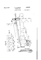
- Fig. 7 is a fragmentary side elevation of the car of Fig. 2, on a larger scale, and showing also in elevation a fixed upright post carcontacts;
- Fig. 9 is a view similar to Fig. 8, showing the movable contacts moved by enga ement with the stationary article selector into a position wherein the movable abutment actuated thereby may engage an article removing hook adapted to remove the car from the conveyer;
- Fig. 1() is a lan view of the article removing mechanism of a given station or 0peration point, superpose parts of the cone veyer being eliminated in this view to show the hook resetting mechanism below the platform of the station;
- Fig. 11 is a fragmentary side elevation of the hook resetting mechanism of Fig. 10;
- Fig. 12 is a fragmentary side elevation of the treadle shown in Figs. 10 and 11;
- Fig. 13 is a plan view on an enlarged scale of one run of the conveyer included between the lines 13 and 13a of Fig. 4"L and provided with article-transfer mechanism, for instance that indicated at 20 in Fig. 1, parts of the conveyor being broken away to illustrate certain structure lying below the conveying belt of the '"ru'n; @if
- Fig. 14 is a fragmentary vertical sectional View on the line 14-14 of Fig. 13;
- Fig. 15 is a fragmentary horizontal sectional view taken onthefiline 15-15 of Fig. 14;
- Fig. 16 is a fragmentary sectional view taken on the line 16-16 of Fig. 15;
- Fig. 17 is a fragmentary sidel elevation taken on ,theflinefr-lT-Flof Fig.'13and showing in dotted lines the engagement of a movngers, l
- Fig. 18 is a plan view of another type of station.
- Figs. 19 and 20 are fragmentary side elevations of a car adapted for use with such station.
- the conveying system shown diagrammatically in Fig. 1 as an illustrative and preferred embodiment of my invention includes a conveyer A which may be of any type, but is here illustrated as a belt running in the direction of arrows R, and comprising if desired a number of belt sections adapted successively to carry the conveyed articles.
- a number of stations or operation points are located adjacent the conveyer; for example, in Fig. 1, stations 1, 2 and 3" are provided.
- My invention provides for the supply of articles to stations or operation points which may be arranged in one or more groups, the stations being located for instance according to a logical grouping of the operations to be performed upon the conveyed articles or a convenient arrangement of machinery used in performing sequential operations upon the conveyed article.
- stations l, 2a and 3 are shown as grouped along conveyer A, the
- roup which includes these stations being designated as group A.
- group I Associated with such a group I provide a supplemental conveyer B moving in the direction of the arrows S opposite to that of the above described conveyer A.
- Such supplemental conveyer B may serve as an intra-group conveyer for serving certain stations of a group which may advantageousl be disposed along this conveyer rather t an alon the primary conveyer A.
- a supplemental conveyer B may serve as an intra-group conveyer for serving certain stations of a group which may advantageousl be disposed along this conveyer rather t an alon the primary conveyer A.
- Fig. 1 For examp e, in Fig. 1,-stations 4a, 5 and 6'L forming part of group A are disposed along conveyer B and are served thereby.
- suitable transfer mechanism diagrammatically indicated at 20 is provided or transferring articles from conveyer A to conveyer B in position to be presented to the stations 4a, 5 and 6"L served by conveyer B.
- other transfer mechanism indicated at 21 is preferably provided. Such a.
- conveying system therefore permits of supplying articles to stations located along two oppositely moving conveyers and further permits articles transferred from primary conveyer A to supplemental conveyer B to be hereafter returned to primary conveyer
- a second group designated asgroup B and comprising stations 1", 2b, 3", 4b, 5b and 6 having associated therewith a supplemental conveyer B is provided.
- conveyer A is eX- tended to, and preferably past, this group.
- the supplemental conveyers B of the one group need not constitute a continuation of the corresponding supplemental conveyeror conveyers of the other group or groups, conveyer A being adapted to effect the necessary inter-group conveying.
- a single continuous conveyer B serves as a supplemental conveyer for the various groups, with the resulting capability of use as a primary conveyer for inter-group conveying.
- inter-group conveying may be effected concurrently in opposite directions.
- transfer of conveyed articles from one conveyer to another for presentation to predetermined stations is preferably effected selectively in accordance with predetermined characteristics imparted to the conveyed articles.
- a suitable construction of the transfer mechanisms 20 and 2l of the one or more groups, adapted to this mode of selective transfer is described hereinafter.
- articles thus recirculated are not conveyed in such circulatory movement over the entire conveying system, which may be very extensive, but are recirculated merely within the have passed their intended stations and must be again presented thereto, nor are groups in the system congested by the passage there- 19 a second or subsequent time to a Cal through or the recirculation therein of articles which are on their way to be presented station which they have once passes(
- articles thus recirculated are not conveyed in such circulatory movement over the entire conveying system, which may be very extensive, but are recirculated merely within the have passed their intended stations and must be again presented thereto, nor are groups in the system congested by the passage there- 19 a second or subsequent time to a Cal through or the recirculation therein of articles which are on their way to be presented station which they have once passes(
- the transfer mechanism employed in transferring articles from one belt to the other for presentation to a station on the latter' belt is employed, and the transfer of an article from one belt to the other belt for the purpose of recirculation is effected in the same manner as the transfer of oneI article to the otherfor the purpose of initially presenting it to a lstation on the second belt.
- the selective transfer mechanism for instance transfer mechanism 2O situated at the end of a group, is adapted to respond to all articles having a characteristic common to the group.
- transfer mechanism' is provided at opposite ends of the i group (preferably as explained above, the .same transfer mechanism employed in transferring articles initially carried by one conveyer' to stations on the opposite conveyer),
- an article intended for station 1a maybe placed on conveyer A at point H and conveyed thereby to at station 1 is able to perform' the desired operati-on upon the article, the operator may so alter the contact mechanism of the article as to determine-its subsequent transport to any other desired station, for instance, station 2b of group ticle is subsequently'transported by'conveyer A past thetransfer mechanism 2O which is nowr non-responsive to the B' group char.- acteristic of thev article, and thence to the station 1?. If the operator- B. In this instance the arintended station.
- the operator I is unable or not ready to perform the intended operation uponthe article, or if, in case the article is to be removed from the conveyer at station 1, it can not at the time be thus removed, the article will pass station 1, proceed to the transfer mechanism 20 which is responsive to it, be transferred to ⁇ conveyer B, be conveyed thereby which is also responsive to it, be returned ⁇ thereby to conveyer A and again presented to the intended station 1, such recirculating of the article taking place any desired or necessary number of times.
- Such recirculation of articles may take place in the case of all articles destined for any of the stations of group A, for example an article destined for station 5a will proceed along conveyer A to transfer mechanism 20 which is responsive to its group A characteristic and thereafter be presented by conveyer B to station 5, either with or Without subsequent recirculation Within group A. After reaching station 5 the article may be removed from the conveyer or may either immediately or after being returned to the conveyer have its group characteristic altered to determine subsequent transport of the article to another station of another group.
- the transfer mechanism which serves to transfer such articles after passing their'initially destined station to the conveyer which conveys them to the group of the second intended station' preferably is responsive to articles having the characteristic common to the-second group to .which articles are to be conveyed.
- conveyer A is to constitute the primary inter-group conveyer with belt B functioning mainly as a supplemental intragroup conveyer to supply those stations not adjacent to belt A and to recirculate arto transfer mechanism 21 roo ticles within groups,-the one or more transfer mechanisms 21 serving to return articles from conveyer B to conveyer A should be responsive to articles having not only the group istics (for recirculation in group A) or group B characteristics (for subsequent transport by conveyer A to group B).
- my invention in one aspect is concerned with presenting the conveyed articles to various stations or operation points, the system provides also for ⁇ the carrying away of articles from these various stations and conveying them to other stations of the system' or to suitable delivery points which in the present instance are indicated by reference characters K and L on conveyers A and B respectively.
- the carrying away of articles may follow immediately their presentation to the intended stations, the articles either passing continuously the stations for which they are destined or pausing if necessary while the desired operations are performed upon them.
- my invention in certain aspects contemplates the removal of the conveyed articles at the stations for which they are destined and, if desired, their subsequent replacement upon the conveyer and further transport thereby.
- means for selec-tively removing articles from the adjacent conveyer is provided at each of the stations, a specific form of such means being describedL hereinafter.
- the articles conveyed such as the cars of Fig. 2
- the articles conveyed are provided with contact mechanism prearranged to cooperate with the article removing mechanism of one or more stations to initiate the removal of the articles.
- Such article-carried contact mechanism mav advantageouslv be the same as that employed for initiating thetransfer of articles from one convever to the other. for instance, in order to supply stations served by belt B with articles initiallv conveyed by belt A, or in recirculating articles for successive presentation to astation.
- the contact mechanism carried by the articles is arranged to provide each article conveyed with predetermined group and station characteristics so that articles may be conveyed to the intended group and station as directly as possible.
- the prearranfred group characteristic of the article regulates the order of travel of the article over the conveyers by selectively ⁇ actuating' the transfer mechanisms, while thel combination of the group and station characteristics of the article determines the station at which the article is removed.
- the article-removing -mechanism is arranged to allow articles to pass without re-' moval when ⁇ desired, or when the particular station-can not receive further articles.
- the conveying belts A and B are preferably carried on elevated framework indicated generally by the reference character 30.
- These stations which may. serve either as operation points, for instance as work benches, or asl sources of supply for other conveyers or entirely separate machinery, preferably comprise platforms 3l extending to the side of the adjacent belt so that articles may easily be transferred b sliding or rollingy from the belt to the platfbrm.
- a guard rail 32 may be provided at ⁇ the side of the platform opposite the belt to retain articles on the platform.
- the platforms 31 preferably slant down from the adjacent belt so that articles which once begin to leave the belt may be moved y the force of gravity entirely off the belt and will slide into contact with the guard rail 32.
- article removing mechanism Any desired forni of article removing mechanism may be employed, if desired, to remove the conveyed articles from the belt.
- article removing mechanism which comprises a pivoted hook 33 normally extending into the path of articles moving on the adjacent conveyer belt and adapted to ,be swung about its' pivot shaft 34 by articles with which it engages into a nondeflecting position wherein it clears succeeding articles on the conveyer.
- articles conveyed are provided with abutments of which a preferred construction is described hereinafter) suitablel to engage with the hooks
- the article is then constrained to move in the general path of an arc about the shaft through this path by the combined effect of gravity and the tractive force of the conveyer or forward momentum of the article:
- Preferably means are provided for yieldingly retaining the article removing hook normally in a deflecting position to draw articles from the belt. Referring to Fig. 6, the shaft 34 on which the hook 33 is fixed is mounted in a bearing 35 substantially normal to the sloping platform 31.
- a spring 38 fastened to any fixed part of the framework, for instance to the angle bar 39.
- This yielding means for retaining the article-removing hook in a deilecting position is preferably arranged to be effective only during a portion of the movement of the hook from its deflecting position.
- the arrangement of a spring 38 and arm 36 with respect to the shaft 34 is such that when the hook 33 isl in its normal position ready to engage articles on the belt, the arm 36 lies on one side .f the pivot shaft 34.
- the force of the spring 38 is not strong enough to prevent the rotation of the hook 33 about the pivot shaft 34 under the influence of the 34 and is moved Lacassearticle being removed.
- Suitable mechanism is preferably provided for returning the hook 33 toits article re,-l
- such means- is provided in the form of a treadle 40 (Figs. 10, 11 and 12) pivotally mounted to the frameworkv of the platform at 41 and connected by .a rod 42, a bell-crank arm 43 and a rod 44 to a link45 (Figs. 6 and 11.) loosely mounted on the pivotal shaft 34.V
- ardownwardly extending end 46 of rod 44 lies in the plane of movement of the arm 36 which is fixed on shaft 34.
- the rod 44 and its depending' end 46 may be moved tothe left in Figs. 10 and 11, the end 46 of shaft 44 ing to swing the shaft 34 and hook 33 in a clockwise direction whereby the hook 33 is returned, to its article removing position.
- each -of the stations may be for example ⁇ of suflicient size Vto hold two of the cars, one car dotted lines 5() in Fig. 4t at the left of the station, while another car occupies the position shown in dotted lines50 adjacent to the first car.
- a car occupying Ithe position indicated at 50 will still be engaged bythe article removing hook 33, and will obstruct the return of the hook to a deflecting position until removed.
- one article, such as a car may be retained on the are being operated upon,while another similar car or other article isretained on the platform in a position readily accessible to the operator.
- any suitablel selective mechanism may be employed to determine and regulate the path of travel of the articles, and, incase the articles are to be removed from the conveyer as explained above, to determine at what points they are removed, preferable mechanism for these purposes will now be described.
- the articles conveyed are herein shown as cars provided with racks 61 for carrying shoes.
- the car is provided with a movable abutment, herein shown as a'pin 70 depending from an arm 71 which is fixed to a vertical rotatable shaft 72 sup orted by brackets 73 and 74, the movable a utment being adapted to cooperate with car removing mechanism, such for exengaging the arm 36 and serv-vv being able to occupy the position shown inample as the hooli'33 described above to ef- 'fect removal of the car from the conveyer.
- suitable yielding means such for exam le as the spring 75 is provided for normal y urging thev arm 71 in a clockwise direction and hold-- *ing it in a position such as shownin Fig. 8 to the right and tends to hold the hook in capable of being adjusted so that and station characteristics and.
- a group o openings 78 is provided'near the top of the shaft, with ⁇ any one of which openmgs the fes'l upper linger 76 ⁇ may be engaged.
- These upper. ⁇ openings on the shaft corresponding to 'various groups of a possible arrangement of the conveyer system and the upper finger 76 thus constitute a contact, the position of which impartsthe desired group character-h istie to the car.
- a lower group of openings 79 is preferably provided, the low-- er finger 77 being engageable with any of these openings to e retained thereby in any desired vposition of vertical adjustment.
- the lower finger 77 constitutes a station contact, imparting to the car4 thev desired station characteristic.
- Stationary selector means positioned at various points at the side of the conveyers are'provided, capable of cooperating with the contact mechanism carried by the car or otherv conveyed article to cause the movable abutment 7 0 to be moved into operative positionI to .engage an article-removing hook' 33, or as explained hereinafter, to engage ac tuating'means for the car transfer mechanism.
- this vertical shaft may be part of a car-'removing mechanism at one of the individual stations, in which case an upper group selector finger 91 is adjustably mounted at a predetermined level to contact with van article-carried con'- tact corresponding to the group in which this selector mechanism is located.
- a station selector finger 92 is likewise adjustably mounted at a lower level in position to contact witha station contact corresponding to the station at which this selector mechanism is located.
- o eration of the movable abutment is effecte only by the successive'contacting ofthe respective pairs of contacts and selector'fingers.
- the group contact 76 of the car rst'enga es the stationary group selector finger 91, ollowing whichthe'station contact 77 of the car engages the station selector finger 92, engagement of both of these pairs of cooperating elements being necessary to move the movable' abutment into operative position'.
- This'result may be obtained by disposing the car-carried contacts 76 and 77 at an angle to each other, and disposing the selector fingers at a similar angle to each other, as shown in Figs. 8 and 9.
- the car or other articleconveyed is preferably provided with an abutment for engaging the transfer mecl1' anism which serves to remove the cars from one belt, for instance -belt A, and place them on the opposite belt.
- this abutment comprises a pin 100 depending from a fixed bracket 101 on the rear right Referring to Figs.
- avpreferred mechanism for transferring articles from onebelt to the other and which may be utilized as the transfer mechanisms 20 and 21 provided in the system explained above includes a deflector finger 102 fixed to a vertical shaft 103 which'is pivotally mounted in a fixed casting 104, fitted between the runs of the conveyer, the defiector finger 102 being positioned as shown in Fig. 14 slightly above the level of the conveyer belts.
- this deflector nger 102 indicated in dotted lines in Fig. 13
- the abutment 100 carried by an article passes the deflector finger 102 without making contact. therewith and the article to v which the ab .utment is attached continues along its previous path.
- Atoothed wheel 105 (Figf13) fixedv to a shaft 107 within a recess ferring to Fig. 106 to receive 100 of an artic is provided 106 in the casting 104.
- the recess 106 is open at the fixed deflector abutment le and is open at 106" to perkmit the'disengagement of this abutment, the
- One wall 106c of the recess is disposed in the form of an arc to pro vide an arcuate path for abutments 100 in contact with the toothed wheel pon movement of the deflector finger 102 into its outer and (perative position as shown in Fig. upon a movin this defiector contact with one of 105.
- This swinging coupled with the pull upon the article by the conveyer which thus receives the article-carried arcuate path ⁇ a article, serves to move the deflector abutment 100 in an long the curved wall 106y of the recess'in the casting 104 thus forcing the toothed wheel 105 to rotate.
- the article-carried abutment 100 becomes disengaged therefrom and is drawn out through the side opening 106b pull of the conveyer upon the article.
- selective mechanism is preferably provided for causing the deilector to be actuated by articles having predetelrmined group and stationcharacteristics.
- the selective mechanism for transferring articles includes also a vertical shaft 140 similar to Fig. 7 and previously described in connection with the mechanism for causing removal of articles at respective stations.
- any desired arrangement of selector fingers is provided vso that upon the engagement of predetermined group and station contacts of an article with corresponding group and station selector fingers on the vertical shaft 140, the movable abut ment 70 of Vthe article will strike and move the arm 13S to operate the deflector finger 10'2 and eHect transfer of the article to the oppo-p ⁇ site conveyer.
- the vertical selector-finger supporting shaft 140 associated with the transfer mechanism of a group is provided with 65 a'group selector finger in the position correupon the transfer mechanism spendingA to that group, t0 e-lect transfer of articles of that grou vidng a larger-num r ofvgroup selector iingers, for instance by adding a group selector finger as indicated by dotted lines 1n Fi 7,
- the transfer mechanism may berendere responsive to articles having group characteristics of other groups. For instance incase articles are to be sent from any stations 4, 5 or 6a of group A to a station in group B, and group A. 's to function as a recirculating unit for articles having group Acharacteristics, transfer mechamsm group Amay have both A and B group selector fingers. i
- a non-mterference mechanism shown in Figs. 4a and 4h as applied to opposite ends of a roup of stations, comprises a stop 150 mova le by the engagementvof an arm 151 with afpassing ⁇ article into a postion iii the path of succeeding articles to prevent their passage.
- the article which has ⁇ engaged with arm 151 may then be transferred by the transferV mechanism 21 to the opposite conveyer without danger of being struck by succeeding articles.
- In-its movement in the opposite direction upon f or instance conveyer B such transferred article engages a pivoted trip 152, moving this trip out of the path of the article, and releasA ing a latch 153 to which it is connected by a link 154'.
- the stop 150 isthen free to move under the iniiuencel of a suitable spring 155 to an inoperative position to permit succeeding articles to pass without interruption.
- the stop and article-engaging arm 150 and 151 respectively are duplicated upon the opposite conveyer at 156 and 157 respectively, the opposite arms and stops being interconnected as shown so thatthe actuation of stop 150 by the arm 151 also serves to actuate the stop 156 thus to prevent passage of articles past this stop 156 on the opposite conveyer B. In this Way an article which is being transferred from 'onveyer A to conveyer B will not colli-de with an' artlcle moving straight I the opposite conveyer,
- the mechanism previously described includes a car having casters thereon but it has been found that cars with Hat bottoms and no casters may he used in which case it has been found advisable to provide the stations with casters and in some instances with guide rollers to facilitate the movement of the cars thereon.
- Such a. construction is illustrated in Figs. 18 and 19 of the drawings. '.In Fig. 18 the station platform 31 has thereon casters 200 on which the cars rest while guide rollers 201 are mounted upon the guard rail 32 and project over the platform.
- Conveying mechanism comprising a conveyer, means for selectively removing therefrom at a point thereon articles having predetermined group and station characteristics corresponding to said point, means for selectively diverting from the conveyer articles having the same predetermined group characteristic after passing said article-removing means, and article-recirculating means for returning articles thus diverted to said conveyer in position again to be presented to said article-removing means.
- Conveying' ⁇ mechanism comprising a conveyer, means for selectively removing therefrom at a point thereon articles having predetermined group and station characteristics corresponding/to said point, means for selectively diverting from the conveyer articles having the said predetermined group characteristic, article-recirculating means for returning articles thus diverted to said conveyer in position again to be presented to said article-removing means, and means for selecstops 150 and 156 to f article-recirculating at length in connection with the descrip- -group of stations,
- Conveying m-echanism comprising a conveyer, means or selectively removing thererom at a point thereon articles having predetermined group and station characteristics corresponding to said point, means for selectively diverting from the conveyer articles 'having the said lpredetermined group characteristic, article-recirculating means for returning articles thus diverted to said conveyer yin position againto be presented to said article-removing means, and means lfor selectively removing from said article-recirculating means at a point thereon articles having predeterminedv roup and station characteristics correspon ing to said point.
- Conveying mechanism comprising a conveyer Afor presenting articles to a group of stations, means at said respective stations for selectively removing article having predetermined station characteristics corresponding to the respective stations and having a predetermined group characteristic corresponding to the group of stations, means for selectively diverting from thefconveyer articles having the said predetermined group characteristic which have passed certain stations, means for carrying ar-I ticles thus, diverted past another station and returning them to said conveyer in rear ofl said first-named stations.
- IConveying mechanism comprising a conveyer for presenting articles to a group of stations, means at said respective stations for removing articles having predetermined station characteristics corresponding to y"the respective stations and having a predetermined group characteristic corresponding to the means for selectively diverting from the conveyer articles having the same predetermined group characteristic which have passed certain stations, means for carrying articles thus diverted past another station, means at said last-named station for selectively removing articles having predetermined characteristics, and means for returning articles passing said last-named station to the first-named conveyer in rear of said first-named stations.
- Selective conveying mechanism comprising a conveyer, article-removing means for removing articles therefrom, an article selector adjacent said conveyer, an abutment member carried by anarticle conveyed and movable relative thereto'to a position operatively to engage said article-removing means for removal of the article from the conveyer, and means, including a contact member carried by the article and cooperating with said article selector, for determining the position of said abutment with respect to said articleremoving means.
- Selective conveying mechanism comprising a conveyer, article-removing means tively removing articles from said article-4 positioned at intervals along. said conveyer or removing articles there om, article selectors corresponding to said respective article-removing means and positioned at intervals along said conve er, an abutment member carried by an article conveyed and movable relative thereto to a position operatively to enga article-removin means for removal o the article froml e conveyer, and 1 means including a contact member carried by the article in position to contact with a predetermined article selector for controlling the operative engagement of the abutment member with article-removing means encountered thereby.
- Selective conveying mechanism comrising a conveyer, article-removing means or removing articles therefrom, article-selectors positioned in pairs at intervals along 2 the conveyer, respective pairs corresponding to respective article-removing means, an abutment member carried by an article conveyed and movable relative thereto to a position operatively to engage said article-removing means for removal of the article from the conveyer, and movable contacting and actuating means carried by the article in position to contact with a predetermined pair of article selectors for holdin the abutment inember in its operative position.
- Selective conveying mechanism comprising a conveyer for carrying articles to a plurality of groups of stationsz article-removing means disposed at respective stations for removing articles from the conveyer, group article selectors and station article selectors disposed at intervals along the conveyer, a group article selector and a station article selector corresponding to a respective station, an abutment member carried by an article conveyed and movable relative thereto to a position operatively to engage articleremoving means for removal of article from y the conveyer, and movable contacting and 5 actuating means carried by the article in position to contact with the group article selector and article selector o mined station for holding the abutment member in its operative position.
- Selective conveying mechanism comprising a conveyer for carrying articles to a plurality of groups of stations disposed at intervals along the conveyer, article-removingmeans at respective stations for removing articles from the conveyer, group article selectors and station article selectors disposed at intervals along the conveyer, a group article selector and av station article selector corresponding to a respective station, an abutment member-carried by an article conveyed and movable relative thereto to a position operatively to engage article-removing means for removal of the article from the conveyer, and movable contacting and actuating means carried by the article and including contact a predeterelements in position to contact in assing i with Vthe oup article selector and t e station artic e selector of a predetermined station, for holdidg the abutment member in its operative position.
- Selective conveying mechanism comu prising a conveyer for carrying articles to a plurality of groups of stations disposed at intervals along the conveyer, article-removing means at respective stations for removing articles from the conveyer, group article selectors and station selectors disposed at intervals along the conveyer, a group article selectorand a station article selector corresponding to a respective station, an abutment member carried by an article conveyed and movable relative thereto to a position operatively to engage article-removing means for removal of the article from the conveyer, and movable contacting and actuating means carried by the article for holding the abutment member in its operative position when passing a predetermined station, said contacting and actuating means including a rotary member operatively connected to said abutment member, a contact element carried by said rotary member in position to contact with the group article selector of said station and a contact element carried by said rotary member in position to contact with the station article selector of said station.
- Selective conveying mechanism comprising a conveyer for carrying articles to a plurality of groups of stations disposed at intervals along the conveyer, article-removing means at respective stations for removing articles from the conveyer, group article selectors and station selectors disposed at intervals along the conveyer, a group article selector and an associated station article selector corresponding to a respective station, an abutment member carried by an article conveyed and movable relative thereto toaposition operatively to engage article-removing means for removal of the article from the conveyer, and movable contacting and actuating means for moving said abutment member to its operative position, said means being carried by the article and including a rotary member for rotating said abutment member, an element carried by said rotary member in position to contact with the group article selector of a predetermined station partially to rotate the said rotary member, and an element carried by said rotary member at an angle to said first-named element and movable with the rota member upon contact of the first-named e ement
- Selective conveying mechanism comprising a conveyer for carrying articles to a plurality of groups of stations disposed along the conveyer, article-removing means at respectivestations for removing articles from l t e conveyer, group article selectors and sta- A tion article selectors disposed at intervals along the conveyer, a group article selector and an associated station article selector corresponding to a respective station, an abutment member carried by an article conveyed and movable relative thereto to a position operatively to engage article-removing means for'removal of the article from the conveyer, and movable contacting and actuating means for moving said abutment to its operative position, said means being carried by the article and comprising a rotary member for rotating said abutment member, a group contact carried by said rotary member in position to engage inpassing the group article selector of a predetermined station and to 'be rotated thereby and a station contact carried by said rotary member in position normally to clear the station article selectors and mov
- a recessed member adapted to receive in its recess an abutment carried by a conveyed article, the recess in said member leading ⁇ from adjacent one conveyer to adjacent the other conveyer, a toothed rotary member within said recess, the teeth of said member being disposed to engage such abutments, and means for yield.- ing opposing movement of said rotary mem- 15.
- a conveyer In a conveying system, a conveyer, a platform adjacent said conveyer -to receive articles removed therefrom, said platform sloping down and away from said conveyer, and sociated with said platform for drawin articles from the conveyer onto the plat orm, said article-engaging member being mounted upon' an inclined axis substantially normal to said inclined platform, thereby to maintain engagement with an article drawn from the conveyer during movement of the article away from the conveyer.
- Lacasse l a swinging article-engaging member asf
Landscapes
- Engineering & Computer Science (AREA)
- Mechanical Engineering (AREA)
- Intermediate Stations On Conveyors (AREA)
Description
May 2, 1933. H. E. scHRAl-DER CONVEYER SYSTEM Filed May 23, 1930 7 Sheets-Sheet l ade js,
May 2, 1933.
H. E. SCHRADER CONVEYER SYSTEM Filed May 23. 1950 7 Sheets-Sheet 2 I: [n venan gygy/Ieri L C7271? H. E. scHRADER 1,906,339
CDNVEYER SYSTEM May 2, 1933.
Filed may 23, 1930 'I sheetsheet 5 Herben* E Scfzra er i /WQ-w' A ty May 2, 1933. H. E. scHRADER CONVEYER SYSTEM Filed May 23. 1930 7 Sheets-Sheet 4 f I N m ww d www f. d t @wy 0 r A z m n M mm .hw bv. M 4Z l W O 10 l l l l l l l l Il 0 |\|11 TN f 1MM MM N\\\ May 2, 1933. H. E SCHRADER 1,906,339
GONVEYER SYSTEM.
Filed May 23; 1930 7 Sheets-Sheet 5 May 2, 1933. H. E. scHRADER CONVEYER SYSTEM Filed May 23, 1930 '7 Sheets-Sheet 6 H. E. SCHRADER CONVEYER SYSTEM May 2, 1933.
Filed May 23, 1930 '7 Sheets-Sheet 7 Patented May 2, 1933 UNITED STATES PATENT YOFFICE HERBERT E. SCHRADEB, OF J' ENKINTOWN, PENNSYLVANIA, ASSIGNOR TO THE LAMSON COMPANY, OF SYRACUSE, NEW YORK, A CORPORATION OF MASSACHUSETTS CONVEYER SYSTEM Application led May 23, 1930. Serial No. 454,976.
This invention relates to a method of conveying, to a conveying system and to apparatus suitable for use in such system, and has for some of its several objects to provide for the expeditious conveying of cars or other articles to a number of stations or operation points of a system, to provide for recirculation of articles which have passed the station or operation points for which they are destined in such a Way as to present these articles again to such stations or operation points without causing congestion of the c onveying system as a whole, to provide 1mproved car or article selecting mechanism f or determining the path of the cars or articles throughout the system, to provide improved mechanism for selectively transferring cars or articles from one conveyer to another conveyer of the system and to provide improved selective mechanism forxremoving cars or articles from a procession being conveyed, to provide construction of stations or operation points adapted to receive cars thus removed and to provide an improved method of supplying cars or other articles to intended stations or operation points.
Other objects and advantages of my invention will be apparent from the following explanation of specific instances of the invention illustrated by way of example in the accompanying drawings.
In the drawings:
Fig. l is a diagrammatic plan view of a conveying system embodying my invention;
Figs. 2 and 3 are side and end elevations respectively of a car suitable to be used as one of several circulating articles in the system;
Figs. 4a and 4b are plan yiews of adj oiningl portions of the conveying system shown in Fig. 1, and together show one group of six stations, Fig. 4a showing that part of one group of the system lying between the lines 4-4 and 4**--4a of Fig. 1, and Fig. 4b showing that part of the same group lying between the lines 4**-4B and 4"-4h of Fig. 1;
Figs. 5n and 5b are side elevations of those portions of the system shown in Figs. 4a and 4b respectively;
Fig. 6 is a section on the line 6-6 of Fig. 4e;
Fig. 7 is a fragmentary side elevation of the car of Fig. 2, on a larger scale, and showing also in elevation a fixed upright post carcontacts;
Fig. 9 is a view similar to Fig. 8, showing the movable contacts moved by enga ement with the stationary article selector into a position wherein the movable abutment actuated thereby may engage an article removing hook adapted to remove the car from the conveyer;
Fig. 1() is a lan view of the article removing mechanism of a given station or 0peration point, superpose parts of the cone veyer being eliminated in this view to show the hook resetting mechanism below the platform of the station;
Fig. 11 is a fragmentary side elevation of the hook resetting mechanism of Fig. 10;
Fig. 12 is a fragmentary side elevation of the treadle shown in Figs. 10 and 11;
Fig. 13 is a plan view on an enlarged scale of one run of the conveyer included between the lines 13 and 13a of Fig. 4"L and provided with article-transfer mechanism, for instance that indicated at 20 in Fig. 1, parts of the conveyor being broken away to illustrate certain structure lying below the conveying belt of the '"ru'n; @if
Fig. 14 is a fragmentary vertical sectional View on the line 14-14 of Fig. 13;
Fig. 15 is a fragmentary horizontal sectional view taken onthefiline 15-15 of Fig. 14;
Fig. 16 is a fragmentary sectional view taken on the line 16-16 of Fig. 15;
Fig. 17 is a fragmentary sidel elevation taken on ,theflinefr-lT-Flof Fig.'13and showing in dotted lines the engagement of a movngers, l
able abutment of a car or other conveyed article with a lever for effecting operation of the transfer mechanism of Fig. 13;
Fig. 18 is a plan view of another type of station; and
Figs. 19 and 20 are fragmentary side elevations of a car adapted for use with such station.
The conveying system shown diagrammatically in Fig. 1 as an illustrative and preferred embodiment of my invention includes a conveyer A which may be of any type, but is here illustrated as a belt running in the direction of arrows R, and comprising if desired a number of belt sections adapted successively to carry the conveyed articles. A number of stations or operation points are located adjacent the conveyer; for example, in Fig. 1, stations 1, 2 and 3" are provided.
My invention provides for the supply of articles to stations or operation points which may be arranged in one or more groups, the stations being located for instance according to a logical grouping of the operations to be performed upon the conveyed articles or a convenient arrangement of machinery used in performing sequential operations upon the conveyed article.
Thus, for example, stations l, 2a and 3 are shown as grouped along conveyer A, the
roup which includes these stations being designated as group A. Associated with such a group I provide a supplemental conveyer B moving in the direction of the arrows S opposite to that of the above described conveyer A.
Such supplemental conveyer B may serve as an intra-group conveyer for serving certain stations of a group which may advantageousl be disposed along this conveyer rather t an alon the primary conveyer A. Thus, for examp e, in Fig. 1,-stations 4a, 5 and 6'L forming part of group A are disposed along conveyer B and are served thereby. To this end suitable transfer mechanism, diagrammatically indicated at 20 is provided or transferring articles from conveyer A to conveyer B in position to be presented to the stations 4a, 5 and 6"L served by conveyer B. Likewise to return articles from conveyer B to conveyer A, other transfer mechanism indicated at 21 is preferably provided. Such a. conveying system therefore permits of supplying articles to stations located along two oppositely moving conveyers and further permits articles transferred from primary conveyer A to supplemental conveyer B to be hereafter returned to primary conveyer Any number of groups of stations may be provided, in the present embodiment, a second group designated asgroup B and comprising stations 1", 2b, 3", 4b, 5b and 6 having associated therewith a supplemental conveyer B, is provided. To supply articles to such a second group, conveyer A is eX- tended to, and preferably past, this group.' Obviously the supplemental conveyers B of the one group need not constitute a continuation of the corresponding supplemental conveyeror conveyers of the other group or groups, conveyer A being adapted to effect the necessary inter-group conveying. Preferably, however, a single continuous conveyer B serves as a supplemental conveyer for the various groups, with the resulting capability of use as a primary conveyer for inter-group conveying. Thus by constructing both conveyers A and B continuous between groups, inter-group conveying may be effected concurrently in opposite directions.
In the operation of the system embodying the features thus far described, transfer of conveyed articles from one conveyer to another for presentation to predetermined stations is preferably effected selectively in accordance with predetermined characteristics imparted to the conveyed articles. A suitable construction of the transfer mechanisms 20 and 2l of the one or more groups, adapted to this mode of selective transfer is described hereinafter. By such selective transfer of articles between conveyers, obviously articles fed onto conveyer A may be transported automatically to any station in any group of the system, and from thence, by suitably altering t e transfer-determining characteristic of the article, to a predetermined other station of the system. In case a plurality of groups of stations are employed and both conveyers A and B extend between these groups, as illustrated, articles may obviously be returned adjacent to their starting point by the arrangement of conve ers shown. The above described arran ement of conveyer A, and selective trans er mechanism 20 and 2l and adjacent portions of conveyer` B constitutes an embodiment of recirculating mechanism which may advantageously be made use of in this or other conveying systems.
Obviously, if a given article destined to be operated on at station 1 were to pass that station only once, at which time it was essential that it be operated upon, the passage of other articles destined for or leaving other stations of tliehsystem would be interrupted by any delay` bythe operator or mechanism at thisstation.' Hence, articles destined for any givenstation and not operated upon at their initial arrival at that station are preferably recirculated in the system and presented again, and any number of times necessary, to that station.
Preferably, asin the illustrated conveying system comprising groups of stations, articles thus recirculated are not conveyed in such circulatory movement over the entire conveying system, which may be very extensive, but are recirculated merely within the have passed their intended stations and must be again presented thereto, nor are groups in the system congested by the passage there- 19 a second or subsequent time to a Cal through or the recirculation therein of articles which are on their way to be presented station which they have once passe( For instance, in the embodiment of Fig. 1 articles destined for stations 1, and having passed this station without having been operated on, may at any time be recirculating on lbelts A and B through group A and being successively presented to this station l for Which'thcy are intended, while simultaneously a similar recirculation of articles intended for one of the stations o f group B, for instance station 1, may be taking place Within group B. The effect of such simultaneous recirculation is thus not additive in causing congestion of the system as a whole.
Preferably in providing for such recirculation of articles, the transfer mechanism employed in transferring articles from one belt to the other for presentation to a station on the latter' belt is employed, and the transfer of an article from one belt to the other belt for the purpose of recirculation is effected in the same manner as the transfer of oneI article to the otherfor the purpose of initially presenting it to a lstation on the second belt. y For this mode of operation, the selective transfer mechanism, for instance transfer mechanism 2O situated at the end of a group, is adapted to respond to all articles having a characteristic common to the group. Likewise, in order to effect a complete circuit within a group of articles thus recirculated, transfer mechanism' is provided at opposite ends of the i group (preferably as explained above, the .same transfer mechanism employed in transferring articles initially carried by one conveyer' to stations on the opposite conveyer),
both of these transferring mechanlsms being.
responsive to all articles havingthe group characteristic of the group.
To illustrate the possibilities of operation of a system having these preferred arrangements, the following instances may be cited: an article intended for station 1a maybe placed on conveyer A at point H and conveyed thereby to at station 1 is able to perform' the desired operati-on upon the article, the operator may so alter the contact mechanism of the article as to determine-its subsequent transport to any other desired station, for instance, station 2b of group ticle is subsequently'transported by'conveyer A past thetransfer mechanism 2O which is nowr non-responsive to the B' group char.- acteristic of thev article, and thence to the station 1?. If the operator- B. In this instance the arintended station. However, if the operator I is unable or not ready to perform the intended operation uponthe article, or if, in case the article is to be removed from the conveyer at station 1, it can not at the time be thus removed, the article will pass station 1, proceed to the transfer mechanism 20 which is responsive to it, be transferred to` conveyer B, be conveyed thereby which is also responsive to it, be returned` thereby to conveyer A and again presented to the intended station 1, such recirculating of the article taking place any desired or necessary number of times. Such recirculation of articles may take place in the case of all articles destined for any of the stations of group A, for example an article destined for station 5a will proceed along conveyer A to transfer mechanism 20 which is responsive to its group A characteristic and thereafter be presented by conveyer B to station 5, either with or Without subsequent recirculation Within group A. After reaching station 5 the article may be removed from the conveyer or may either immediately or after being returned to the conveyer have its group characteristic altered to determine subsequent transport of the article to another station of another group. y
It may be desired, after first presenting articles to a given station on one conveyer, subsequently to convey these articles to another group by means of the opposite conveyer, for
instance after presenting articles to station 5fL (on conveyer B), subsequently to convey them to a station of group B involving intergroup transfer by conveyer A. Accordingly the transfer mechanism which serves to transfer such articles after passing their'initially destined station to the conveyer which conveys them to the group of the second intended station' preferably is responsive to articles having the characteristic common to the-second group to .which articles are to be conveyed. Thus, in the event that the conveying system of Fig. 1 is to be fed primarily at H and conveyer A is to constitute the primary inter-group conveyer with belt B functioning mainly as a supplemental intragroup conveyer to supply those stations not adjacent to belt A and to recirculate arto transfer mechanism 21 roo ticles within groups,-the one or more transfer mechanisms 21 serving to return articles from conveyer B to conveyer A should be responsive to articles having not only the group istics (for recirculation in group A) or group B characteristics (for subsequent transport by conveyer A to group B).
hile my invention in one aspect is concerned with presenting the conveyed articles to various stations or operation points, the system provides also for `the carrying away of articles from these various stations and conveying them to other stations of the system' or to suitable delivery points which in the present instance are indicated by reference characters K and L on conveyers A and B respectively. Obviously in some instances the carrying away of articles may follow immediately their presentation to the intended stations, the articles either passing continuously the stations for which they are destined or pausing if necessary while the desired operations are performed upon them. However, my invention in certain aspects contemplates the removal of the conveyed articles at the stations for which they are destined and, if desired, their subsequent replacement upon the conveyer and further transport thereby. r
Thus in the preferred embodiment of my invention, means for selec-tively removing articles from the adjacent conveyer is provided at each of the stations, a specific form of such means being describedL hereinafter. Preferably the articles conveyed, such as the cars of Fig. 2, are provided with contact mechanism prearranged to cooperate with the article removing mechanism of one or more stations to initiate the removal of the articles. Such article-carried contact mechanism mav advantageouslv be the same as that employed for initiating thetransfer of articles from one convever to the other. for instance, in order to supply stations served by belt B with articles initiallv conveyed by belt A, or in recirculating articles for successive presentation to astation. vPreferably the contact mechanism carried by the articles is arranged to provide each article conveyed with predetermined group and station characteristics so that articles may be conveyed to the intended group and station as directly as possible. In this case the prearranfred group characteristic of the article regulates the order of travel of the article over the conveyers by selectively `actuating' the transfer mechanisms, while thel combination of the group and station characteristics of the article determines the station at which the article is removed. Preferably in utilizing the capability of the system to recirculate articles for successively presenting them to the same station, the article-removing -mechanism is arranged to allow articles to pass without re-' moval when` desired, or when the particular station-can not receive further articles.
Referring to Figs. 4. 4b, 5a, 5, and 6, the conveying belts A and B are preferably carried on elevated framework indicated generally by the reference character 30. 'These stations Which may. serve either as operation points, for instance as work benches, or asl sources of supply for other conveyers or entirely separate machinery, preferably comprise platforms 3l extending to the side of the adjacent belt so that articles may easily be transferred b sliding or rollingy from the belt to the platfbrm. A guard rail 32 may be provided at` the side of the platform opposite the belt to retain articles on the platform. The platforms 31 preferably slant down from the adjacent belt so that articles which once begin to leave the belt may be moved y the force of gravity entirely off the belt and will slide into contact with the guard rail 32.
Any desired forni of article removing mechanism may be employed, if desired, to remove the conveyed articles from the belt. In the present instance I have illustrated a preferred form of article removing mechanism which comprises a pivoted hook 33 normally extending into the path of articles moving on the adjacent conveyer belt and adapted to ,be swung about its' pivot shaft 34 by articles with which it engages into a nondeflecting position wherein it clears succeeding articles on the conveyer. Preferably articles conveyed are provided with abutments of which a preferred construction is described hereinafter) suitablel to engage with the hooks Upon engagement of an abutment of an article with a hook, the article is then constrained to move in the general path of an arc about the shaft through this path by the combined effect of gravity and the tractive force of the conveyer or forward momentum of the article: Preferably means are provided for yieldingly retaining the article removing hook normally in a deflecting position to draw articles from the belt. Referring to Fig. 6, the shaft 34 on which the hook 33 is fixed is mounted in a bearing 35 substantially normal to the sloping platform 31. Upon the lower end of the shaft 34 is mounted an arm 36 to which is connected by means of an eye 37 a spring 38 fastened to any fixed part of the framework, for instance to the angle bar 39. This yielding means for retaining the article-removing hook in a deilecting position is preferably arranged to be effective only during a portion of the movement of the hook from its deflecting position. Referring to Fig. 10, the arrangement of a spring 38 and arm 36 with respect to the shaft 34 is such that when the hook 33 isl in its normal position ready to engage articles on the belt, the arm 36 lies on one side .f the pivot shaft 34. The force of the spring 38, however, is not strong enough to prevent the rotation of the hook 33 about the pivot shaft 34 under the influence of the 34 and is moved Lacassearticle being removed. Referring to Fig. 10, it will be observed that a certainamount of swingof the hook 33 will carry the arm 36 into a position on the opposite'side of the pivot shaft 34. In this position the spring, instead of resisting movement of the hook 33 to the left, resists movement of the hook the non-deiecting position shown in dotted lines in Fig. 10. c
Suitable mechanism is preferably provided for returning the hook 33 toits article re,-l
moving position. In. the present instance such means-is provided in the form of a treadle 40 (Figs. 10, 11 and 12) pivotally mounted to the frameworkv of the platform at 41 and connected by .a rod 42, a bell-crank arm 43 and a rod 44 to a link45 (Figs. 6 and 11.) loosely mounted on the pivotal shaft 34.V
Referring to Figs. 6 and 11, ardownwardly extending end 46 of rod 44 lies in the plane of movement of the arm 36 which is fixed on shaft 34. Thus by depressing treadle 40,
'platform while it, or its contents,
the rod 44 and its depending' end 46 may be moved tothe left in Figs. 10 and 11, the end 46 of shaft 44 ing to swing the shaft 34 and hook 33 in a clockwise direction whereby the hook 33 is returned, to its article removing position. i
In the present instance wherein cars as shown in Figs. 2 and 3 are employed, each -of the stations may be for example `of suflicient size Vto hold two of the cars, one car dotted lines 5() in Fig. 4t at the left of the station, while another car occupies the position shown in dotted lines50 adjacent to the first car. A car occupying Ithe position indicated at 50 will still be engaged bythe article removing hook 33, and will obstruct the return of the hook to a deflecting position until removed. With this arrangement one article, such as a car, may be retained on the are being operated upon,while another similar car or other article isretained on the platform in a position readily accessible to the operator.
While obviously in the use of a conveying system such as described, any suitablel selective mechanism may be employed to determine and regulate the path of travel of the articles, and, incase the articles are to be removed from the conveyer as explained above, to determine at what points they are removed, preferable mechanism for these purposes will now be described.
Referring to Figs. 2,v 3 and 7, the articles conveyed are herein shown as cars provided with racks 61 for carrying shoes. The car is provided with a movable abutment, herein shown as a'pin 70 depending from an arm 71 which is fixed to a vertical rotatable shaft 72 sup orted by brackets 73 and 74, the movable a utment being adapted to cooperate with car removing mechanism, such for exengaging the arm 36 and serv-vv being able to occupy the position shown inample as the hooli'33 described above to ef- 'fect removal of the car from the conveyer. At the rear left-hand-corner of the car suitable yielding means such for exam le as the spring 75 is provided for normal y urging thev arm 71 in a clockwise direction and hold-- *ing it in a position such as shownin Fig. 8 to the right and tends to hold the hook in capable of being adjusted so that and station characteristics and.
stance these functions are performed by a pair 4of ngers '7 6 and 77.. mounted for vertical adjustment to occupy various positions on the shaft 72. Preferably a group o openings 78 isprovided'near the top of the shaft, with` any one of which openmgs the fes'l upper linger 76 `may be engaged. These upper.}openings on the shaft corresponding to 'various groups of a possible arrangement of the conveyer system and the upper finger 76 thus constitute a contact, the position of which impartsthe desired group character-h istie to the car. Likewise a lower group of openings 79 is preferably provided, the low-- er finger 77 being engageable with any of these openings to e retained thereby in any desired vposition of vertical adjustment.
The lower finger 77 constitutes a station contact, imparting to the car4 thev desired station characteristic. Stationary selector means positioned at various points at the side of the conveyers are'provided, capable of cooperating with the contact mechanism carried by the car or otherv conveyed article to cause the movable abutment 7 0 to be moved into operative positionI to .engage an article-removing hook' 33, or as explained hereinafter, to engage ac tuating'means for the car transfer mechanism. Referring to Figs. 7, 8 and 9,- a preferred construction of article-selector means \compr1ses a vertical rod 90 carrying, at ada plurality of selector ngers .115
justable levels, of the same general type as the contacts carried by the car. In Fig. 7, this vertical shaft may be part of a car-'removing mechanism at one of the individual stations, in which case an upper group selector finger 91 is adjustably mounted at a predetermined level to contact with van article-carried con'- tact corresponding to the group in which this selector mechanism is located. A station selector finger 92 is likewise adjustably mounted at a lower level in position to contact witha station contact corresponding to the station at which this selector mechanism is located.- Thus, movement in to operative position of the movable abutment 70 is effected by cooperative engagement of the two group se ector finger 91, the movable abutp finger located at 4hand endlof the article.
car-carried contacts 76 and 77 with selector fingers 91 and 92 levels.
Preferably, o eration of the movable abutment is effecte only by the successive'contacting ofthe respective pairs of contacts and selector'fingers. Thus, (see Fi s. 8 and 9) the group contact 76 of the car rst'enga es the stationary group selector finger 91, ollowing whichthe'station contact 77 of the car engages the station selector finger 92, engagement of both of these pairs of cooperating elements being necessary to move the movable' abutment into operative position'. This'result may be obtained by disposing the car-carried contacts 76 and 77 at an angle to each other, and disposing the selector fingers at a similar angle to each other, as shown in Figs. 8 and 9. Referring to Fig. 8 wherein the grou contact of the car has engaged a positioned at corresponding ment preferably is not moved completely into operative position by this engagement, but the vertical-shaft 72 is rotated to a sufiicient extent to bring the lower station Contact 77 of the car into a position to engage a selector the corresponding level. Further movement of the carin the direction of the arrow of Fig. 8 causes this lower contact 77 to engage the station selector finger 92 and effect a further rotation of the vertical shaft 72 thereby to swing the movable abutment into the operative position of Fig. 9 in position to be engaged by the car removing or deflecting mechanism, such for instance as the hook 33. Obviously with this arrangement, if either the group contact 76 or the station contact 77 fails to engage a corresponding selector finger, the movable abutment will not assume its operative position and the car will continue along the conve er without being removed.
eferring to Figs. 2 and 3 the car or other articleconveyed is preferably provided with an abutment for engaging the transfer mecl1' anism which serves to remove the cars from one belt, for instance -belt A, and place them on the opposite belt. In the present instance this abutment comprises a pin 100 depending from a fixed bracket 101 on the rear right Referring to Figs. 13 to 17, avpreferred mechanism for transferring articles from onebelt to the other and which may be utilized as the transfer mechanisms 20 and 21 provided in the system explained above, includes a deflector finger 102 fixed to a vertical shaft 103 which'is pivotally mounted in a fixed casting 104, fitted between the runs of the conveyer, the defiector finger 102 being positioned as shown in Fig. 14 slightly above the level of the conveyer belts. In the normal and inoperative position of this deflector nger 102 indicated in dotted lines in Fig. 13, the abutment 100 carried by an article passes the deflector finger 102 without making contact. therewith and the article to v which the ab .utment is attached continues along its previous path. Atoothed wheel 105 (Figf13) fixedv to a shaft 107 within a recess ferring to Fig. 106 to receive 100 of an artic is provided 106 in the casting 104. Re- 13, the recess 106 is open at the fixed deflector abutment le and is open at 106" to perkmit the'disengagement of this abutment, the
recess thus leading from adjacent one conveyer to adjacent the other conveyer. One wall 106c of the recess is disposed in the form of an arc to pro vide an arcuate path for abutments 100 in contact with the toothed wheel pon movement of the deflector finger 102 into its outer and (perative position as shown in Fig. upon a movin this defiector contact with one of 105. The forward upon which th as well as Vthe m thearticle about this abutment 100, from one conveyer onto the other. movement of the article,
This swinging coupled with the pull upon the article by the conveyer which thus receives the article-carried arcuate path `a article, serves to move the deflector abutment 100 in an long the curved wall 106y of the recess'in the casting 104 thus forcing the toothed wheel 105 to rotate. Upon rotation of the wheel 105 through about 180 degrees, the article-carried abutment 100 becomes disengaged therefrom and is drawn out through the side opening 106b pull of the conveyer upon the article.
The
preferably accomplished by the provision below the casting of a on the vertical shaft cam wheel 107 and coa follower 108 forced against of the upper thus opposing motion of the abutment through the'path afforded by the recess 106 from adjacent one conveyer to adjacent the of the car or th the car or arti other conveyer, the swinging e article and the movement of cle-carried abutment are effected simultaneously, the abutment functioning as a movingl pivot for the car or article.
Preferably selective mechanism is vided for actuatin Since as expla protg the deflector finger 102. ine \in connection with the general arrangement of a preferred system,
it is desirable to transfer articles from oneconveyer upon which they are initially transported to the f opposite conveyer which delivers vthem to ytheir intended stations or 0peration points,
and furthermore since it is ector abutment l100 of the recess 106 by the Y oppose rotathe vertical shaft 90 shown in desirable to recirculate articles within a particular group by transferring them from one conveyer to the other, selective mechanism is preferably provided for causing the deilector to be actuated by articles having predetelrmined group and stationcharacteristics.
the present instance the vertical shaft 103 ative vposition of the movable abutment of the article about to be transferred and suitably recessed at 139 to retainthe movable abutment of the article in contact therewith following its i-nitial engagement. The selective mechanism for transferring articles includes also a vertical shaft 140 similar to Fig. 7 and previously described in connection with the mechanism for causing removal of articles at respective stations. Any desired arrangement of selector fingers is provided vso that upon the engagement of predetermined group and station contacts of an article with corresponding group and station selector fingers on the vertical shaft 140, the movable abut ment 70 of Vthe article will strike and move the arm 13S to operate the deflector finger 10'2 and eHect transfer of the article to the oppo-p` site conveyer.
Various arrangements of group and station selectoriingers vupon the vertical shaft 14() adjacent the contact linger 138 are possible. As explained in connection with the general plan and operation of a preferred system, it. may be desirable to recirculate within a group of stations all articles having 'the group characteristics of that group and which have passed the station to which they were destined without having their group characteristics changed. For this mode of operation, the vertical selection-finger supporting shaft 140 cooperating with may be provided with station selector fingers sufficient in number to contact with any article-carried station contact corresponding to a station of the group. Fig. 7 indicates in dotted lines positions in which additional station selector fingers may be located on Va shaft 90 to this end. lilith such arrangement transfer of articles from one conveyer to the other ,would be controlled primarily by the group characteristics of the articles. Accordingly the vertical selector-finger supporting shaft 140 associated with the transfer mechanism of a group is provided with 65 a'group selector finger in the position correupon the transfer mechanism spendingA to that group, t0 e-lect transfer of articles of that grou vidng a larger-num r ofvgroup selector iingers, for instance by adding a group selector finger as indicated by dotted lines 1n Fi 7,
the transfer mechanism may berendere responsive to articles having group characteristics of other groups. For instance incase articles are to be sent from any stations 4, 5 or 6a of group A to a station in group B, and group A. 's to function as a recirculating unit for articles having group Acharacteristics, transfer mechamsm group Amay have both A and B group selector fingers. i
Furthermoreby pro- 2,1 at the right of A non-interference mechanism described more fullyandclaimed inthe copending application of Charles R. Libby, filed on even date herewith bearing Serial No. erably employed in connection with the article-transfer mechanism just described. This nou-interference mechanism is useful in preventing an article which is being transferred from one conveyer to the other from being struck by a following article, and' is furthermore usefulin preventing an article which 454,935, is prefbeen transferred to a conveyer from coll1d1ng withanother varticle moving on the same conveyer.
'Such a non-mterference mechanism, shown in Figs. 4a and 4h as applied to opposite ends of a roup of stations, comprises a stop 150 mova le by the engagementvof an arm 151 with afpassing `article into a postion iii the path of succeeding articles to prevent their passage. The article which has` engaged with arm 151 may then be transferred by the transferV mechanism 21 to the opposite conveyer without danger of being struck by succeeding articles. In-its movement in the opposite direction upon f or instance conveyer B, such transferred article engages a pivoted trip 152, moving this trip out of the path of the article, and releasA ing a latch 153 to which it is connected by a link 154'. The stop 150 isthen free to move under the iniiuencel of a suitable spring 155 to an inoperative position to permit succeeding articles to pass without interruption.- The stop and article-engaging arm 150 and 151 respectively are duplicated upon the opposite conveyer at 156 and 157 respectively, the opposite arms and stops being interconnected as shown so thatthe actuation of stop 150 by the arm 151 also serves to actuate the stop 156 thus to prevent passage of articles past this stop 156 on the opposite conveyer B. In this Way an article which is being transferred from 'onveyer A to conveyer B will not colli-de with an' artlcle moving straight I the opposite conveyer,
- arm 71 from which stop 156 and the stop 150.v A'second vtrip 158 connected to the latch 153 by a link 159 will be engaged by an article destined for continued travel along the conveyer A and will thereupon restore the their normal inoperative position.
The mechanism previously described includes a car having casters thereon but it has been found that cars with Hat bottoms and no casters may he used in which case it has been found advisable to provide the stations with casters and in some instances with guide rollers to facilitate the movement of the cars thereon. Such a. construction is illustrated in Figs. 18 and 19 of the drawings. '.In Fig. 18 the station platform 31 has thereon casters 200 on which the cars rest while guide rollers 201 are mounted upon the guard rail 32 and project over the platform. The car 60'( Figs.
19 and 20) has a flat bottom and in order to permit movement of the pin the bracket 74 which supports the lower end of the shaft 72 is mounted above the lower edge. The the pin 7 O depends can move freely under the bracket as shown in Fig. 19. ne corner of the car is cut away at 202 to provide clearance for the movable hook 33.` The opposite rear corner of the car is similarly cut away at 203 (Fig. 20) and within the cut away portion is mounted the pin 100 which coacts with the transfer mechanisms 20 and 21. I,
The operation of this system has been set forth tion of the various details of the illustrated embodiment. It will be understood that I am not limited to the embodiment shown and described since other embodiments might be made Without departing from the lspirit and sope of the invention as set forth in the following claims. Y
I claim 1. Conveying mechanism comprising a conveyer, means for selectively removing therefrom at a point thereon articles having predetermined group and station characteristics corresponding to said point, means for selectively diverting from the conveyer articles having the same predetermined group characteristic after passing said article-removing means, and article-recirculating means for returning articles thus diverted to said conveyer in position again to be presented to said article-removing means.
2. Conveying'` mechanism comprising a conveyer, means for selectively removing therefrom at a point thereon articles having predetermined group and station characteristics corresponding/to said point, means for selectively diverting from the conveyer articles having the said predetermined group characteristic, article-recirculating means for returning articles thus diverted to said conveyer in position again to be presented to said article-removing means, and means for selecstops 150 and 156 to f article-recirculating at length in connection with the descrip- -group of stations,
recirculating means.
. 3. Conveying m-echanism comprising a conveyer, means or selectively removing thererom at a point thereon articles having predetermined group and station characteristics corresponding to said point, means for selectively diverting from the conveyer articles 'having the said lpredetermined group characteristic, article-recirculating means for returning articles thus diverted to said conveyer yin position againto be presented to said article-removing means, and means lfor selectively removing from said article-recirculating means at a point thereon articles having predeterminedv roup and station characteristics correspon ing to said point.
4. Conveying mechanism comprising a conveyer Afor presenting articles to a group of stations, means at said respective stations for selectively removing article having predetermined station characteristics corresponding to the respective stations and having a predetermined group characteristic corresponding to the group of stations, means for selectively diverting from thefconveyer articles having the said predetermined group characteristic which have passed certain stations, means for carrying ar-I ticles thus, diverted past another station and returning them to said conveyer in rear ofl said first-named stations.
5. IConveying mechanism comprising a conveyer for presenting articles to a group of stations, means at said respective stations for removing articles having predetermined station characteristics corresponding to y"the respective stations and having a predetermined group characteristic corresponding to the means for selectively diverting from the conveyer articles having the same predetermined group characteristic which have passed certain stations, means for carrying articles thus diverted past another station, means at said last-named station for selectively removing articles having predetermined characteristics, and means for returning articles passing said last-named station to the first-named conveyer in rear of said first-named stations.
Selective conveying mechanism comprising a conveyer, article-removing means for removing articles therefrom, an article selector adjacent said conveyer, an abutment member carried by anarticle conveyed and movable relative thereto'to a position operatively to engage said article-removing means for removal of the article from the conveyer, and means, including a contact member carried by the article and cooperating with said article selector, for determining the position of said abutment with respect to said articleremoving means.
7. Selective conveying mechanism comprising a conveyer, article-removing means tively removing articles from said article-4 positioned at intervals along. said conveyer or removing articles there om, article selectors corresponding to said respective article-removing means and positioned at intervals along said conve er, an abutment member carried by an article conveyed and movable relative thereto to a position operatively to enga article-removin means for removal o the article froml e conveyer, and 1 means including a contact member carried by the article in position to contact with a predetermined article selector for controlling the operative engagement of the abutment member with article-removing means encountered thereby.
8. Selective conveying mechanism comrising a conveyer, article-removing means or removing articles therefrom, article-selectors positioned in pairs at intervals along 2 the conveyer, respective pairs corresponding to respective article-removing means, an abutment member carried by an article conveyed and movable relative thereto to a position operatively to engage said article-removing means for removal of the article from the conveyer, and movable contacting and actuating means carried by the article in position to contact with a predetermined pair of article selectors for holdin the abutment inember in its operative position.
9. Selective conveying mechanism comprising a conveyer for carrying articles to a plurality of groups of stationsz article-removing means disposed at respective stations for removing articles from the conveyer, group article selectors and station article selectors disposed at intervals along the conveyer, a group article selector and a station article selector corresponding to a respective station, an abutment member carried by an article conveyed and movable relative thereto to a position operatively to engage articleremoving means for removal of article from y the conveyer, and movable contacting and 5 actuating means carried by the article in position to contact with the group article selector and article selector o mined station for holding the abutment member in its operative position.
10. Selective conveying mechanism comprising a conveyer for carrying articles to a plurality of groups of stations disposed at intervals along the conveyer, article-removingmeans at respective stations for removing articles from the conveyer, group article selectors and station article selectors disposed at intervals along the conveyer, a group article selector and av station article selector corresponding to a respective station, an abutment member-carried by an article conveyed and movable relative thereto to a position operatively to engage article-removing means for removal of the article from the conveyer, and movable contacting and actuating means carried by the article and including contact a predeterelements in position to contact in assing i with Vthe oup article selector and t e station artic e selector of a predetermined station, for holdidg the abutment member in its operative position.
11. Selective conveying mechanism comu prising a conveyer for carrying articles to a plurality of groups of stations disposed at intervals along the conveyer, article-removing means at respective stations for removing articles from the conveyer, group article selectors and station selectors disposed at intervals along the conveyer, a group article selectorand a station article selector corresponding to a respective station, an abutment member carried by an article conveyed and movable relative thereto to a position operatively to engage article-removing means for removal of the article from the conveyer, and movable contacting and actuating means carried by the article for holding the abutment member in its operative position when passing a predetermined station, said contacting and actuating means including a rotary member operatively connected to said abutment member, a contact element carried by said rotary member in position to contact with the group article selector of said station and a contact element carried by said rotary member in position to contact with the station article selector of said station.
12. Selective conveying mechanism comprising a conveyer for carrying articles to a plurality of groups of stations disposed at intervals along the conveyer, article-removing means at respective stations for removing articles from the conveyer, group article selectors and station selectors disposed at intervals along the conveyer, a group article selector and an associated station article selector corresponding to a respective station, an abutment member carried by an article conveyed and movable relative thereto toaposition operatively to engage article-removing means for removal of the article from the conveyer, and movable contacting and actuating means for moving said abutment member to its operative position, said means being carried by the article and including a rotary member for rotating said abutment member, an element carried by said rotary member in position to contact with the group article selector of a predetermined station partially to rotate the said rotary member, and an element carried by said rotary member at an angle to said first-named element and movable with the rota member upon contact of the first-named e ement with the group article selector into position to engage the station article selector of said station, further to rotate the rotary member.
13. Selective conveying mechanism comprising a conveyer for carrying articles to a plurality of groups of stations disposed along the conveyer, article-removing means at respectivestations for removing articles from l t e conveyer, group article selectors and sta- A tion article selectors disposed at intervals along the conveyer, a group article selector and an associated station article selector corresponding to a respective station, an abutment member carried by an article conveyed and movable relative thereto to a position operatively to engage article-removing means for'removal of the article from the conveyer, and movable contacting and actuating means for moving said abutment to its operative position, said means being carried by the article and comprising a rotary member for rotating said abutment member, a group contact carried by said rotary member in position to engage inpassing the group article selector of a predetermined station and to 'be rotated thereby and a station contact carried by said rotary member in position normally to clear the station article selectors and movable through rotation of said group cntact into position to engage the station varticle selector of said station and .to be rotated thereby. y
14. In a conveying system the combination of two conveyers adapted to move articles in different directions, a recessed member adapted to receive in its recess an abutment carried by a conveyed article, the recess in said member leading` from adjacent one conveyer to adjacent the other conveyer, a toothed rotary member within said recess, the teeth of said member being disposed to engage such abutments, and means for yield.- ing opposing movement of said rotary mem- 15. In a conveying system, a conveyer, a platform adjacent said conveyer -to receive articles removed therefrom, said platform sloping down and away from said conveyer, and sociated with said platform for drawin articles from the conveyer onto the plat orm, said article-engaging member being mounted upon' an inclined axis substantially normal to said inclined platform, thereby to maintain engagement with an article drawn from the conveyer during movement of the article away from the conveyer.
Signed by me at Philadelphia, Pennsyl- Vania, this sixteenth day of May, 1930.
HERBERT E. SCHRADER.
Lacasse l a swinging article-engaging member asf
Priority Applications (1)
| Application Number | Priority Date | Filing Date | Title |
|---|---|---|---|
| US454976A US1906339A (en) | 1930-05-23 | 1930-05-23 | Conveyer system |
Applications Claiming Priority (1)
| Application Number | Priority Date | Filing Date | Title |
|---|---|---|---|
| US454976A US1906339A (en) | 1930-05-23 | 1930-05-23 | Conveyer system |
Publications (1)
| Publication Number | Publication Date |
|---|---|
| US1906339A true US1906339A (en) | 1933-05-02 |
Family
ID=23806849
Family Applications (1)
| Application Number | Title | Priority Date | Filing Date |
|---|---|---|---|
| US454976A Expired - Lifetime US1906339A (en) | 1930-05-23 | 1930-05-23 | Conveyer system |
Country Status (1)
| Country | Link |
|---|---|
| US (1) | US1906339A (en) |
Cited By (2)
| Publication number | Priority date | Publication date | Assignee | Title |
|---|---|---|---|---|
| US2636591A (en) * | 1950-12-30 | 1953-04-28 | Galper Isadore | Conveyer system for assembly lines and the like |
| DE1160794B (en) * | 1959-08-17 | 1964-01-02 | Siemens Ag | Adjustment device on containers for conveyed material for automatic path control |
-
1930
- 1930-05-23 US US454976A patent/US1906339A/en not_active Expired - Lifetime
Cited By (2)
| Publication number | Priority date | Publication date | Assignee | Title |
|---|---|---|---|---|
| US2636591A (en) * | 1950-12-30 | 1953-04-28 | Galper Isadore | Conveyer system for assembly lines and the like |
| DE1160794B (en) * | 1959-08-17 | 1964-01-02 | Siemens Ag | Adjustment device on containers for conveyed material for automatic path control |
Similar Documents
| Publication | Publication Date | Title |
|---|---|---|
| US3710923A (en) | Article sorting installation with an endless conveyor discharge mechanism | |
| US3589497A (en) | Means for spacing articles on a conveyor | |
| US2704177A (en) | Roll panning machine | |
| US3226757A (en) | Bottle cleaning machine | |
| US3178005A (en) | Discharging mechanism for bottle handling machines | |
| US2282474A (en) | Receptacle cleaning machine | |
| EP0512651A1 (en) | Apparatus for receiving or transferring, vertically transporting and delivering articles such as eggs | |
| US3625338A (en) | Method and apparatus for stacking sheet material | |
| US1906339A (en) | Conveyer system | |
| US2308154A (en) | Mechanism for handling and feeding bottles and other containers | |
| US1939891A (en) | Conveyer system | |
| US2761545A (en) | Conveying means for a marking apparatus | |
| US3656636A (en) | System and apparatus for automatically collecting, sorting and distributing articles from one or more locations to one or more locations | |
| US3327848A (en) | Bottle sorter | |
| US1912898A (en) | Vertical conveyer | |
| US3926298A (en) | Sheet article transfer apparatus | |
| US2346549A (en) | Mechanism for handling closure blanks | |
| US1763809A (en) | Conveyer apparatus | |
| US2286523A (en) | Conveyer and driving mechanism therefor | |
| US2589561A (en) | Laundry sorting apparatus | |
| US2386043A (en) | Container cleaning machine | |
| US1928482A (en) | Conveyer transfer mechanism | |
| US2901082A (en) | Conveyor system | |
| US1612215A (en) | Machine for receiving and parking containers | |
| US3407915A (en) | Conveyor for workpiece decorating apparatus and method for its use |