US190098A - Improvement in sewing-machines - Google Patents
Improvement in sewing-machines Download PDFInfo
- Publication number
- US190098A US190098A US190098DA US190098A US 190098 A US190098 A US 190098A US 190098D A US190098D A US 190098DA US 190098 A US190098 A US 190098A
- Authority
- US
- United States
- Prior art keywords
- shuttle
- machines
- sewing
- needle
- improvement
- Prior art date
- Legal status (The legal status is an assumption and is not a legal conclusion. Google has not performed a legal analysis and makes no representation as to the accuracy of the status listed.)
- Expired - Lifetime
Links
- 230000037431 insertion Effects 0.000 description 1
- 238000003780 insertion Methods 0.000 description 1
- 239000010985 leather Substances 0.000 description 1
- 239000000463 material Substances 0.000 description 1
Images

Classifications
-
- D—TEXTILES; PAPER
- D05—SEWING; EMBROIDERING; TUFTING
- D05B—SEWING
- D05B57/00—Loop takers, e.g. loopers
- D05B57/08—Loop takers, e.g. loopers for lock-stitch sewing machines
- D05B57/10—Shuttles
- D05B57/14—Shuttles with rotary hooks
Definitions
- This invention relates to an improvement in lock-stitch sewing-machines, particularly'- such as are applied to the stitching of leather, or other purposes for which waxed threads are employed.
- I provide a tubular shuttle, bent-to a circular curvature, with a pointed end for entering the loop of the needle-thread; and into this shuttle I insert ⁇ the under threadas a cop, which bends to the curvature of the shuttle.
- l place the shuttle in a circular race formed under the table of the machine, in such a position that the needle descends in a chase at the side of a race.
- a spindle mounted in the center of the race, and having on it an arm for driving the shuttle receives a reciprocating rotary motion from a cam, such motion being properly timed, so that the shuttle is caused to enter the loop of the needle-thread.
- the latter has to slip only along the inner periphery of the shuttle, which is short, and
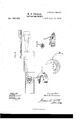
- Figure l represents afront view
- Fig. 2 a back view, (partly in section,) of a waxthread sewingmachine embodying my improvements.
- Fig. 3 is a plan of the lower arm, on which the material to be sewed is placed.
- Figs. 4, 5, 6, and 7 represent, respectively, a
- a cam, A on the main shaft of the machine, works a sliding bar, B, on which is a toothed rack, b, gearing with a pinion, C, the axis cof which projects upward into the middle of the circular shuttle-race, and has on it a shuttle-driver, c', so that at each revolution of the main shaft the shuttle-driver is caused to make a partial rotation-about threequarters of a whole revolution-forward and backward.
- the shuttle D is of the form shown in section at Fig. 6, with a fiat side toward the needle, and the opposite side rounded.
- a portion of the at side d is hinged, so as to form a lid, which is shown opened out in Fig. 4, for the purpose of placing within the shuttle the cop of under thread E, which is readily bent to lie in the curved shuttle. from the interior of the cop is passed down through a hole, and then up again, so as to issue from the upper side of the shuttle at c.
- the spindle of the shuttle-driver is bored up, and a small spindle, F, carrying a button at top, is tted to work vertically therein without revolving.
- the lower end of the spindle is screwed into a square nut, and secured therein by a lock-nut, and this square nut is held in the fork of a lever, G, the end of which rests on the edge of a cam, H.
- a spring, K adjustable by screws, presses down the one -end of the lever G, thereby forcing the button of the spindle F up to the cover of the shuttle-race whenever the hollow h of the cam H presents itself to the end of the lever Gr.
- the needle-thread may be taken from a reel in the ordinary way, having been previously waxed; or it may be waxed as it is used by passing it through a pot, L, containing wax, which pot is placed in ajacket containing oil heated by a gas-flame, M.
- a pot, L containing wax
- M a gas-flame
- segmental shuttle D constructed with an open outer portion, in combination with the dat side d, hinged to the shuttle, and forming a lid to such open side, as and for the purpose described.
Landscapes
- Engineering & Computer Science (AREA)
- Textile Engineering (AREA)
- Sewing Machines And Sewing (AREA)
Description
3 Sheets-Sheet 2.
tened April' 24,1877.
..J nl..
llllll |J www mineras. Puofaumocmpnsn. wAsmNa'roN n c Ulrrrnn Sir WILLIAM F. THOMAS, OF LONDON, ENGLAND.
IMPROVEMENT IN Seme-MACHINES.,
Specication forming part of Letters Patent No. 190,095, dated April 24, 1877; application Vbled January 16, 1877.
- to secure by Letters Patent-that is to say:
This invention relates to an improvement in lock-stitch sewing-machines, particularly'- such as are applied to the stitching of leather, or other purposes for which waxed threads are employed.
I provide a tubular shuttle, bent-to a circular curvature, with a pointed end for entering the loop of the needle-thread; and into this shuttle I insert` the under threadas a cop, which bends to the curvature of the shuttle. l place the shuttle in a circular race formed under the table of the machine, in such a position that the needle descends in a chase at the side of a race. A spindle mounted in the center of the race, and having on it an arm for driving the shuttle, receives a reciprocating rotary motion from a cam, such motion being properly timed, so that the shuttle is caused to enter the loop of the needle-thread. During the passage of the shuttle through the loop the latter has to slip only along the inner periphery of the shuttle, which is short, and
4presents a curvature that renders the slip easy. As the shuttle rotates, its thread is i carried across the central part of the race;
and in order to provide the necessary tension Icause the shuttle-thread to be pressed against the cover of the race by a lever acted on by an adjustable spring, the pressure of the spring being relieved, when required, by the action of a cam.
Figure l represents afront view, and Fig. 2 a back view, (partly in section,) of a waxthread sewingmachine embodying my improvements. Fig. 3 is a plan of the lower arm, on which the material to be sewed is placed. Figs. 4, 5, 6, and 7 represent, respectively, a
plan, a side view, a transverse section, and a perspective view of the shuttle. l
The movements of the needle and feed are effected by cams in the ordinary way. A cam, A, on the main shaft of the machine, works a sliding bar, B, on which is a toothed rack, b, gearing with a pinion, C, the axis cof which projects upward into the middle of the circular shuttle-race, and has on it a shuttle-driver, c', so that at each revolution of the main shaft the shuttle-driver is caused to make a partial rotation-about threequarters of a whole revolution-forward and backward. The shuttle D is of the form shown in section at Fig. 6, with a fiat side toward the needle, and the opposite side rounded. A portion of the at side d is hinged, so as to form a lid, which is shown opened out in Fig. 4, for the purpose of placing within the shuttle the cop of under thread E, which is readily bent to lie in the curved shuttle. from the interior of the cop is passed down through a hole, and then up again, so as to issue from the upper side of the shuttle at c.
The spindle of the shuttle-driver is bored up, and a small spindle, F, carrying a button at top, is tted to work vertically therein without revolving. The lower end of the spindle is screwed into a square nut, and secured therein by a lock-nut, and this square nut is held in the fork of a lever, G, the end of which rests on the edge of a cam, H. A spring, K, adjustable by screws, presses down the one -end of the lever G, thereby forcing the button of the spindle F up to the cover of the shuttle-race whenever the hollow h of the cam H presents itself to the end of the lever Gr. The needle-thread may be taken from a reel in the ordinary way, having been previously waxed; or it may be waxed as it is used by passing it through a pot, L, containing wax, which pot is placed in ajacket containing oil heated by a gas-flame, M. As the thread on its way from thepot L to theneedle is cooled, I prefer to pass it through a tube, N, close to the needle, against which tube, as it oscillates upward and downward with the needle, a
The end of thread taken obvious that it might be arranged to Work on the other side of the needle, and also in a vertical instead of a horizontal plane.
I. am aware that a shuttle for sewing-machines has been constructed of an annular tubular ring having a heel and point, the heel part being adapted t0 be opened for the insertion of a bobbin or a cop, and such I therefore disclaim.
Having thus described the nature of my invention, and in what manner the same is to be performed, I claim- 1. The combination of the sliding spindle F, lever G, spring K, and operating-cam H with thecloth-plate of a sewing-machine, substantially as and for the purpose described.
2. The segmental shuttle D, constructed with an open outer portion, in combination with the dat side d, hinged to the shuttle, and forming a lid to such open side, as and for the purpose described.
Intestimony Whereot' I have signed my name to this specication in the presence of two subscribing Witnesses this 29th day of December, 1876.
W. F. THOMAS.
Witnesses:
CEAS. D. ABEL, OLIVER IMRAY.
Publications (1)
| Publication Number | Publication Date |
|---|---|
| US190098A true US190098A (en) | 1877-04-24 |
Family
ID=2259505
Family Applications (1)
| Application Number | Title | Priority Date | Filing Date |
|---|---|---|---|
| US190098D Expired - Lifetime US190098A (en) | Improvement in sewing-machines |
Country Status (1)
| Country | Link |
|---|---|
| US (1) | US190098A (en) |
Cited By (1)
| Publication number | Priority date | Publication date | Assignee | Title |
|---|---|---|---|---|
| US2682846A (en) * | 1949-04-02 | 1954-07-06 | Irving J Moritt | Sewing machine |
-
0
- US US190098D patent/US190098A/en not_active Expired - Lifetime
Cited By (1)
| Publication number | Priority date | Publication date | Assignee | Title |
|---|---|---|---|---|
| US2682846A (en) * | 1949-04-02 | 1954-07-06 | Irving J Moritt | Sewing machine |
Similar Documents
| Publication | Publication Date | Title |
|---|---|---|
| US190098A (en) | Improvement in sewing-machines | |
| US1105968A (en) | Sewing-machine pull-off. | |
| US300458A (en) | follett | |
| US1020041A (en) | Sewing-machine. | |
| US785168A (en) | Revolving-hook sewing-machine. | |
| US423996A (en) | Sewing-machine for basting | |
| US239998A (en) | Sewing-machine | |
| US73064A (en) | Aibin warth | |
| US730692A (en) | Stitch-forming mechanism for sewing-machines. | |
| US1146406A (en) | Sewing-machine loop-taker. | |
| US246700A (en) | willcox | |
| US272740A (en) | Sewing-machine | |
| US961135A (en) | Sewing-machine. | |
| US1732206A (en) | Needle-thread controller for sewing machines | |
| US339113A (en) | Sewing-machine | |
| US990131A (en) | Sewing-machine. | |
| US660777A (en) | Overseaming sewing-machine. | |
| US905488A (en) | Looper mechanism for sewing-machines. | |
| US55182A (en) | Improvement in sewing-machines | |
| US402432A (en) | Sewing-machine | |
| US39445A (en) | Improvement in sewing-machines | |
| US659482A (en) | Overseaming sewing-machine. | |
| US213537A (en) | Improvement in sewing and darning machines | |
| US274359A (en) | Sewing-machine | |
| US101292A (en) | Improvement in sewing-machine |