US1897880A - Electrical tube - Google Patents
Electrical tube Download PDFInfo
- Publication number
- US1897880A US1897880A US416920A US41692029A US1897880A US 1897880 A US1897880 A US 1897880A US 416920 A US416920 A US 416920A US 41692029 A US41692029 A US 41692029A US 1897880 A US1897880 A US 1897880A
- Authority
- US
- United States
- Prior art keywords
- tube
- grid
- conductors
- inductive
- filament
- Prior art date
- Legal status (The legal status is an assumption and is not a legal conclusion. Google has not performed a legal analysis and makes no representation as to the accuracy of the status listed.)
- Expired - Lifetime
Links
- 239000004020 conductor Substances 0.000 description 33
- 230000001939 inductive effect Effects 0.000 description 23
- 230000010355 oscillation Effects 0.000 description 8
- 238000010276 construction Methods 0.000 description 3
- 239000011521 glass Substances 0.000 description 2
- 230000005291 magnetic effect Effects 0.000 description 2
- 230000015572 biosynthetic process Effects 0.000 description 1
- 230000000903 blocking effect Effects 0.000 description 1
- 238000013016 damping Methods 0.000 description 1
- 230000000694 effects Effects 0.000 description 1
- 230000006698 induction Effects 0.000 description 1
- 238000012986 modification Methods 0.000 description 1
- 230000004048 modification Effects 0.000 description 1
- 230000002265 prevention Effects 0.000 description 1
Images

Classifications
-
- H—ELECTRICITY
- H01—ELECTRIC ELEMENTS
- H01J—ELECTRIC DISCHARGE TUBES OR DISCHARGE LAMPS
- H01J19/00—Details of vacuum tubes of the types covered by group H01J21/00
- H01J19/28—Non-electron-emitting electrodes; Screens
- H01J19/38—Control electrodes, e.g. grid
-
- H—ELECTRICITY
- H01—ELECTRIC ELEMENTS
- H01J—ELECTRIC DISCHARGE TUBES OR DISCHARGE LAMPS
- H01J2893/00—Discharge tubes and lamps
- H01J2893/0001—Electrodes and electrode systems suitable for discharge tubes or lamps
- H01J2893/0012—Constructional arrangements
- H01J2893/0015—Non-sealed electrodes
Definitions
- This invention relates to electrical tubes. It is among the objects of the present invention to provide a novel and improved .vacuum tube particularly adapted to radio work,in which the grid is formed insuch manner as to have an inductive elfect.
- a further object of the invention is to pro vide an inductive grid vacuum'tube adapted foruse in various types of radio circuits, to
- a further object of the invention is to provide a radio tube of improved and novel construction, the arrangement being such that the grid constitutes an induction coil preferably positioned between the plate and filament of the tube.
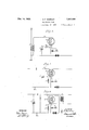
- Figure 1 is a side elevation of a vacuum tube formed in accordance with the present invention, and in which the envelope is partially broken away to show the elements of the tube;
- Fig. 2 is a transverse section taken on the line 22 of Fig. 1;
- Fig. 3 is a sectional view taken on the line 33 of Fig. 2;
- Fig. 4 is a view of a detector circuit utilizing the present tube
- Fig. 5 is a similar view of an amplifying circuit
- Fig. 6 is a view of the tube used as a modulator in an electrical circuit.
- a vacuum tube in which the grid has a substantially inductive characteristic.
- the grid receives its inductive characteristic by its coil formation.
- the experimental operations of the tube indicate that the inductive characteristics of the grid provide a choke for high frequency oscillations, the inductivelyrelatedturns of the coil grid providing a uniform grid potential and acting as a choke for the high'frequencies It will be clearly understood that this theory is tenable on the grounds that the phase rel. tions of the high frequency alternations im-' posed on thegrid will "beat variance in the various turns which have inductive relation, thus tending to offset any such oscillation with respect to its control of the filamentto platedischarge the tube.
- the tube includes a base 10, which supports the conventional enclosing case or envelope 11, which is evacuated in the usual manner, a getter or keeper, or both, being utilized if desired to maintain the proper exhaustion of the tube.
- a getter or keeper Supported from the base 10 and within the tube, the conventional glass or other insulating support 12 is provided.
- a central filament-supporting stem 13 Extending upwardly in the tube from the center 100 of the support 12, a central filament-supporting stem 13 is provided, which extends away from the axis of the tube to clear the plate grid and filament space, its upper end in- 5 cluding an inward extension 1 1 which supports the central uppermost portion of the filament 15.
- the ends of the filament are supported upon stems 16 on either side of the stem 13, conductors 17 being lead therefrom through the support 12 to the tube contacts in the usual manner.
- the tube are completed by the provision of an encircling plate 2 1, whichsurrounds the filament and grid assembly in spaced relation thereto, the plate being supported by end supporting stems 25 of the base 12.
- the filament 15 is energized, the arrangement being such that electrons pass therefrom to the plate 24. In such passing the electrons are affected by the potential of the grid in the usual manner of vacuumtube operation, whereby the tube may be used as detectoramplifier or modulator.
- the electrons emitted from the filament 15 pass between the inductively related coils of the grid filament 21.
- the coil convolution of the grid filament is believed to provide a substantially uniform field of potential which aifects the filament-toplate emission.
- the .,inductive relation of the turns of the grid filament provides for a damping or choking of high frequency potential changes thereof, it being seen that the potential changes in one turn of the grid filament will affect in the usual manner of inductive theory, the potentials of the other turns of the grid filament. Thus high frequency oscillations will be damped and prevented from permitting their influence to reach the output circuit of the tube.
- the magnetic effect of the inductive relation of the coils will also be seen to increase the effect of the grid, whereby its action will provide for increased efiiciency of the tube in all of its various possible uses.
- Fig. 4 discloses a receiving circuit including the resonant circuit within which the secondary of an input transformer T is connected by a conductor 22 with the inductive grid 21 .of the vacuumtube.
- Thegrid is alsoconnected by a conductor 23, with a resistance capacity unit R and variable condenser C, the circuit being completed by the .conne'ction of the-opposite end of the secondary transformer coil with the condenser C.
- the input circuit is also connected with the .filament in the conventional manner, whereby su'bstantial negative biasing for the grid potential is provided.
- su'bstantial negative biasing for the grid potential is provided.
- the tube may also be connected in the circuitfor use as a detector.
- the grid input is indicated by the reference numeral 22, the grid by 21, and the output by the numeral 23.
- the variable condenser C is utilized in the conventional manner, the grid in this case being also biased by the potential of the filament and an external inductance I for the grid circuit is provided.
- this form of the tube is in the manner of the operation of conventional thermionic relay detectors, the external inductance I being arranged to load the return circuit of the grid toprevent ionic loss from the tube.
- the tube is here associated in the circuit to be used as a modulator.
- the grid 21 is provided with an input 22 and the output 23.
- the output includes an external inductance I used in connection with that form of circuit shown in Fig. 5.
- the modulating transformer T is shown in this circuit, whereby modulations may be imposed upon the filament 21 through the connections of the secondary of the transformer T with the input 21 and output 23 of the grid.
- the operation of the tube in this form of the invention is also substantially that of the operation of electrically connecting the the conventional tube, with the exception of the fact that prevention of high frequency oscillation discharge is provided, thisbeing particularly important in connection with currents modulated in the mannerherein shown.
- the improved efficiency ofthe tube probably due to the magnetic relation of the turns of the grid filament in the manner herein discussed, will also be noted in this circuit.
- the invention provides a tube in which higher efliciencies both as to energy transfer and to blocking of high frequency discharge,is pro.- vided.
- the theoretical discussion of the operation of the tube is merelyby way of explanation, and the invention is in no way confined to such explanation. It will be understood that further experimentations with the tube will disclose other factors which result in the improved operation of the tube and thus the theoretical discussion is in no Way confined to the spirit or scope of the appended claims. It will also be understood that the structural presentation of the invention is only by way of illustration and that numerous changes, modifications, and the full use of equivalents may be resorted to without departing from the spirit or scope ofthe appended claims.
- a radio circuit including a vacuum tube having an inductive grid, two conductors ends of the grid with the input of said tube, an external inductance in one of said conductors, a transformer electrically connected with the conductors, the said connection of the transformer with the conductor having the external inductance being between the external inductance and the vacuum tube.
- a circuit including a vacuum tube having an inductive grid, two conductors electrically connecting the grid with the input of said tube, an external inductance in one of said conductors, a modulating transformer electrically connected with the conductors, the said connection with the conductor having the external inductance being between the external inductance and the vacuum tube.
- a radio circuit including a vacuum tube having an inductive grid,'two conductors for electrically connect-ing both ends of said grid with the input of said tube, two condensers electrically associated with one of said conductors, and conducting means around one i of the condensers.
- a radio circuit including a vacuum tube having an inductive grid, conductors connected to both ends of said grid for imparting thereto alternations from an input means, and an inductance in one of said conductors between said input means and the tube.
- a radio circuit including a vacuum tube having an inductive grid, two conductors for electrically connecting both ends of said grid with an input of said tube, two electrical connections between the said two conductors, an impedance .in one of the electrical connections, a condenser in the other electrical con nection, a condenser in one of the conductors between the electrical connections, a ground at the other conductor between the electrical connections, and an inductance in one of the conductors between the electrical connections and the tube.
- a radio circuit including a vacuum tube having an inductive grid, two conductors for 4 electrically connecting both ends of said grid with an input of said tube, a condenser in one conductor, the other conductor being grounded, and an electrical connection havingvan impedance between the two conductors.
- a radio circuit including a vacuum tube having an inductive grid, two conductors for electrically connecting both ends of said grid with an input of said tube, a condenser in one conductor, the other conductor being grounded, and an electrical connection having a condenser between the two conductors.
- a radio circuit including a vacuum tube having an inductive grid, two conductors for electrically connecting both ends of said grid with an input of said tube, a condenser in one conductor, the other conductor being grounded, an electrical connection having a condenser between the two conductors, and an inductance in one of the conductors between the said electrical connections and the tube.
Landscapes
- Amplifiers (AREA)
Description
Feb. 14, 1933. H. F. BARKLEY 1,397,380
' ELECTRICAL TUBE Filed Dec. 27, 1929 2 Sheets-Sheet l UUU INVENTOR Zing-222C imgldj'ifiamfe v I I ATTORNEY H. F. BARKLEY ELECTRICAL TUBE 2 Sheets-Sheet 2 INVENTOR WITNESSES lj'llim'k/e ATTORNEY Patented Feb. 14, 1933 UNITED STATES;
PATENT OFFICE nLncTnIcAn TUBE:
Application filed December 27, 1929. Serial No. 416,920.
' This invention relates to electrical tubes. It is among the objects of the present invention to providea novel and improved .vacuum tube particularly adapted to radio work,in which the grid is formed insuch manner as to have an inductive elfect.
A further object of the invention is to pro vide an inductive grid vacuum'tube adapted foruse in various types of radio circuits, to
be u'sedas a detecto'r,an amplifier, or a modu lator.
A further object of the invention is to provide a radio tube of improved and novel construction, the arrangement being such that the grid constitutes an induction coil preferably positioned between the plate and filament of the tube.
Other objects of the present invention'in-' clude the novel structural combination and interrelation of parts, whereby the whole forms a s imple, improved and eflicient vacuum tube which provides for maximumefiiciency and which will reduce the discharge of high frequency oscillations therefrom.
Other objects of the present invention will be apparent from a consideration of the following specification taken in conjunction with the accompanying drawings, in which Figure 1 is a side elevation of a vacuum tube formed in accordance with the present invention, and in which the envelope is partially broken away to show the elements of the tube;
Fig. 2 is a transverse section taken on the line 22 of Fig. 1;
Fig. 3 is a sectional view taken on the line 33 of Fig. 2;
Fig. 4 is a view of a detector circuit utilizing the present tube; Fig. 5 is a similar view of an amplifying circuit;
Fig. 6 is a view of the tube used as a modulator in an electrical circuit.
In connection with the present invention, there is provided a vacuum tube in which the grid has a substantially inductive characteristic. The grid receives its inductive characteristic by its coil formation. The experimental operations of the tube indicate that the inductive characteristics of the grid provide a choke for high frequency oscillations, the inductivelyrelatedturns of the coil grid providing a uniform grid potential and acting as a choke for the high'frequencies It will be clearly understood that this theory is tenable on the grounds that the phase rel. tions of the high frequency alternations im-' posed on thegrid will "beat variance in the various turns which have inductive relation, thus tending to offset any such oscillation with respect to its control of the filamentto platedischarge the tube. Thisv theory bf operation of the tube is based upon the conventional theory of operation of inductive coils. It will be understood, howeverfthat the invention is not confined to such theory. The experimentalresultsjfrom the use of the tube have been found 'to'show that the tube acts as a'successful obstructor for the output 6- therefrom of high frequency oscillations. In the operation ofthetube, it,has also been' foundthat greater tube eff ciency is realized, andrfrom the theory above propounded, it will be seen that such'efficiency 'would nor- 5-3. mally' result in view ofthe fact that a substantially great grid surface is provided'by' the construction set forth and by virtue of the .fact that the entire grid surface-is of substantially equal potential at all times, the re actions of the inductive relation of the coils providing not only a damper for high frequency oscillations, but also a uniform grid potential throughout the length of the gridand a grid potentially intensified by the inductive characteristics thereof. v
By referring more particularlyto Figs. 1 to 3, inclusive, of the drawings, it will be seen that the preferred embodiment of the present invention is in basic characteristics substantially similar to vacuum tubes now in use. The tube includes a base 10, which supports the conventional enclosing case or envelope 11, which is evacuated in the usual manner, a getter or keeper, or both, being utilized if desired to maintain the proper exhaustion of the tube. Supported from the base 10 and within the tube, the conventional glass or other insulating support 12 is provided. Extending upwardly in the tube from the center 100 of the support 12, a central filament-supporting stem 13 is provided, which extends away from the axis of the tube to clear the plate grid and filament space, its upper end in- 5 cluding an inward extension 1 1 which supports the central uppermost portion of the filament 15. The ends of the filament are supported upon stems 16 on either side of the stem 13, conductors 17 being lead therefrom through the support 12 to the tube contacts in the usual manner. 1
On either side of the stems 16, supports 18 are provided, the upper ends of which "in clude glass or other suitable non-conducting 15 sheaths 19, which are provided with suitable trated in Figs. 4, 5 and 6. The elements of.
the tube are completed by the provision of an encircling plate 2 1, whichsurrounds the filament and grid assembly in spaced relation thereto, the plate being supported by end supporting stems 25 of the base 12.
,In the theoretical operation of the device, the filament 15 is energized, the arrangement being such that electrons pass therefrom to the plate 24. In such passing the electrons are affected by the potential of the grid in the usual manner of vacuumtube operation, whereby the tube may be used as detectoramplifier or modulator. In the construction herein presented, the electrons emitted from the filament 15 pass between the inductively related coils of the grid filament 21. The coil convolution of the grid filament is believed to provide a substantially uniform field of potential which aifects the filament-toplate emission. It is also believed that the .,inductive relation of the turns of the grid filament provides for a damping or choking of high frequency potential changes thereof, it being seen that the potential changes in one turn of the grid filament will affect in the usual manner of inductive theory, the potentials of the other turns of the grid filament. Thus high frequency oscillations will be damped and prevented from permitting their influence to reach the output circuit of the tube. The magnetic effect of the inductive relation of the coils will also be seen to increase the effect of the grid, whereby its action will provide for increased efiiciency of the tube in all of its various possible uses.
Referring more particularly to the diagrammatic illustration of a circuit embodying the present invention, it will be seen that Fig. 4 discloses a receiving circuit including the resonant circuit within which the secondary of an input transformer T is connected by a conductor 22 with the inductive grid 21 .of the vacuumtube. Thegrid is alsoconnected bya conductor 23, with a resistance capacity unit R and variable condenser C, the circuit being completed by the .conne'ction of the-opposite end of the secondary transformer coil with the condenser C.
*The input circuit is also connected with the .filament in the conventional manner, whereby su'bstantial negative biasing for the grid potential is provided. In this .circuit as well as in the circuits illustrated in Figs. 5 and *6,
the grid .is shown connectedas a part-of the input circuit, .both ends being connected in;
the input circuit. The usual biasing of the tube is provided in the customaiymanner, and, if-desired, an external inductive coil is provided, associatedwith the inductive coil of-the grid, as shown in Figs.'5 and 6, By such provision any, anger of electronicloss of the tube is avoided. a v i ,The operation of thecircuit' shownin Fig. 4 is substantially that of the operation of the conventional vacuum tube as an amplifier, the advantages of the preesnt tube being that high frequency oscillations aredamped out in the manner hereinbefore described and improved efliciency of the tube is accomplished.
Referring more particularly to 5 of the drawings, it will be seen that the tube may also be connected in the circuitfor use as a detector. In this circuit the grid input is indicated by the reference numeral 22, the grid by 21, and the output by the numeral 23. The variable condenser C is utilized in the conventional manner, the grid in this case being also biased by the potential of the filament and an external inductance I for the grid circuit is provided.
The operation of this form of the tube is in the manner of the operation of conventional thermionic relay detectors, the external inductance I being arranged to load the return circuit of the grid toprevent ionic loss from the tube.
In connection with Fig. 6, it will be seen that the tube is here associated in the circuit to be used as a modulator. The grid 21 is provided with an input 22 and the output 23. The output includes an external inductance I used in connection with that form of circuit shown in Fig. 5. The modulating transformer T is shown in this circuit, whereby modulations may be imposed upon the filament 21 through the connections of the secondary of the transformer T with the input 21 and output 23 of the grid. The operation of the tube in this form of the invention is also substantially that of the operation of electrically connecting the the conventional tube, with the exception of the fact that prevention of high frequency oscillation discharge is provided, thisbeing particularly important in connection with currents modulated in the mannerherein shown. The improved efficiency ofthe tube probably due to the magnetic relation of the turns of the grid filament in the manner herein discussed, will also be noted in this circuit.
From the foregoing it will be seen that the invention provides a tube in which higher efliciencies both as to energy transfer and to blocking of high frequency discharge,is pro.- vided. The theoretical discussion of the operation of the tube is merelyby way of explanation, and the invention is in no way confined to such explanation. It will be understood that further experimentations with the tube will disclose other factors which result in the improved operation of the tube and thus the theoretical discussion is in no Way confined to the spirit or scope of the appended claims. It will also be understood that the structural presentation of the invention is only by way of illustration and that numerous changes, modifications, and the full use of equivalents may be resorted to without departing from the spirit or scope ofthe appended claims.
I claim:
1. A radio circuit including a vacuum tube having an inductive grid, two conductors ends of the grid with the input of said tube, an external inductance in one of said conductors, a transformer electrically connected with the conductors, the said connection of the transformer with the conductor having the external inductance being between the external inductance and the vacuum tube.
2. A circuit including a vacuum tube having an inductive grid, two conductors electrically connecting the grid with the input of said tube, an external inductance in one of said conductors, a modulating transformer electrically connected with the conductors, the said connection with the conductor having the external inductance being between the external inductance and the vacuum tube.
3. A radio circuit including a vacuum tube having an inductive grid,'two conductors for electrically connect-ing both ends of said grid with the input of said tube, two condensers electrically associated with one of said conductors, and conducting means around one i of the condensers.
4. A radio circuit including a vacuum tube having an inductive grid, conductors connected to both ends of said grid for imparting thereto alternations from an input means, and an inductance in one of said conductors between said input means and the tube.
5. A radio circuit includinga vacuum tube having an inductive grid, two conductors for electrically connecting both ends of said grid with an input of said tube, two electrical connections between the said two conductors, an impedance .in one of the electrical connections, a condenser in the other electrical con nection, a condenser in one of the conductors between the electrical connections, a ground at the other conductor between the electrical connections, and an inductance in one of the conductors between the electrical connections and the tube. I
7. A radio circuit including a vacuum tube having an inductive grid, two conductors for 4 electrically connecting both ends of said grid with an input of said tube, a condenser in one conductor, the other conductor being grounded, and an electrical connection havingvan impedance between the two conductors.
' 8. A radio circuit including a vacuum tube having an inductive grid, two conductors for electrically connecting both ends of said grid with an input of said tube, a condenser in one conductor, the other conductor being grounded, and an electrical connection having a condenser between the two conductors.
9. A radio circuit including a vacuum tube having an inductive grid, two conductors for electrically connecting both ends of said grid with an input of said tube, a condenser in one conductor, the other conductor being grounded, an electrical connection having a condenser between the two conductors, and an inductance in one of the conductors between the said electrical connections and the tube.
HOWARD F. BARKLEY.
Priority Applications (1)
| Application Number | Priority Date | Filing Date | Title |
|---|---|---|---|
| US416920A US1897880A (en) | 1929-12-27 | 1929-12-27 | Electrical tube |
Applications Claiming Priority (1)
| Application Number | Priority Date | Filing Date | Title |
|---|---|---|---|
| US416920A US1897880A (en) | 1929-12-27 | 1929-12-27 | Electrical tube |
Publications (1)
| Publication Number | Publication Date |
|---|---|
| US1897880A true US1897880A (en) | 1933-02-14 |
Family
ID=23651838
Family Applications (1)
| Application Number | Title | Priority Date | Filing Date |
|---|---|---|---|
| US416920A Expired - Lifetime US1897880A (en) | 1929-12-27 | 1929-12-27 | Electrical tube |
Country Status (1)
| Country | Link |
|---|---|
| US (1) | US1897880A (en) |
Cited By (2)
| Publication number | Priority date | Publication date | Assignee | Title |
|---|---|---|---|---|
| US2567415A (en) * | 1948-09-30 | 1951-09-11 | Bell Telephone Labor Inc | Grid assembly and method of fabrication |
| US2761969A (en) * | 1950-01-23 | 1956-09-04 | Bendix Aviat Corp | Frequency modulation detector |
-
1929
- 1929-12-27 US US416920A patent/US1897880A/en not_active Expired - Lifetime
Cited By (2)
| Publication number | Priority date | Publication date | Assignee | Title |
|---|---|---|---|---|
| US2567415A (en) * | 1948-09-30 | 1951-09-11 | Bell Telephone Labor Inc | Grid assembly and method of fabrication |
| US2761969A (en) * | 1950-01-23 | 1956-09-04 | Bendix Aviat Corp | Frequency modulation detector |
Similar Documents
| Publication | Publication Date | Title |
|---|---|---|
| US2200962A (en) | Ultra short wave device | |
| US2312919A (en) | Modulation system for velocity modulation tubes | |
| US2235414A (en) | Thermionic valve circuits | |
| US2399223A (en) | Electron discharge device | |
| US2463229A (en) | Cathode-input signal-translating arrangement | |
| US2333295A (en) | Ultra high frequency electron discharge device | |
| US1897880A (en) | Electrical tube | |
| US2432571A (en) | Electron discharge device employing resonators | |
| US2467736A (en) | Suppression of parasitic oscillations | |
| US2465801A (en) | Ultra high frequency apparatus | |
| US2146016A (en) | Electron discharge device | |
| US2427558A (en) | High-frequency oscillator | |
| US2681997A (en) | Feedback coupling means | |
| US2642533A (en) | Radio-frequency generator | |
| US2451502A (en) | Ultra high frequency oscillator | |
| US2432193A (en) | Microwave oscillator | |
| US2247216A (en) | Resonant line control oscillation generator | |
| US1930499A (en) | Oscillation generator | |
| US2445992A (en) | Electric discharge device for space resonant circuits | |
| US2663799A (en) | Ultrahigh-frequency oscillation generator | |
| US2224649A (en) | Ultra high frequency circuits | |
| US2252458A (en) | Grounded plate amplifier | |
| US2397701A (en) | Frequency control in ultra high frequency circuit | |
| US2646470A (en) | Ultrahigh-frequency tetrode | |
| US2097896A (en) | Amplifying arrangement |