US1896551A - Accounting machine for punching totals - Google Patents
Accounting machine for punching totals Download PDFInfo
- Publication number
- US1896551A US1896551A US209457A US20945727A US1896551A US 1896551 A US1896551 A US 1896551A US 209457 A US209457 A US 209457A US 20945727 A US20945727 A US 20945727A US 1896551 A US1896551 A US 1896551A
- Authority
- US
- United States
- Prior art keywords
- punching
- card
- punch
- column
- punches
- Prior art date
- Legal status (The legal status is an assumption and is not a legal conclusion. Google has not performed a legal analysis and makes no representation as to the accuracy of the status listed.)
- Expired - Lifetime
Links
Images


Classifications
-
- G—PHYSICS
- G06—COMPUTING OR CALCULATING; COUNTING
- G06C—DIGITAL COMPUTERS IN WHICH ALL THE COMPUTATION IS EFFECTED MECHANICALLY
- G06C11/00—Output mechanisms
- G06C11/08—Output mechanisms with punching mechanism
Definitions
- This invention relates to accounting systems wherein data on record ⁇ cards or sheets bearing index points is automatically read, computed, printed, etc. In such systems, it is often found desirable to utilize cards wherein data punched thereon includes items entered into an accumulator of'an accounting device.
- the object of the present invention is to trol the selection of printing elements andpunching elements by the same accumulator to respectively print and punch the data entered into the accumulator.
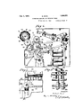
- Fig. 1 is a plan view of the perforating mechanism
- Fig. 2 is a longitudinal sectional view thereof.
- Fig. 3 is a detail of the punching mechanism
- Fig. 4 is a view of an accumulator section of the. accounting mechanism.
- Fig. 5 is a side view of the accumulating wheels and the punch selecting wheels geared thereto
- Fig. 6 is a circuit diagram of the punch selecting mechanism
- Figs. 7 and 8 are details of the column selector.
- FIG. 1. B indicates the card punching structure. The latter is described in detail in the U..S. Patent No. 1,821,078 owned hy the assignee of the present invention.
- the operation of the punching mechanism is as follows: A stack of cards to be punched is placed in magazine 10. The operator draws outa rod 11 which carries one end of the machine, re-operates pull-rod 11 and punches the next card. For each index position on the card, a unch 1.2 is provided, a series of said punches eing placed in a row across the device. Corresponding to each punch is a finger key 13 for manual operation.
- Action of the key serves to depress plunger 14, which by rocking bell crank 15 pivoted thereto at 16, thrusts forward an interposer bar 17 to an advanced position over its corresponding punch 12.
- the forward movement of an interposer rocks an arm 18 in its path, which pulls a link 19 forward and thus closes contacts 20.
- This establishes a circuit to themain punching magnet 21 which attracts its armature 22.
- An arm 24 (Fig. 3)mis fixed to a rock shaft 60 to which is also aliixed a bail 23.
- the free end of arm 24 is connected to armature 22 by an adjustable link 61 so that attraction of the armature causes shaft 60 to rock, thereby lowering bail 23 from a normally raised position shown in Fig. 2 to the lower position shown in Fig. 3.
- Bail 23 is directly over the row of punches 12 and when rocked downwardly depresses any of the interposer bars which have been moved forward, and thereb orces the punch or punches through the card. Punches Whose interposcr bars have not been thrust forward will not be affected, as they will be in the position shown in Fig. 1 with the clearance notch 25 under the bail.
- Contact 26 (Fig. 1) is provided to cut outthe punch selecting magnets 42 while pull-rod 11 is being operated in order to prevent punching operations during that time (as fully explained in aforementioned yPatent No. 1,821,078, page 13,1ine 111 through escapement mechanism operates to feed the next card column under the punches 12. The card being punched rests on top ⁇ plate 62.
- a card carriage comprising a rack 63 has an extending arm 64 at the rear carrying a pivoted member 65 which drops behind the rear edge of the card being fed and ahold-down cam gripper 650 which engages and holds down the forward end of this card.
- the rack 63 has gear teeth on its lower edge meshing with a gear 66 forming part of the casing of a drumenclosing a spiral spring. As the carriage is moved to the right in Fig. 3 the rack rotates gear 66 and tensions the drum spring which thereupon tends to move the carriage back to thel left. ⁇ This movement to the left is controlled by escapement mechanism responsive to the punching operation.
- a bail 70 is mounted on shaft 71 and extends beneath all the interposer bars 17 so that when an interposer is lowered to eHect punching the bail 70 is rocked counterclockwise against the action of abiasing spring (not shown).
- a pawl 73 is loosely mounted on shaft 71 and a spring 72 attached to an extending arm of the pawl tends to force it into engagement with a series of notches formed on the upper edge of rack 63.
- a second pawl 80 pivoted on the machine frame, cooperates with pawl 73 to form an escapement.
- a double arm member 81 is also mounted on shaft 71 and arranged to be operated by bail 70.
- This member is connected to pawl 8O through a pin and slot connection and to pawl 73 by means of a pin 75 engaging an enlarged hole in the pawl. Normally when the bail 70 is in raised position the member 81 holds pawl 80 free of the ratchet teeth and holds pawl 73 in engagement with one of them.
- Fig. 4 (corresponding to Fig. 20 of Patent No. 1,822,594) is shown one of the tabulating counter sections of the Lake tabulator.
- Each counter section includes counterv magnets 27 vfor controlling the movement of counters 28 in accordance with the index points on the'record -card then under the lower one of two sets 0f analyzing brushes.
- the tabulating machine as explained in detail in Patent No. 1,822,594 has an automatic control which changes the operation of the machine in accordance with the groups ⁇ of cards having been tabulated. This control is exercised from a selected group of index points in adjacent card columns. So long as each consecutively fed card has the same group of index points as the preceding card the machine will continue to accumulate the items on the cards and may also list them. When the selected group of index points of a card is not the same as that of the preceding card, the
- the automatic control operates in either of two ways, depending on. the preliminary settingof certain control switches.
- the automatic control vstepped cam 31 which is geared to the counter whee-l and thus always positioned according to the reading on the Wheel. The position of this cam is felt out during totaling by a rockable linger 32.
- an adjustable screw 33 on the end of this finger encounters the uppermost step of the'cam 31 contacts 34 and 35 are closed to energize printing magnets (not shown) to selectthe type for printing which correspond to the reading of the counter wheel.
- the purpose of the present invention is to automatically punch on a record card, the readings, of a certain group of said counters after they have come'to rest.
- each counter wheel 28 (Fig. 4) through an idler .ear is a gear wheel 36 freely rotatable on s aft 37.
- a gear wheel 36 freely rotatable on s aft 37.
- a stationary contact ring 38 Associated with each gear 36 is a stationary contact ring 38, fixed to a stationary shaft 3 and insulated therefrom.
- a commutator ring 39 Encircling each ring 38 and fixed thereto is a commutator ring 39.
- the commutator ring is provided with ten conducting segments 40 insulated from each other and from the contact ring 38.
- a brush 41 fixed t0 gear 36 to rotate therewith, is in constant engagement with ring 38 and is adapted to contact segments 40 successively to conductively connect the segments in turn with the ring 38.
- Each of the segments 40 corresponds to a numeral on the counting wheel 28 and when a particular numeral ou the wheel is at reading position, the segment 40 corresponding to said numeral willY be in Contact with the brush 41.
- Each gear 36, contact ring 38, commutator ring 39 and brush 41 constitute a punch selecting unit.
- selecting units There are as many such selecting units as the number of counting Wheels but for the purposes of illustration, only three are shown in Fig. 6, the one characterized by an a after its reference numerals being controlled from the units counter 28a of a group of adjacent denominational order column counters, the selector unit with b after the reference characters corresponding to the tens counting Wheel of said group, and the one with c corresponding to the hundreds counter of the group.
- each of the commutator segments 40 In series with each of the commutator segments 40 is a magnet 42 corresponding to and adapted for actuating one o the interposers 17.
- the magnets are connected at one end by a common lead 43 to similar segments on each of the commutator units. Since only one column at a time is punched, only ten selecting magnets are provided for cooperation with all of the tabulating counters.
- Each magnet corresponds to the numeral characterizin the commutator segments with which 1t is in series and operates the punch for perforating the card to designate said numeral.
- T his commutator comprises a frame bar 47 fixed to the punch frame 470 in anv suitable manner, as for example, by an end bracket 471 and a bottom angle bracket 472 (see particularly Fig. 8). Mounted on top of frame bar 47 and insulated therefrom is a rear contact rail 45 and insulated from the latter is a row of contact sections 46 insulated from each other and carried by the bar 47.
- the magnets 42 are in series with one side of a source of current 44, the other side of which connects to the contact rail 45.
- the center lines of sections 46 are a card column apart and the number of sections equals the number of columns on a card.
- Rigidly connected with the card holding carriage of the punching mechanism by means of a bracket 473 i secured to rack 63 and a plate 474 is a contact piece 48 (Figs. 1, 7 and 8) for conductively connecting contact rail 45 and the sections 46.
- the contact piece 48 As the carriage, after a punching operation, moves a distance of one card column, the contact piece 48 also moves the same distance and thus connects each of the sections 46 in succession to the rail 45.
- Each of the contact rings 38 of the selectors is removably plugged to one of the contact sections 46.
- the units counter ring 38 is connected to rail 45 through normally open contacts 50, the lead 51a from the ring belng removably connected to one side of contacts 50.
- the ring 381) of the commutator for the tens counter 1s removably connected by lead 51b to the section 461) corresponding to the card column in which the data on said tens counter is to ybe punched.
- the ring 38e is removably connected by lead 510 to the section 46c corresponding to the card column in which the data on the hundreds counter is to be punched.
- the tens counter 286 will be associated through the rin 38b with section 46b corresponding to t e twenty-first column and the hundreds counter will be associated through ring 38e with section 46c corresponding to the twenty-second card column.
- the removable connections of the rings 38 to column sections 46 permits selective association of any of the counting wheels with any of the column sections.
- the mode of operation of the parts described is as follows: The operator manually ⁇ actuates keys 13 to perforate data in the card columns preceding those which are to be perforated automatically in accordance with the reading on the counters of said tabulating machine. Inthis preliminary manual operation of thepunchin'g machine, if any 'column is not to contain any of items lto 9, the 0 key may be depressed to cause the 0 osition of the column to be perforated. I it is not desired to thus perforate columns in their zero position, the operator depresses the skip key (see Fig. 1 as is well understood in the art. This s ip key shown in Fig.
- the punching of the card in this column in accordance with the reading of the units counter is placed under control of the punch operator in order thatupon the completion of a manual punching, the automatic punching may not follow directly without the knowledge of the operator. For this reason, the units sliding ring 38a is not connected to section 46a but to the common contact rail 45 through the normally open contacts 50 as hitherto explained.
- a device for automatically operating a punching machine provided with punches and card feed mechanism to perforate a record card in accordance with the reading of the accumulating mechanism of an accounting machine, comprising punch selecting means, and means for operating the same in synchronism with the operation of the accumulating mechanism and means controlled by the card feed mechanism of the punching machine in accordance with the position of the card relative to the punches and associated with the first mentioned means to control an automatic operation of the punchesto perforate the card in accordance with said reading.
- a device for automatically operating a punching machine having a card feeding carriage to perforate a record card in accordance with the reading of accumulating mechanism comprising means controlled by the position of said carriage to determine the card columns in which the reading is to be punched and means controlled by the accumulating mechanism to ldetermine the position of the perforations in the columns.
- a device for automatically operating a punching mechanism including punches to perforate a record card in accordance with the reading of accumulating means, comprising means controlled by said accumulating means for selecting the punches to be automatically operated and means controlled by the punching mechanism for selecting the columns to be perforated.
- a device for automatically operating a punching mechanism including punches to perforate a plurality of adjacent columns in accordance with the reading of accumulating elements, comprising means operated in accordance with the reading of said accumulating elements for selecting the punches for operation, means operated by the punching mechanism to select the card columns to be perforated, and means for placing the perpunching means to punch parallel columns of a record card, means for selectively operating the punches, and means for selectively interchangeably, and readily releasably connecting any of said accumulating elements to said punch operatin means to cause punching of any desired co umn of the record under control of any one of said accumulating elements in accordance with the data entered into said accumulatinv element.
- punches for perforating a record sheet electrical operating and selecting means for the punches, item receiving members, electrical connections between the item receiving members and the punch operating and selecting means, a manually controlled switch for rendering the connections of one item receiving member effective to cause the punch operating and selecting means to operate the punches in accordance with the item carried by the last-named item receiving member, and switches in the connections between the other item receiving members and the punch selecting and operat ing means automatically operated to cause operation of the punch selecting and operating means in accordance with the item carried by the last-named item receiving members.
Landscapes
- Engineering & Computer Science (AREA)
- Physics & Mathematics (AREA)
- Computer Hardware Design (AREA)
- Computing Systems (AREA)
- General Physics & Mathematics (AREA)
- Theoretical Computer Science (AREA)
- Perforating, Stamping-Out Or Severing By Means Other Than Cutting (AREA)
Applications Claiming Priority (1)
| Application Number | Priority Date | Filing Date | Title |
|---|---|---|---|
| DE280955T | 1926-11-20 |
Publications (1)
| Publication Number | Publication Date |
|---|---|
| US1896551A true US1896551A (en) | 1933-02-07 |
Family
ID=31893808
Family Applications (1)
| Application Number | Title | Priority Date | Filing Date |
|---|---|---|---|
| US209457A Expired - Lifetime US1896551A (en) | 1926-11-20 | 1927-07-30 | Accounting machine for punching totals |
Country Status (2)
| Country | Link |
|---|---|
| US (1) | US1896551A (enExample) |
| GB (1) | GB280955A (enExample) |
Cited By (2)
| Publication number | Priority date | Publication date | Assignee | Title |
|---|---|---|---|---|
| US2615623A (en) * | 1952-10-28 | Automatic old balance pickup means | ||
| US3101894A (en) * | 1960-12-15 | 1963-08-27 | Ncr Co | Data recording system with zero suppression |
-
1927
- 1927-07-30 US US209457A patent/US1896551A/en not_active Expired - Lifetime
- 1927-11-19 GB GB31137/27A patent/GB280955A/en not_active Expired
Cited By (2)
| Publication number | Priority date | Publication date | Assignee | Title |
|---|---|---|---|---|
| US2615623A (en) * | 1952-10-28 | Automatic old balance pickup means | ||
| US3101894A (en) * | 1960-12-15 | 1963-08-27 | Ncr Co | Data recording system with zero suppression |
Also Published As
| Publication number | Publication date |
|---|---|
| GB280955A (enExample) | 1929-02-19 |
Similar Documents
| Publication | Publication Date | Title |
|---|---|---|
| US1834561A (en) | Accounting machine and punching mechanism controlled thereby | |
| US2255011A (en) | Recording machine | |
| US1976600A (en) | Card punching machine | |
| US2007391A (en) | Record controlled punch | |
| US1962750A (en) | Card reproducing machine | |
| US1896551A (en) | Accounting machine for punching totals | |
| US2016705A (en) | Automatic card punch | |
| GB445846A (en) | Improvements in or relating to code translating apparatus | |
| US2690222A (en) | Mark sensing reproducer | |
| US2343414A (en) | Punching machine | |
| GB745482A (en) | Key-controlled perforating machines | |
| US1946913A (en) | Automatic punching machine | |
| US2391773A (en) | Record controlled tape punching machine | |
| US2421069A (en) | Punch | |
| US2475315A (en) | Record verifying machine | |
| US2765116A (en) | Data storing apparatus for business machines, particularly accounting machines or the like | |
| US2044708A (en) | Card punching machine | |
| US2172062A (en) | Tabulating machine | |
| US1866995A (en) | Tabulating machine | |
| US2013530A (en) | Time recording punch | |
| US2078084A (en) | Card verifier | |
| US3278897A (en) | Method and apparatus for error correction of information recorded in a combined printing and recording machine | |
| US1834562A (en) | Accounting machine with punching attachment | |
| US1976599A (en) | Printing device | |
| US2983440A (en) | wales |