US1892439A - Semifloating electric contact - Google Patents
Semifloating electric contact Download PDFInfo
- Publication number
- US1892439A US1892439A US499505A US49950530A US1892439A US 1892439 A US1892439 A US 1892439A US 499505 A US499505 A US 499505A US 49950530 A US49950530 A US 49950530A US 1892439 A US1892439 A US 1892439A
- Authority
- US
- United States
- Prior art keywords
- shoes
- spring arms
- contact
- support
- secured
- Prior art date
- Legal status (The legal status is an assumption and is not a legal conclusion. Google has not performed a legal analysis and makes no representation as to the accuracy of the status listed.)
- Expired - Lifetime
Links
- 239000004020 conductor Substances 0.000 description 6
- 238000010276 construction Methods 0.000 description 4
- 238000004519 manufacturing process Methods 0.000 description 2
- 230000000694 effects Effects 0.000 description 1
- 239000012212 insulator Substances 0.000 description 1
- 239000000463 material Substances 0.000 description 1
- 230000004048 modification Effects 0.000 description 1
- 238000012986 modification Methods 0.000 description 1
- 230000002093 peripheral effect Effects 0.000 description 1
- 239000007787 solid Substances 0.000 description 1
Images


Classifications
-
- H—ELECTRICITY
- H01—ELECTRIC ELEMENTS
- H01H—ELECTRIC SWITCHES; RELAYS; SELECTORS; EMERGENCY PROTECTIVE DEVICES
- H01H1/00—Contacts
- H01H1/12—Contacts characterised by the manner in which co-operating contacts engage
- H01H1/36—Contacts characterised by the manner in which co-operating contacts engage by sliding
- H01H1/46—Contacts characterised by the manner in which co-operating contacts engage by sliding self-aligning contacts
Definitions
- This invention relates to a semi-floating electric contact particularly adapted for line switches, panel switches and the like.
- the object of the present invention is to generally improve and simplify the construction and operation of switches of the character described and in particular to provide a contact or shoe mounting which will automatically maintain uniform pressure and engagement between the switch blade and shoes regardless of wear and disalignment between the blade and shoes.
- Fig. 1 is a plan view of the spring arm whereby one of the shoes is supported
- Fig. 2 is a side elevation showing a pair of spring arms and shoes supported thereby, said View also showing a stationary support and a conductor whereby current is carried from the support to the shoes,
- Fig. 3 is an end view of Fig. 2,
- Fig. 4 is an end view of a switch blade
- Fig. 5 is a side elevation showing a modi' fied form of the shoe support
- Fig. 6 is a plan view of the same
- Fig. 7 is an end view
- Fig. 8 shows the switch as constructed and mounted when employed as a line switch
- Fig. 9 is a cross section taken on line IX-IX of Fig. 8,
- Fig. 10 is .a cross section taken on line XX of Fig. 8,
- Fig. 11 is a front View of a panel switch
- Fig. 12 is a vertical section taken on line XIIXII of Fig. 11.
- This problem has been substantially elim- 7 inated in the present instance by providing a semi-floating support for the contact shoes which is sufliciently flexible to take care of normal wear and slight disalignments between the shoes and the switch blade. Also a semi-floating spring actuating support has at the same time been provided which insures a maximum and uniform pressure between the shoes and the blade.
- FIGs. 1 to 4 One form of the semi-floating support is disclosed in Figs. 1 to 4, in which A indicates a pair of contact shoes which are carried by a stationary support B of any suitable construction, and O a switch blade mounted to be swung into and out ofengagement with relation to the shoes.
- the support for the shoes A comprises a pair of spring arms, such as shown at 2, these arms being yieldable first of all longitudinally, and secondly, tortionally as their center portions are cut away as indicated at 2a.
- the inner ends of the spring arms are secured to the support B by means of screws 3 while the outer ends carry spacing blocks 4 and the shoes A, these shoes and blocks being secured by means of screws 5.
- a contact shoe support constructed in this manner is semi-floating and flexible both longitudinally and tortionally hence permitting the shoes to spread outwardly or away from each other as the switch blade enters, and it also permits the shoes to yield suificiently in all directions to take care of any slight disalignment.
- Uniform pressure throughout the entire contact area is obtained due to the fact that the spring pressure is applied centrally of the contact shoes as indicated by the dotted lines 66. That is, when outward pressure is exerted on the shoes during the entrance of the switch blade the spring arms yield and flex during flexing assume the shape of an ogee.
- An ogee curve has a point of contraflexure and the spring arms are, in this instance, designed so that the point of contraflexure is formed on the center line indicated at 6-6.
- the spring arms 2 are secured to the shoes A along a line parallel thereto and at a distance a from the center line 66. Also spring arms 2 are fixed to stationary support B along a line parallel to the shoes and at a distance a from the center line 6-6.. lVith this arrangement of shoes A, spring arms 2, and the stationary support B, when shoes A are moved in a direction away from each other due to the entrance of the switch blade C, spring arms 2 will be deflected in such a mannor as to produce a point of contraflexure on the center line 66.
- the spring pressure acting on the shoes A will therefore have the effect of a single force acting on the center line 6-6 directly over the center points of the shoes and thus tend to cause the shoes A to exert a uniform pressure throughout their length on the switch blade C.
- switch blade C is not exactly parallel to the free position of the shoes the point of contraflexure will be shifted from the center line 6 6 .by an amount depending upon the degree of misalignment between the shoes and blade, but within reasonable tolerance in manufacture the misalignment will not be suflicient to cause more than a small ceparture from uniformity in pressure along the length of the shoes.
- a line switch structure is shown in Figs. 8 to 10, inclusive.
- 20 indicates an insulator which forms a break in the line conductor 21 and D indicates a switch blade whereby the circuit through the line is made or broken.
- the brackets 22 and clamps 23 illustrated are of the usual construction.
- the switch blade is, in this instance, pivoted as at 24 between a pair of plates 25 secured to one of the brackets while the opposite end of the switch blade is movable into and out of engagement with relation to a pair of contact shoes 26 secured to the opposite bracket.
- the shoes and their supporting arms differ from the other structures so far described to the extent that they are made as an'integral unit; the spring arms being indicated at 27 and the integral shoes at 26.
- Their operation is identical to the other structures as sufficient flexibility is obtained to take care of any disalignment and uniform pressure is maintained as a point of contraflexure is obtained at a point centrally of the shoes.
- a device of the character described comprising a support, a pair of interspaced spring arms secured at their inner ends to said support and extending outwardly therefrom, said arms having contact shoes secured to their outer ends and the shoes lying between the arms and being substantially parallel to each other and to the arms, said spring arms being flexible both longitudinally and tortionally and adapted to exert an inward pressure on the shoes at a point substantially centrally of their length and width.
- a device of the character described comprising a. support, a pair of interspaced spring arms secured at their inner ends to said support and extending outwardly therefrom, spacing blocks secured to the outer ends of the spring arms, and a pair of elongated contact shoes secured at their outer ends to the spacing blocks their inner ends termi nating at a point adjacent the inner ends of the spring arms, said spring arms being flexible both longitudinally and tortionally to permit movement of the shoes away from each other during entrance of the switch blade and also to permit lateral rocking movement where there is disalignment between the shoes and blade.
- a device of the character described co1n prising a support, a pair of interspaced spring arms secured at their inner ends to said support and extending outwardly therefrom, spacing blocks secured to the outer ends of the spring arms, and a pair of elongated contact shoes secured at their outer ends to the spacing blocks, their inner ends terminating at a point adjacent the inner ends of the spring arms, said spring arms adapted to exert pressure on the contact shoes at a point substantially centrally of their length.
- a device of the character described com prising a support, a pair of interspaced spring arms secured at their inner ends to said support and extending outwardly therefrom, spacing blocks secured to the outer ends of both longitudinally and laterally to permit movement of the shoes away from each other during entrance of the switch blade and also to permit lateral rocking movement in all directions where there is disalignment between the shoes and blade, and flexible current conductors connecting the support and shoes.
- a device of the character described comprising a pair of interspaced contact shoes having substantially flat surfaces disposed opposite to each other, a blade adapted to enter between the flat surfaces of said shoes and having fiat sides for contact therewith, and resilient means supporting the shoes and exerting inward pressure thereon at a point substantially centrally of the length and width of the shoes to insure uniform contact between the flat surfaces of the shoes and the blade.
- a device of the character described comprising a supporting block having a central recess formed therein, a pair of spring arms secured to said supporting block at opposite sides of said recess, and a contact shoe supported by the outer end of each of said spring arms and extending inwardly to a a point within said recess.
- a device of the character described comprising a support, spring arms extending outwardly from said support, and contact shoes fixed with relation to the outer ends of said spring arms and extending toward said support to a point beyond the point of con tact between the spring arms and said support.
- a support a spring arm extending outwardly therefrom, and a contact shoe supported by the spring arm and extending toward said support, said contact shoe being at least as long as the free portion of said spring arm.
- the spring arms and a pair of elongated contact shoes secured at their outer ends to the spacing blocks, their inner ends terminating at a point adjacent the inner ends of the spring arms, said spring arms adapted to exert pressure 011 the contact shoes at a point substantially centrally of their length and width.
- a device of the character described comprising a support, a pair of interspaced spring arms secured at their inner ends to said support and extending outwardly thererom, spacing blocks secured to the outer ends of the spring arms, a pair of elongated contact shoes secured at their outer ends to the spacing blocks, their inner ends terminating at a point adjacent the inner ends of the spring arms, said spring arms being flexible
Landscapes
- Footwear And Its Accessory, Manufacturing Method And Apparatuses (AREA)
Description
Dec. 27, 1932. J, s n- SEMIFLOATING ELECTRIC CONTACT 5 Sheets-Sheet 1 Filed Dec. 2, 1930 7 INVENTOR. 47W W1 A TTORNEYS.
Dc. 27, 1932. s n-H 1,892,439
SEMIFLOATING ELECTRIC CONTACT Filed Dec. 2, 1950 5 Sheets-Sheet 2 IN VEN TOR.
A TTORNEYS.
27, 9 J. u. SMiTH SEMIFLOATING ELECTRIC CONTACT Filed Dec. 2, 1950 5 Sheets-Sheet 5 y Y gVLI IENTOR I y ,WY
TTORNEYS.
Dec. 27,1932. sMn-H SEMIFLOAFING ELECTRIC CONTACT Filed Dec. 2. 1950 s Sheets-Shed 4 INVENTOR.
y BY 4,4? MM ATTORNEYS:
Dec. 27, 1932. J, u s n- I 1,892,439
SEMIFLOATING ELECTRIC CONTACT Filed Dec. 2, 1930 5 Sheets-Sheet 5 INVEN 0R.
zyw y W A TTORNEYS.
Patented Dec. 27, 1932 JAMES U. SMITH, OF BERKELEY, CALIFORNIA SEMIFLOATING ELECTRIC CONTACT Application filed December 2, 1930. Serial No. 499,505.-
This invention relates to a semi-floating electric contact particularly adapted for line switches, panel switches and the like.
The necessity of pressure and uniform engagement between the switch blade and the contacts or shoes in an electric switch should be apparent when it is known that current carrying capacity is proportional to contact area and the pressure maintained and also that burning and pitting is liable to take place where the switch blade and contacts are poorly engaged.
In the construction and operation of certain types of electric switches such as line switches, panel switches, and the like, considerable trouble is encountered in obtaining and maintaining a uniform contact and pressure between the switch blade and the contacts, or vice versa. In fact, the labor cost in manufacturing such switches is quite high due to the large proportion of time consumed in fitting and grinding the blade and contacts.
The object of the present invention is to generally improve and simplify the construction and operation of switches of the character described and in particular to provide a contact or shoe mounting which will automatically maintain uniform pressure and engagement between the switch blade and shoes regardless of wear and disalignment between the blade and shoes. I
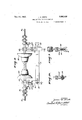
The invention is shown by way of illustration in the accompanying drawings, in which Fig. 1 is a plan view of the spring arm whereby one of the shoes is supported,
Fig. 2 is a side elevation showing a pair of spring arms and shoes supported thereby, said View also showing a stationary support and a conductor whereby current is carried from the support to the shoes,
Fig. 3 is an end view of Fig. 2,
Fig. 4 is an end view of a switch blade,
Fig. 5 is a side elevation showing a modi' fied form of the shoe support,
Fig. 6 is a plan view of the same,
Fig. 7 is an end view,
Fig. 8 shows the switch as constructed and mounted when employed as a line switch,
Fig. 9 is a cross section taken on line IX-IX of Fig. 8,
Fig. 10 is .a cross section taken on line XX of Fig. 8,
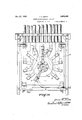
Fig. 11 is a front View of a panel switch,
Fig. 12 is a vertical section taken on line XIIXII of Fig. 11.
In lineswitches considerable trouble is encountered in maintaining proper alignment and engagemet between the switch blade and the contact shoes as the switch structure and its attachment to the power line cannot be as rigid as might be desired and, while this con dition does not exist in the same degree in panel and other types of electric switches where the mounting is more solid and rigid, considerable trouble and expense is nevertheless encountered in maintaining the desired alignment, pressure and contact.
This problem has been substantially elim- 7 inated in the present instance by providing a semi-floating support for the contact shoes which is sufliciently flexible to take care of normal wear and slight disalignments between the shoes and the switch blade. Also a semi-floating spring actuating support has at the same time been provided which insures a maximum and uniform pressure between the shoes and the blade.
One form of the semi-floating support is disclosed in Figs. 1 to 4, in which A indicates a pair of contact shoes which are carried by a stationary support B of any suitable construction, and O a switch blade mounted to be swung into and out ofengagement with relation to the shoes. The support for the shoes A comprises a pair of spring arms, such as shown at 2, these arms being yieldable first of all longitudinally, and secondly, tortionally as their center portions are cut away as indicated at 2a. The inner ends of the spring arms are secured to the support B by means of screws 3 while the outer ends carry spacing blocks 4 and the shoes A, these shoes and blocks being secured by means of screws 5.
A contact shoe support constructed in this manner is semi-floating and flexible both longitudinally and tortionally hence permitting the shoes to spread outwardly or away from each other as the switch blade enters, and it also permits the shoes to yield suificiently in all directions to take care of any slight disalignment. Uniform pressure throughout the entire contact area is obtained due to the fact that the spring pressure is applied centrally of the contact shoes as indicated by the dotted lines 66. That is, when outward pressure is exerted on the shoes during the entrance of the switch blade the spring arms yield and flex during flexing assume the shape of an ogee. An ogee curve has a point of contraflexure and the spring arms are, in this instance, designed so that the point of contraflexure is formed on the center line indicated at 6-6. The spring arms 2 are secured to the shoes A along a line parallel thereto and at a distance a from the center line 66. Also spring arms 2 are fixed to stationary support B along a line parallel to the shoes and at a distance a from the center line 6-6.. lVith this arrangement of shoes A, spring arms 2, and the stationary support B, when shoes A are moved in a direction away from each other due to the entrance of the switch blade C, spring arms 2 will be deflected in such a mannor as to produce a point of contraflexure on the center line 66. The forces, or'in other words, the spring pressure acting on the shoes A will therefore have the effect of a single force acting on the center line 6-6 directly over the center points of the shoes and thus tend to cause the shoes A to exert a uniform pressure throughout their length on the switch blade C. On the other hand, if switch blade C is not exactly parallel to the free position of the shoes the point of contraflexure will be shifted from the center line 6 6 .by an amount depending upon the degree of misalignment between the shoes and blade, but within reasonable tolerance in manufacture the misalignment will not be suflicient to cause more than a small ceparture from uniformity in pressure along the length of the shoes. The transverse center line which coincides with the line 66 and the center line in the other direction falls on that of the spring, this permits limited rotation of the shoes on the line 66 to take care of misalignment of the blade C in that direction. Therefore, blade C may be moved relative to the shoes A, or vice versa, in the plane of the shoes so as to bring the blade from a position of engagement to a position clear of the shoes as in the action of an electric switch and back again as often as desired with an exact repetition of the contact conditions at the end of each cycle of operation.
In actual operation current may be carried to the shoes A through flexible conductors such as shown at 7. but in the modification shown in Figs. 5, 6, and 7 the spring arms indicated at 8 may themselves be conductors. The modified structure shown is susbtantially. identical to that described, the only difference being that the spring arms function as current conductors and also that they are bent as shown at 9 in Fig. 5. The spring arms thus bent function in a manner identical to the fiat spring arms shown in Fig. 2 and as such will automatically maintain and apply a central pressure on the contact shoes; lateral flexibility being obtained by splitting the spring arms 8 longitudinally as indicated at 10. Figs. 11 and 12 disclose the manner in which he semi-floating contacts are applied to apanel switch. These drawings also disclose the fact that the semi-floating contacts may be movable or stationary, for instance, by referring to the reference character 11 it will be noted that this indicates a stationary bracket secured to the panel 12 of the switch. This bracket carries contact shoes 13. These in turn engage the disc 14 of the switch, the disc functioning as the movable blade of the switch. By referring to the reference character 15, it will be noted that this shows a bracket which is secured to the peripheral edge of the disc and that this carries a pair of contact shoes 16, these shoes moving into and out of engagement with a series of stationary cont-actblades as shown at 17, hence it discloses the fact that the semi-floating contact shoes may be stationary or movable as clearly illustrated.
A line switch structure is shown in Figs. 8 to 10, inclusive. In these drawings 20 indicates an insulator which forms a break in the line conductor 21 and D indicates a switch blade whereby the circuit through the line is made or broken. The brackets 22 and clamps 23 illustrated are of the usual construction. The switch blade is, in this instance, pivoted as at 24 between a pair of plates 25 secured to one of the brackets while the opposite end of the switch blade is movable into and out of engagement with relation to a pair of contact shoes 26 secured to the opposite bracket. The shoes and their supporting arms differ from the other structures so far described to the extent that they are made as an'integral unit; the spring arms being indicated at 27 and the integral shoes at 26. Their operation, however, is identical to the other structures as sufficient flexibility is obtained to take care of any disalignment and uniform pressure is maintained as a point of contraflexure is obtained at a point centrally of the shoes.
lVhile certain features of the present invention are more or less specifically'described, I wish it understood that various changes may be resorted to within the scope of the appended claims. Similarly, that the materials and finish of the several parts employed may be such as the manufacturer may decide, or varying conditions or uses may demand.
Having thus described my invention, what I claim and desire to secure by Letters Patent is 1. A device of the character described comprising a support, a pair of interspaced spring arms secured at their inner ends to said support and extending outwardly therefrom, said arms having contact shoes secured to their outer ends and the shoes lying between the arms and being substantially parallel to each other and to the arms, said spring arms being flexible both longitudinally and tortionally and adapted to exert an inward pressure on the shoes at a point substantially centrally of their length and width.
2. A device of the character described comprising a. support, a pair of interspaced spring arms secured at their inner ends to said support and extending outwardly therefrom, spacing blocks secured to the outer ends of the spring arms, and a pair of elongated contact shoes secured at their outer ends to the spacing blocks their inner ends termi nating at a point adjacent the inner ends of the spring arms, said spring arms being flexible both longitudinally and tortionally to permit movement of the shoes away from each other during entrance of the switch blade and also to permit lateral rocking movement where there is disalignment between the shoes and blade.
3. A device of the character described co1nprising a support, a pair of interspaced spring arms secured at their inner ends to said support and extending outwardly therefrom, spacing blocks secured to the outer ends of the spring arms, and a pair of elongated contact shoes secured at their outer ends to the spacing blocks, their inner ends terminating at a point adjacent the inner ends of the spring arms, said spring arms adapted to exert pressure on the contact shoes at a point substantially centrally of their length.
4. A device of the character described com prising a support, a pair of interspaced spring arms secured at their inner ends to said support and extending outwardly therefrom, spacing blocks secured to the outer ends of both longitudinally and laterally to permit movement of the shoes away from each other during entrance of the switch blade and also to permit lateral rocking movement in all directions where there is disalignment between the shoes and blade, and flexible current conductors connecting the support and shoes.
6. In a device of the character described comprising a pair of interspaced contact shoes having substantially flat surfaces disposed opposite to each other, a blade adapted to enter between the flat surfaces of said shoes and having fiat sides for contact therewith, and resilient means supporting the shoes and exerting inward pressure thereon at a point substantially centrally of the length and width of the shoes to insure uniform contact between the flat surfaces of the shoes and the blade.
7 A device of the character described, comprising a supporting block having a central recess formed therein, a pair of spring arms secured to said supporting block at opposite sides of said recess, and a contact shoe supported by the outer end of each of said spring arms and extending inwardly to a a point within said recess.
8. A device of the character described, comprising a support, spring arms extending outwardly from said support, and contact shoes fixed with relation to the outer ends of said spring arms and extending toward said support to a point beyond the point of con tact between the spring arms and said support.
9. In a device of the character described, a support, a spring arm extending outwardly therefrom, and a contact shoe supported by the spring arm and extending toward said support, said contact shoe being at least as long as the free portion of said spring arm.
JAMES U. SMITH.
the spring arms, and a pair of elongated contact shoes secured at their outer ends to the spacing blocks, their inner ends terminating at a point adjacent the inner ends of the spring arms, said spring arms adapted to exert pressure 011 the contact shoes at a point substantially centrally of their length and width.
5. A device of the character described comprising a support, a pair of interspaced spring arms secured at their inner ends to said support and extending outwardly thererom, spacing blocks secured to the outer ends of the spring arms, a pair of elongated contact shoes secured at their outer ends to the spacing blocks, their inner ends terminating at a point adjacent the inner ends of the spring arms, said spring arms being flexible
Priority Applications (1)
| Application Number | Priority Date | Filing Date | Title |
|---|---|---|---|
| US499505A US1892439A (en) | 1930-12-02 | 1930-12-02 | Semifloating electric contact |
Applications Claiming Priority (1)
| Application Number | Priority Date | Filing Date | Title |
|---|---|---|---|
| US499505A US1892439A (en) | 1930-12-02 | 1930-12-02 | Semifloating electric contact |
Publications (1)
| Publication Number | Publication Date |
|---|---|
| US1892439A true US1892439A (en) | 1932-12-27 |
Family
ID=23985516
Family Applications (1)
| Application Number | Title | Priority Date | Filing Date |
|---|---|---|---|
| US499505A Expired - Lifetime US1892439A (en) | 1930-12-02 | 1930-12-02 | Semifloating electric contact |
Country Status (1)
| Country | Link |
|---|---|
| US (1) | US1892439A (en) |
-
1930
- 1930-12-02 US US499505A patent/US1892439A/en not_active Expired - Lifetime
Similar Documents
| Publication | Publication Date | Title |
|---|---|---|
| US1477527A (en) | Contact spring | |
| ATE82435T1 (en) | CONTACT ELEMENT FOR ELECTRICAL PLUG-IN CONNECTOR. | |
| ES413455A1 (en) | A SET OF CONTACT SPRINGS. | |
| US2348088A (en) | Detachable relay | |
| US1892439A (en) | Semifloating electric contact | |
| US2587458A (en) | Contact spring | |
| GB720899A (en) | ||
| US2414778A (en) | Snap-action switch | |
| US2861168A (en) | Electric heater panel contact structure | |
| US2525408A (en) | Electrical contact for switching devices | |
| US2063338A (en) | Burnishing tool | |
| US3012117A (en) | Mounting for the fixed contacts and the terminals of an electromagnetic relay | |
| US1908694A (en) | Variable condenser | |
| US2408873A (en) | Snap acting thermostatic switch | |
| US1158708A (en) | Electric-circuit connector. | |
| US2542669A (en) | Adjustable terminal supporting interconnector | |
| US2548986A (en) | Sectionalized bus bar construction | |
| US2577742A (en) | Selector switch brush unit assembly | |
| US2200053A (en) | Counting chamber | |
| US1586682A (en) | Switch contact member | |
| US1507493A (en) | Circuit controller for semaphore signal mechanisms | |
| US1506744A (en) | Floating contact terminal | |
| US1747320A (en) | Electrical switch | |
| US1742231A (en) | Condenser | |
| US1858598A (en) | Rotary snap switch |