US1891908A - Means for and method of handling candy goods - Google Patents
Means for and method of handling candy goods Download PDFInfo
- Publication number
- US1891908A US1891908A US420250A US42025030A US1891908A US 1891908 A US1891908 A US 1891908A US 420250 A US420250 A US 420250A US 42025030 A US42025030 A US 42025030A US 1891908 A US1891908 A US 1891908A
- Authority
- US
- United States
- Prior art keywords
- conveyor
- candy
- goods
- drum
- rotary
- Prior art date
- Legal status (The legal status is an assumption and is not a legal conclusion. Google has not performed a legal analysis and makes no representation as to the accuracy of the status listed.)
- Expired - Lifetime
Links
- 235000009508 confectionery Nutrition 0.000 title description 45
- 238000000034 method Methods 0.000 title description 8
- 239000000463 material Substances 0.000 description 29
- 230000002093 peripheral effect Effects 0.000 description 13
- 230000007246 mechanism Effects 0.000 description 11
- 210000003414 extremity Anatomy 0.000 description 5
- 238000007598 dipping method Methods 0.000 description 4
- 206010061619 Deformity Diseases 0.000 description 3
- 230000000694 effects Effects 0.000 description 3
- 235000019219 chocolate Nutrition 0.000 description 2
- 238000010276 construction Methods 0.000 description 2
- 238000006073 displacement reaction Methods 0.000 description 2
- 239000011248 coating agent Substances 0.000 description 1
- 238000000576 coating method Methods 0.000 description 1
- 238000001816 cooling Methods 0.000 description 1
- 238000012856 packing Methods 0.000 description 1
- 210000001364 upper extremity Anatomy 0.000 description 1
Images


Classifications
-
- A—HUMAN NECESSITIES
- A23—FOODS OR FOODSTUFFS; TREATMENT THEREOF, NOT COVERED BY OTHER CLASSES
- A23G—COCOA; COCOA PRODUCTS, e.g. CHOCOLATE; SUBSTITUTES FOR COCOA OR COCOA PRODUCTS; CONFECTIONERY; CHEWING GUM; ICE-CREAM; PREPARATION THEREOF
- A23G3/00—Sweetmeats; Confectionery; Marzipan; Coated or filled products
- A23G3/02—Apparatus specially adapted for manufacture or treatment of sweetmeats or confectionery; Accessories therefor
- A23G3/20—Apparatus for coating or filling sweetmeats or confectionery
Definitions
- My invention relates generally to conveyor mechanisms and more particularly to conveyor devices which are adapted to be used for feeding or conveying candy materials and goods of like nature.
- Another object of my invention is toprovide methods and apparatus whereby candy materials or other materials having similar characteristics may be conveyed from one location in the factory to another without subjecting the goods to the potential hazards of breakage and disfigurement.
- Still another object of my invention is to provide means whereby goods such as confections may be moved along a predetermined substantially horizontal path and then automat-ically shifted to another plane and moved in a reverse direction in a substantially horizontal path in said plane without subjecting the goods to any surface disfigurement.
- a further object of my present invention is to enable the goods to be moved in a given direction along a predetermined path and automatically shifted to another path in an inverted position and then moved in a reverse direction along said second path.
- my invention contemplates the provision of a novel rotary means for receiving the goods which is being conveyed toward it, said rotary means serving to move the goods along an arcuate path and then deliver the goods to means for conveying it in another direction.
- a still more specific object of my present invention is to provide a flexible engaging means which cooperates with the above mentioned rotary means in efi'ectively shifting the goods from one path of movement to another.
- one embodiment consists in a pair of substantially horizontally disposed endless conveyors, one being spaced directly above the other.
- the upper section of the lower conveyor is adapted to move candy goods or the like along a predetermined path to a point immediately below the periphery of a rotary drum.
- This drum is provided along its periphery with a plurality of soft bristles.
- As the candy reaches the end of the lower conveyor it is delivered to another endless conveyor means which consists of a plurality of wire links. These links present a mesh-like structure which gently bears against one side of the candy and causes the opposite side of the candy to bear against the soft bristles.
- the frictional engagement of the mesh and the bristles with the candy is suflicient to cause the same to be moved upwardly in an arcuate path and finally to be delivered in an inverted position to the upper endless conveyor without subjecting said candy to the slightest possibility of breakage. In this manner the candy is moved in a reverse direction along the path determined by the upper conveyor.
- Figure 3 is a vertical sectionallview taken substantially along the line 33 of Figure 2';
- Figure 4 is an enlarged fragmentary vertical sectional view taken substantially along the liney4-4 of Figure 2 to more clearly-disclose the manner in which the candy mate-' rial is moved by the rotary means or drum;
- Figure 5' is an enlarged horizontal fragmentary section taken substantially along the line 5-5 of Figure 2;
- Figure 6 is an enlarged detailed view of the mesh-like endless conveyor means which cooperates with the brushes or bristles on the drum in moving the goods.
- one embod ment of the invention includes a lower endless conveyor means which I have designated generally by the numeral 10 and an upper conveyor means 12.
- the lower conveyor 10 includes an endles belt 14, the upper reach of which passes through a refrigerator 16 in the direction indicated b the arrow in Figure 3.
- the upper reach of the belt 14 moves horizontally'to a point where it passes over and downward from a guide roll 18 which is carr ed at the outer extremities.
- angularly adjustable arms 20 The arms are mounted upon opposite extremities of a shaft 22 wh ch supports a guide roll 24: for receiving the belt as it passes downwardly from the roll or shaft18.
- This shaft 22 is mounted within upright sections of a machine frame 25.
- This endless conveyor 28 comprises a plurality of wire links 30 which are clearly shownin Figure 6.
- Each link 30 extends from one side of the machine to the other and includes'a plurality of U-shaped sections made up of elongated horizontal portions 32 and relatively shortlink sections 34. Referring to Figure 3, it will be seen that this endless mesh-like conveyor 28 passes upwardly andover a guide shaft 36 so as to receive the candy bars 26' from the conveyor 10.
- a pair of spaced arcuate guide-bars 38 which are secured at their upper extremities to the frame 25 by means of bolts 40, serve to guide the conveyor 28 in proper spaced relation with respect to a rotary feeding means 42, about to be described.
- the driven roll or, drum 44 is provided with a plurality of longitudinal grooves 48 (Fig-' ure 2) for receiving the sections 32 of the links 30 and a plurality of circumferential grooves 50 for accommodating the links sections 34.
- the candy bars 26 are advanced by the conveyor 28 into engagement with relatively-soft bristles or'brushes 58 which are mounted within a drum 60 of the rotary conveyor means 42.
- the mesh-like conveyor 28 and the bristles 58 engage the opposite sides of the candy bars with sufficient gentleness to positively preclude the possibility of marring or otherwise disfiguring said candy and at the same time impart effete force which is sufiicient to positively move the bars along a predetermined arcuate path.
- Both the flexible conveyor 28 and rotary means 42 are positively driven in timed relation by means later to be described, so thatrthere will be no relative movement between the links 30 and the bristles 58.
- One ex tremity of these screws extends through a bracket 64 carried by the frame '25 and the opposite extremity of each screw makes a' threaded connection with an arm 66 which is riveted to the guide bar 38
- these guide bars may be adjusted so as to properly space the conveyor links 30 from the bristles.
- I provide four vertically disposed screws 68, two at each side of the machine frame.
- a pair of transverse frame members 69 and 70 are adapted to be vertically adjusted by means of the screws 68.
- the frame members 69 provide the support for bearings 7 2 Figure 1) in which the conveyor drum ($0 is rotatable.
- the screws 68 serve also as a means for vertically adjusting the roll or drum 44: which is mounted in bearings 74, Figure 1, carried by the frame members 70. In this manner the tautness of the flexible conveyor 28 may be adjustably controlled.
- the screws 68 are provided with suitable hand wheels 76.
- the driving mechanism for the above described machine includes a motor 80 or other suitable actuator and this motor is connected with a gear 82, Figure 1, by a chain 84.
- the gear 82 drives a shaft 86, which in turn drives a gear 88 through a chain 90.
- the gear 88 drives a shaft 92 and a gear 94 at the extremity of the shaft 92 is connected with a large gear 96 by a chain 98.
- This large gear rotates the shaft which supports the conveyor drum 60. Rotation is imparted to the roll or drum 4% which carries the conveyor 28 through the agency of gears 1.00 and 102, a shaft 104- and a chain drive 106.
- the timing is such that the speed of travel of the meshlike conveyor 28 is equal to the peripheral speed of the rotary conveyor means 42.
- my invention contemplates the provision of an improved, practical device for conveying candy goods and the like.
- dipped candy may be moved in a given direction through a cooling chamber in one plane, shifted to another plane in an inverted position and then moved in a reverse direction.
- the practical advantages which flow from this improved construction will be more apparent when it is understood that heretofore it has not been possible to reverse the travel of the candy stock.
- my invention makes it possible to use the space above the lower endless conveyor and thereby enables a considerable saving in floor space. As stated above.
- My invention eliminates those steps by automatically shifting the goods from one path to another and in this manner enables said goods to be returned for a second dipping operation.
- my invention has a very practical application.
- the manner in which I have arranged the flexible conveyor 28 and the resilient or cushion-like bristles 58 positively avoids breakage and marring of the goods. This is of particular significance in handling chocolate coated candies and the like.
- the described device is not limited for use with hard candies but may be used with equal effectiveness for conveying chocolate coated candies having soft centers. This is accon'iplished by reason of the gentle clamping action of the conveyor 28 coupled with the fact that the links of said conveyor as well as the bristles, are self-conformable to the surface contour of the candy stock.
- my machine is designed to handle goods which vary in size and shape over a comparatively wide range. While I have preferred to describe my invention in connection with the handling of candy material, it should be understood that said invention is by no means limited to that particular field but may be used in any instances where goods must be conveyed from one point to another and also in instances where the goods are of such a nature that they must be handled delicately.
- a rotary drum device having a cushion-like peripheral portion for directly engaging and receiving material to be conveyed, and a conveyor means positively movable in timed relation with respect to and adjacent the peripheral portion of said rotary means and adapted to cooperate therewith in conveying material positioned therebetween.
- a rotary conveyor drum having a peripheral portion for directly engaging and receiving the material to move it in an arcuate path, and a second conveyor means spaced from and movable in an arcuate path corresponding to said first mentioned conveyor means whereby material positioned between and engaged by said conveyor means may be shifted from a given plane through an arcuate path to another plane spaced from said first mentioned plane.
- a conveyor means for advancing material alonga plane in a given direction a second conveyor means spaced from said first means for advancing material in another direction, rotary drum conveyor means having a peripheral surface for directly engaging and terial, and candy engaging means movable.
- a rotary drum having a cushion-like peripheral surface for receiving material, and a flexible conveyor means movable in timed relation with respect to the cushion-like peripheral portion of the rotary means, said flexible conveyor drum being spaced from said peripheral portion so as to enable the material to be frictionally engaged but gently gripped between said flexible and cushion-like parts, and thereby effect the vertical displacement of said material.
- a rotary means having a plurality of. peripherally arranged bristles, said bristles providing a cushion-like material receiving surface, and means spaced from and cooperating with said bristles to hold materialin position upon said bristles, thereby effecting the conveyance of said material from one-position to another.
- an endless conveyor for receiving and conveying candy material in a given direction
- a rotary conveyor drum mechanism having a cushionlike peripheral portion for receiving and engaging the outer surface of said candy material without causing any disfigurement thereof
- a second endless conveyor mechanism for receiving candy material from said first endless conveyor mechanism, said second conveyor mechanism being spaced from and movable in timed relation with a portion of the periphery of said rotary conveyor mechanism and cooperating therewith to hold the candy against the drum periphery and thereby effect the shifting of the candy from the first conveyor mechanism to a ver tically displaced position
- a third endless conveyor mechanism adapted to receive the candy material from the peripheral surface of said rotary conveyormech'anism.
- a rotary conveyor means having a cushionlike peripheral surface for directly receiving and engaging a surface of impressionable material without disfiguring the surface of said material, and a second conveyor mechanism spaced from and movable in timed relation with the peripheral surface of said ment.
Landscapes
- Life Sciences & Earth Sciences (AREA)
- Chemical & Material Sciences (AREA)
- Engineering & Computer Science (AREA)
- Food Science & Technology (AREA)
- Polymers & Plastics (AREA)
- Confectionery (AREA)
Description
Dec. 27, 1932. o. M. BERNOTOW MEANS FOR AND METHOD OF HANDLING CANDY GOODS Fild Jan. 11, 1930 4 Sheets-Sheet l Dec. 27, 1932. D. M. BERNOTOW MEANS FOR AND METHOD OF HANDLING CANDY GOODS Filed Jan. 11, 1930 4 Sheets-Sheet 2 Dec. 27, 1932. BERNOTQW 1,81,9G8
MEANS FOR AND METHOD OF HANDLING CANDY GOODS Dec. 27, 1932; n. M. BERNOTOW MEANS FOR AND METHOD OF HANDLING CANDY GOODS 4 Sheets-Sheet 4 Filed Jan. 11, 1930 3N0 TOW W 6 Patented Dec. 27, 1932 UNITED STATES PATENT OFFICE DOMINICK M. BERNOTOW, OF CHICAGO, ILLINOIS, ASSIGNOR TO BUNTE BROTHERS, OF CHICAGO, ILLINOIS, A CORPORATION OF ILLINOIS MEANS FOR AND METHOD OF HANDLING CANDY GOODS Application filed January 11, 1930. Serial No. 420,250.
My invention relates generally to conveyor mechanisms and more particularly to conveyor devices which are adapted to be used for feeding or conveying candy materials and goods of like nature.
One of the problems which confront certain manufacturers, and particularly manufacturers of candy goods is that of expeditiously transporting or conveying said goods from one position to another in the factory. IIeretofore, it has required considerable valuable floor space to shift, candy bars for example from one coating or dipping machine to another and it has also, in some instances, necessitated considerable handling of the goods. Thus, in using the conventional types of endless conveyors it has been the practice to place the dipped candy goods upon one end of said conveyor and one or more attendants positioned at the opposite end of the conveyor removes the goods and places them in a receptacle. When this receptacle is filled it is manually transported to another machine where the bars are again subjected to a dipping operation.
It is one of the primary obj ectsof my present invention to overcome the above mentioned and numerous other difliculties which have heretofore been experienced in handling materials such as candy goods and the ike, and to accomplish this I propose to provide a machine of improved, practical construction whereby a unique and simple method of conveying the goods may be effectively practiced.
Another object of my invention is toprovide methods and apparatus whereby candy materials or other materials having similar characteristics may be conveyed from one location in the factory to another without subjecting the goods to the potential hazards of breakage and disfigurement.
Still another object of my invention is to provide means whereby goods such as confections may be moved along a predetermined substantially horizontal path and then automat-ically shifted to another plane and moved in a reverse direction in a substantially horizontal path in said plane without subjecting the goods to any surface disfigurement.
A further object of my present invention is to enable the goods to be moved in a given direction along a predetermined path and automatically shifted to another path in an inverted position and then moved in a reverse direction along said second path. I
More specifically, my invention contemplates the provision of a novel rotary means for receiving the goods which is being conveyed toward it, said rotary means serving to move the goods along an arcuate path and then deliver the goods to means for conveying it in another direction.
A still more specific object of my present invention is to provide a flexible engaging means which cooperates with the above mentioned rotary means in efi'ectively shifting the goods from one path of movement to another.
The above mentioned and numerous other objects and advantages will be more apparent from the description which is to follow. In accordance with the general features of the invention one embodiment consists in a pair of substantially horizontally disposed endless conveyors, one being spaced directly above the other. The upper section of the lower conveyor is adapted to move candy goods or the like along a predetermined path to a point immediately below the periphery of a rotary drum. This drum is provided along its periphery with a plurality of soft bristles. As the candy reaches the end of the lower conveyor it is delivered to another endless conveyor means which consists of a plurality of wire links. These links present a mesh-like structure which gently bears against one side of the candy and causes the opposite side of the candy to bear against the soft bristles. The frictional engagement of the mesh and the bristles with the candy is suflicient to cause the same to be moved upwardly in an arcuate path and finally to be delivered in an inverted position to the upper endless conveyor without subjecting said candy to the slightest possibility of breakage. In this manner the candy is moved in a reverse direction along the path determined by the upper conveyor.
disclose parts which would otherwise be bid den;
Figure 3 is a vertical sectionallview taken substantially along the line 33 of Figure 2';
Figure 4 is an enlarged fragmentary vertical sectional view taken substantially along the liney4-4 of Figure 2 to more clearly-disclose the manner in which the candy mate-' rial is moved by the rotary means or drum;
Figure 5' is an enlarged horizontal fragmentary section taken substantially along the line 5-5 of Figure 2; and
Figure 6 is an enlarged detailed view of the mesh-like endless conveyor means which cooperates with the brushes or bristles on the drum in moving the goods.
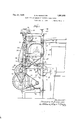
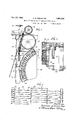
Referring now to the drawings more in detail'wherein like numerals have been employed throughout the various figures to designate similar parts, it will be observed that one embod ment of the invention includes a lower endless conveyor means which I have designated generally by the numeral 10 and an upper conveyor means 12. The lower conveyor 10 includes an endles belt 14, the upper reach of which passes through a refrigerator 16 in the direction indicated b the arrow inFigure 3. The upper reach of the belt 14 moves horizontally'to a point where it passes over and downward from a guide roll 18 which is carr ed at the outer extremities. of angularly adjustable arms 20. The arms are mounted upon opposite extremities of a shaft 22 wh ch supports a guide roll 24: for receiving the belt as it passes downwardly from the roll or shaft18. This shaft 22 is mounted within upright sections of a machine frame 25. As candy mater al which I have shown in the drawings as. bars 26. reaches the forward end' of the conveyor 10, it is delivered to another endless conveyor 28. This endless conveyor 28 comprises a plurality of wire links 30 which are clearly shownin Figure 6. Each link 30 extends from one side of the machine to the other and includes'a plurality of U-shaped sections made up of elongated horizontal portions 32 and relatively shortlink sections 34. Referring to Figure 3, it will be seen that this endless mesh-like conveyor 28 passes upwardly andover a guide shaft 36 so as to receive the candy bars 26' from the conveyor 10. A pair of spaced arcuate guide-bars 38 which are secured at their upper extremities to the frame 25 by means of bolts 40, serve to guide the conveyor 28 in proper spaced relation with respect to a rotary feeding means 42, about to be described. As the mesh-like conveyor 28 leaves the guide bars 38, it passes over a positively driven roll or drum 44 and then downwardly andunder an idler roll 46. The driven roll or, drum 44 is provided with a plurality of longitudinal grooves 48 (Fig-' ure 2) for receiving the sections 32 of the links 30 and a plurality of circumferential grooves 50 for accommodating the links sections 34. To further insure the meshing of the links 30 with the drum 44 I provide an idler roll 52 which bears downwardly upon the drum 44 through the action of coil'springs 54 which are interposed between pivotally mounted supporting arms 56 and the ma-' chine frame, as clearly shown in Figure 4; I prefer to use cushion-like material such as rubberfor the'peripheral portions of the rolls 44 and in order toprevent the links 30' from bein'gdistorted in response to the driving action of the positively drivenroll 44.
Referring now to Figures 3- and 4, it will beseen that the candy bars 26 are advanced by the conveyor 28 into engagement with relatively-soft bristles or'brushes 58 which are mounted within a drum 60 of the rotary conveyor means 42. The mesh-like conveyor 28 and the bristles 58 engage the opposite sides of the candy bars with sufficient gentleness to positively preclude the possibility of marring or otherwise disfiguring said candy and at the same time impart atractive force which is sufiicient to positively move the bars along a predetermined arcuate path. Both the flexible conveyor 28 and rotary means 42 are positively driven in timed relation by means later to be described, so thatrthere will be no relative movement between the links 30 and the bristles 58. It will be seen from Figure 4 that the flexibility or cushion-like action'of the linksand bristles is such as to automatically effect conforma tion of'said links and bristles to the particular surface contour of the: candy stock and thereby cause the positive, yet gentle advancement thereof. By having this arrangement, goods of varied sizes and shapes may be expeditiously conveyed from the lower conveyorto the upper conveyor or vice versa. In order to adjust thepositionof the guide bars 38 and thereby properly position the conveyor 28 with respect to the bristles 58, I
irovide screws 62 Fi ures 4 and 5. One ex tremity of these screws extends through a bracket 64 carried by the frame '25 and the opposite extremity of each screw makes a' threaded connection with an arm 66 which is riveted to the guide bar 38 Thus, these guide bars may be adjusted so as to properly space the conveyor links 30 from the bristles.
In order't-o vertically adjust the position of the rotary conveyor means 42, I provide four vertically disposed screws 68, two at each side of the machine frame. A pair of transverse frame members 69 and 70 are adapted to be vertically adjusted by means of the screws 68. The frame members 69 provide the support for bearings 7 2 Figure 1) in which the conveyor drum ($0 is rotatable. Thus, by manipulating the screws 68, the drum 60 may be vertically adjusted. The screws 68 serve also as a means for vertically adjusting the roll or drum 44: which is mounted in bearings 74, Figure 1, carried by the frame members 70. In this manner the tautness of the flexible conveyor 28 may be adjustably controlled. The screws 68 are provided with suitable hand wheels 76.
As the candy bars are moved away from the conveyor 28 through the action of the bristles 58, they are subsequently delivered to the upper reach of a belt 78 of the conveyor 12. The belt 78 moves in the direction indicated by the arrow in Figure 3 and thus the candy bars which are now inverted, are conveyed in a direction which is reverse to the direction of feed of the lower belt 14.
The driving mechanism for the above described machine includes a motor 80 or other suitable actuator and this motor is connected with a gear 82, Figure 1, by a chain 84. The gear 82 drives a shaft 86, which in turn drives a gear 88 through a chain 90. The gear 88 drives a shaft 92 and a gear 94 at the extremity of the shaft 92 is connected with a large gear 96 by a chain 98. This large gear rotates the shaft which supports the conveyor drum 60. Rotation is imparted to the roll or drum 4% which carries the conveyor 28 through the agency of gears 1.00 and 102, a shaft 104- and a chain drive 106. The timing is such that the speed of travel of the meshlike conveyor 28 is equal to the peripheral speed of the rotary conveyor means 42.
From the foregoing description it will be clear that my invention contemplates the provision of an improved, practical device for conveying candy goods and the like. By employing this apparatus, dipped candy may be moved in a given direction through a cooling chamber in one plane, shifted to another plane in an inverted position and then moved in a reverse direction. The practical advantages which flow from this improved construction will be more apparent when it is understood that heretofore it has not been possible to reverse the travel of the candy stock. In other words, my invention makes it possible to use the space above the lower endless conveyor and thereby enables a considerable saving in floor space. As stated above. it has heretofore been necessary for attendants to manually remove the goods as it reached the extremity of the conveyor, place them in a container and then carry them to the second dipping machine. My invention eliminates those steps by automatically shifting the goods from one path to another and in this manner enables said goods to be returned for a second dipping operation. In instanceswhere it is desirable to invert the goods so as to present the same in proper position for a subsequent treating step or for purposes of packing, my invention has a very practical application. The manner in which I have arranged the flexible conveyor 28 and the resilient or cushion-like bristles 58 positively avoids breakage and marring of the goods. This is of particular significance in handling chocolate coated candies and the like. The described device is not limited for use with hard candies but may be used with equal effectiveness for conveying chocolate coated candies having soft centers. This is accon'iplished by reason of the gentle clamping action of the conveyor 28 coupled with the fact that the links of said conveyor as well as the bristles, are self-conformable to the surface contour of the candy stock. Thus my machine is designed to handle goods which vary in size and shape over a comparatively wide range. While I have preferred to describe my invention in connection with the handling of candy material, it should be understood that said invention is by no means limited to that particular field but may be used in any instances where goods must be conveyed from one point to another and also in instances where the goods are of such a nature that they must be handled delicately.
Having thus described my invention, what I claim as new and desire to secure by Letters Patent is:
1. In a conveyor device of the class described for candy goods and material of like nature, a rotary drum device having a cushion-like peripheral portion for directly engaging and receiving material to be conveyed, and a conveyor means positively movable in timed relation with respect to and adjacent the peripheral portion of said rotary means and adapted to cooperate therewith in conveying material positioned therebetween.
2. In a conveyor device of the class described for shifting candy material and the like from one plane'to another, a rotary conveyor drum having a peripheral portion for directly engaging and receiving the material to move it in an arcuate path, and a second conveyor means spaced from and movable in an arcuate path corresponding to said first mentioned conveyor means whereby material positioned between and engaged by said conveyor means may be shifted from a given plane through an arcuate path to another plane spaced from said first mentioned plane.
3. In a conveyor device of the class described for candy and materialof like nature, a conveyor means for advancing material alonga plane in a given direction, a second conveyor means spaced from said first means for advancing material in another direction, rotary drum conveyor means having a peripheral surface for directly engaging and terial, and candy engaging means movable.
with and spaced from the periphery of said rotary conveyor means.
p4. In a conveyor device of the class described for displacing material from one vertical position to another, a rotary drum having a cushion-like peripheral surface for receiving material, and a flexible conveyor means movable in timed relation with respect to the cushion-like peripheral portion of the rotary means, said flexible conveyor drum being spaced from said peripheral portion so as to enable the material to be frictionally engaged but gently gripped between said flexible and cushion-like parts, and thereby effect the vertical displacement of said material. V
5. In a conveyor device of the class described, a rotary means having a plurality of. peripherally arranged bristles, said bristles providing a cushion-like material receiving surface, and means spaced from and cooperating with said bristles to hold materialin position upon said bristles, thereby effecting the conveyance of said material from one-position to another.
6. In a conveyor device of the class described, an endless conveyor for receiving and conveying candy material in a given direction, a rotary conveyor drum mechanism having a cushionlike peripheral portion for receiving and engaging the outer surface of said candy material without causing any disfigurement thereof, a second endless conveyor mechanism for receiving candy material from said first endless conveyor mechanism, said second conveyor mechanism being spaced from and movable in timed relation with a portion of the periphery of said rotary conveyor mechanism and cooperating therewith to hold the candy against the drum periphery and thereby effect the shifting of the candy from the first conveyor mechanism to a ver tically displaced position, and a third endless conveyor mechanism adapted to receive the candy material from the peripheral surface of said rotary conveyormech'anism.
7. In a conveyordevice of the class described, a rotary conveyor means having a cushionlike peripheral surface for directly receiving and engaging a surface of impressionable material without disfiguring the surface of said material, and a second conveyor mechanism spaced from and movable in timed relation with the peripheral surface of said ment.
engaged by the cushionlike periphery of the rotary conveyor mechanism and hold the impression able material against said periphery, whereby to eflect the displacement of said material from one position to another through an arcuate path without subjecting the surfaces of said material to any disfigure- In witness whereof, I scribed my name.
DOMINICK M. BERNOTOW.
have hereunto sub-
Priority Applications (1)
| Application Number | Priority Date | Filing Date | Title |
|---|---|---|---|
| US420250A US1891908A (en) | 1930-01-11 | 1930-01-11 | Means for and method of handling candy goods |
Applications Claiming Priority (1)
| Application Number | Priority Date | Filing Date | Title |
|---|---|---|---|
| US420250A US1891908A (en) | 1930-01-11 | 1930-01-11 | Means for and method of handling candy goods |
Publications (1)
| Publication Number | Publication Date |
|---|---|
| US1891908A true US1891908A (en) | 1932-12-27 |
Family
ID=23665695
Family Applications (1)
| Application Number | Title | Priority Date | Filing Date |
|---|---|---|---|
| US420250A Expired - Lifetime US1891908A (en) | 1930-01-11 | 1930-01-11 | Means for and method of handling candy goods |
Country Status (1)
| Country | Link |
|---|---|
| US (1) | US1891908A (en) |
Cited By (4)
| Publication number | Priority date | Publication date | Assignee | Title |
|---|---|---|---|---|
| US2421801A (en) * | 1941-09-22 | 1947-06-10 | Gromiller Inc | Apparatus for fusing the coating on tablets |
| US2650690A (en) * | 1950-12-13 | 1953-09-01 | Horace D Hume | Trailer type crop loader |
| US2892462A (en) * | 1954-12-30 | 1959-06-30 | Frank H Ine | Shrink tank for packaged articles |
| US2896763A (en) * | 1954-07-23 | 1959-07-28 | Lehigh Inc | Vending machine |
-
1930
- 1930-01-11 US US420250A patent/US1891908A/en not_active Expired - Lifetime
Cited By (4)
| Publication number | Priority date | Publication date | Assignee | Title |
|---|---|---|---|---|
| US2421801A (en) * | 1941-09-22 | 1947-06-10 | Gromiller Inc | Apparatus for fusing the coating on tablets |
| US2650690A (en) * | 1950-12-13 | 1953-09-01 | Horace D Hume | Trailer type crop loader |
| US2896763A (en) * | 1954-07-23 | 1959-07-28 | Lehigh Inc | Vending machine |
| US2892462A (en) * | 1954-12-30 | 1959-06-30 | Frank H Ine | Shrink tank for packaged articles |
Similar Documents
| Publication | Publication Date | Title |
|---|---|---|
| US3240311A (en) | Conveyer for articles such as confections | |
| US2154844A (en) | Conveyer chain | |
| US2372646A (en) | Conveying mechanism | |
| JP2529721Y2 (en) | Packaging machine | |
| US2732987A (en) | moore | |
| US3444982A (en) | Device for handling and positioning articles within containers | |
| US3900096A (en) | Feeding mechanism for wrapping machine | |
| US1891908A (en) | Means for and method of handling candy goods | |
| US3694999A (en) | Box lidding machine | |
| US3353652A (en) | Feeding and indexing device for package handling apparatus | |
| US2322221A (en) | Soldering machine | |
| US3084491A (en) | Means for transporting flexible sheets | |
| US1673686A (en) | Machine for coating or incrusting confectionery, biscuits, and the like | |
| CN215885077U (en) | Article conveying device | |
| US2872768A (en) | Apparatus for wrapping lollipops and the like | |
| US2346776A (en) | Sealing apparatus | |
| CN113401580A (en) | Article conveying device | |
| US2592141A (en) | Article arranging apparatus | |
| US2512073A (en) | Packaging machinery | |
| US2850148A (en) | Frozen confection distributor | |
| US2370188A (en) | Can uprighting device | |
| US2770349A (en) | Conveyor mechanism for dividing single line of articles into double line | |
| US3141279A (en) | Carton flap-opening apparatus | |
| US2484095A (en) | Conveyer apparatus for use in the assembly of closure caps | |
| US2873841A (en) | Orientating apparatus |