US1887828A - Lamp control for vehicles - Google Patents
Lamp control for vehicles Download PDFInfo
- Publication number
- US1887828A US1887828A US561025A US56102531A US1887828A US 1887828 A US1887828 A US 1887828A US 561025 A US561025 A US 561025A US 56102531 A US56102531 A US 56102531A US 1887828 A US1887828 A US 1887828A
- Authority
- US
- United States
- Prior art keywords
- lamp
- lamps
- bar
- dipping
- shaft
- Prior art date
- Legal status (The legal status is an assumption and is not a legal conclusion. Google has not performed a legal analysis and makes no representation as to the accuracy of the status listed.)
- Expired - Lifetime
Links
- 238000007598 dipping method Methods 0.000 description 42
- 230000033001 locomotion Effects 0.000 description 21
- 230000005540 biological transmission Effects 0.000 description 3
- 238000012986 modification Methods 0.000 description 3
- 230000004048 modification Effects 0.000 description 3
- 230000007423 decrease Effects 0.000 description 2
- 238000005286 illumination Methods 0.000 description 2
- 238000000034 method Methods 0.000 description 2
- 229920000136 polysorbate Polymers 0.000 description 2
- 101000635799 Homo sapiens Run domain Beclin-1-interacting and cysteine-rich domain-containing protein Proteins 0.000 description 1
- 241001446467 Mama Species 0.000 description 1
- 102100030852 Run domain Beclin-1-interacting and cysteine-rich domain-containing protein Human genes 0.000 description 1
- 238000013459 approach Methods 0.000 description 1
- 238000010276 construction Methods 0.000 description 1
- 230000007547 defect Effects 0.000 description 1
- 230000000694 effects Effects 0.000 description 1
- 210000003414 extremity Anatomy 0.000 description 1
- 230000003014 reinforcing effect Effects 0.000 description 1
Images

Classifications
-
- B—PERFORMING OPERATIONS; TRANSPORTING
- B60—VEHICLES IN GENERAL
- B60Q—ARRANGEMENT OF SIGNALLING OR LIGHTING DEVICES, THE MOUNTING OR SUPPORTING THEREOF OR CIRCUITS THEREFOR, FOR VEHICLES IN GENERAL
- B60Q1/00—Arrangement of optical signalling or lighting devices, the mounting or supporting thereof or circuits therefor
- B60Q1/02—Arrangement of optical signalling or lighting devices, the mounting or supporting thereof or circuits therefor the devices being primarily intended to illuminate the way ahead or to illuminate other areas of way or environments
- B60Q1/04—Arrangement of optical signalling or lighting devices, the mounting or supporting thereof or circuits therefor the devices being primarily intended to illuminate the way ahead or to illuminate other areas of way or environments the devices being headlights
- B60Q1/06—Arrangement of optical signalling or lighting devices, the mounting or supporting thereof or circuits therefor the devices being primarily intended to illuminate the way ahead or to illuminate other areas of way or environments the devices being headlights adjustable, e.g. remotely-controlled from inside vehicle
- B60Q1/08—Arrangement of optical signalling or lighting devices, the mounting or supporting thereof or circuits therefor the devices being primarily intended to illuminate the way ahead or to illuminate other areas of way or environments the devices being headlights adjustable, e.g. remotely-controlled from inside vehicle automatically
- B60Q1/12—Arrangement of optical signalling or lighting devices, the mounting or supporting thereof or circuits therefor the devices being primarily intended to illuminate the way ahead or to illuminate other areas of way or environments the devices being headlights adjustable, e.g. remotely-controlled from inside vehicle automatically due to steering position
- B60Q1/124—Arrangement of optical signalling or lighting devices, the mounting or supporting thereof or circuits therefor the devices being primarily intended to illuminate the way ahead or to illuminate other areas of way or environments the devices being headlights adjustable, e.g. remotely-controlled from inside vehicle automatically due to steering position by mechanical means
Definitions
- This invention relates toswivellingappa intlus for a. pair-jot vehicle head lamps; dis
- a further; object of; the invention is to provide improved di'pping;apparatus to be associated with the lampzswivelling apparatus, but capable of being operatediindependently thereof, and when: the swivelling apparatus is innormalor zero positionwithout: affecting incorrect: rotation of; the lamps.
- the corresponding lamp whenvthe vehicleiis turned'ieither tolthe right or to the left, thecorresponding lamp is arranged to be, swivelled withthe other lamp-remaining stationary.
- This arrangement allows of-the inner. sideofthe curve to be effectively illuminatedeandthe boundary of the road asthevehicle. is turned to he sufiiciently illuminated, so; that objects can be clearly defined 7
- the essential featureof thepresent invention is a single pivotal bar-, whichyisloeated between the lampsand has its.
- The. invention ispreferablyappliedto motor-;vehicles,but it should ibeeundersteod that theinventionis also applicable to;any vehicle constructed with,v steering apparatus. which may be turned so that the lampsfanticipate the movement of; the; vehicle. i
- the connecting rod for, actuating the. pitotaLbar-trom thezsteering is connected inthe axisaoithedipping shaft.
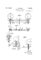
- Fig. 1 is a diagrammatic view, looking from the frontof the vehicle, of one form of the mechanism according to the invention without dipping gear; W
- Fig. 2 is a plan View of Fig. 1 showing the position of the parts with the right hand lamp actuated;
- Fig. 3 is a modified arrangement in which dipping mechanism is associated with the swivelling apparatus
- Fig. i is a plan view of Fig. 3 with the lamps removed; J
- Fig. 5 is an end elevation of Fig; 3"and illustrates more clearly the dipping mechanism and the control of the swivelling apparatus by a pull rod
- Fig. 6 is a modified combined swivelling and dipping mechanismin which a reversing mechanism is eliminated and the supports on the dipping shaft are placed intermediate of the lamps instead of externally thereof as shown in Fig. 3; 1
- Fig.7 is a plan view of Fig. 6 with the lamps removed; a
- Fig. 8 is a side elevation ofFig. 6 showing the connecting rod of the mechanism actuating the swivelling apparatus connected to thefpivotal bar in the axis of the dipping s a t;
- Fig. 9 is a detail view of one form of bearings for the lamp stems and the preferred means employed for restoring to and mamtaining a lamp in the normal or stralght ahead position.
- the lamps 1 are mounted in any convenient manner on stems or spindles 2 which in turn are rotatably'mounted in flanged support as shown in Fig. 9, wherein each;- bearing 3 is provided with a sleeve 5 in which the'lamp stem 2 ismounted.
- a small pin 6on the lamp stem is arranged to project through a circumferential slot 7 in the sleeve 5 and a helical spring 8 surrounds the sleeve 5, being fixed at one end to a fianged and threaded enlarged end 9 of the sleeve 5 and attached at its other end to the pin 6 riding in the 60 circumferential slot 7
- the pin 6 normally pressure from the spring, to thereby'maintain the lamp in the normal or straight ahead abuts against one end of the slot 7 under position when the bearing 3 is screwedinto
- the lamp support bearing described above is by way of example only, and may be modified according to requirements, and further the bearing instead of being screwed into the .cross bar may be welded thereon, or may be clipped to or mounted on lugs attached to the bar.
- apparatus for dipping the lamps is not pro- -motor car, may be conveniently the usual cross stay betweenthe front wings of the chassis of the car.
- the lamps l are each mounted in position at the respective sides of the car by securing the bearings 3 thereof into the cross stay as described above.
- a single bar 14 is pivoted centrally of the two lamps and rigidly secured to each of the lamp stems, preferably above the collars 4: as shown, is a laterally projecting arm or finger 11 which, in the normal straight ahead position of the associated lamp, points inwardly along the cross bar towards the other lamp.
- Fix-edly mounted intermediate of the two lamps l on the cross bar 10 is a further hearing 18, in which is rotatably'mounted a pin 12 carrying the pivotal bar 14 the ends of which bar include vertical pins 15, 16 freely engaging with the projecting fingers 11, so as to wipe the inner sides of the said fingers with the result that. as the bar 14: is rotated one lamp will be turned differentially and at a rate which progressively decreases towards the latter stages of the turn, while the other lamp remains stationary by reason of the end of the bar moving away from the associated finger.
- a reciprocating connecting rod 17 controlled from the steering mechanism is connected by a ball or universal joint, to one end of the pivotal bar 14, preferably the right hand or off-side end, and is arranged to produce "an angular movement of'the pivotal bar, and consequently a reciprocating motion at either end of the latter in accordance with the movement of thesteering mechanism, the pivotal bar 14 in its normal position being arranged'with its horizbntal axis parallel to the axis of the cross stay 10.
- the lamps 1 are arranged tobe operated in such a manner that when the car is turned to the right, the right hand straight ahead position.
- Rotation of the lamps is allowed by the slots 7 in the sleeves 5 of the bearings 3, in which slots ride the pins 6 on the lamp stems 2, tension being stored, up in. the spring 8 of the operated lamp so that when. the pivotal bar 14 is restored to its zero position parallel with the cross bar 10, the operated lamp is also restored by the spring 8, the associated pin 6 abutting against the forward end of the slot 7 when the normal or straight ahead position of the lampis reached.
- the pin ridingin the slot in the bearing of the lamp, together-with the slot could be dispensed with, and a fixed pin, preferably on the cross stay, provided secured in such a position that the finger 11 on the lamp spindle 2 engages therewith in the normal position under, spring pressure.
- the cross bar 10- is constituted by a shaft 18 which is rotatably mounted in fixed bearings secured, for example, to the'chassis of the car. 1 1
- thelamps 1 are each mounted as beforein bearings '3 and are provided with similar means for restoring to and maintaining them injthe straight ahead position, aprojecting finger 11 being also similarly secured to each lamp spindle 2.
- the pivotal bar 14 is as before mounted in a bearing 13 intermediate "of the lamps 1 and is provided :at eachendwith similar pins 15, 1-6 which abut against the respective'inne-r sides-of the fingers 11 of the two'lamps.
- the end of the connecting rod 17 is arranged to be brought into the horizontal axis of the dipping shaft 18. This is accomplished by forming the dipping shaft18 with a slot or recess intermediate of the *two lamps, and suitably reinforcing the bar at this point.
- a U shaped member-21 may be formed in the bar, between the jaws of which the end of the rod 17 is connected in the centre line of the dipping shaft, by means of a ball or universal joint to a pin or extension 22- on the pivotal bar 14, depending into the slot or U shaped member 21.
- a lever v 23 preferably formed as an extension of one of the jaws. of theU shaped member.
- This lever 23 is connected by toggle mechanism comprising a pair of toggle levers 24 and 25, to a rigid pin 26 attached to a convenient part of the chassis or any other fixed point.
- a pull rod 27 ' is secured; to one of the toggle levers preferably at the hinge of the toggle and is operativelyconnected such as byBowden cable tosuitable control mechanism operable by the driver of the car.
- pull rod 27 will bring the'togglemechanism into the position shown indotted lines in Fig. 5, thereby rotating the shaft 18 downwardly and causing the beam from the lamps to' dip.
- Suitable means suchas a spring, not shown, being provided for returning the dipping shaft to normal position when the control mechanism is released.
- Limiting stops 28 and 29- are preferably provided for limiting the backward and for"- ward movement of the toggle levers 24, 25, these stops respectively being conveniently the pivotal bar 14 is effected by a connecting rod 17 controlled from the steering mechanism, and it is necessary that movement of the connecting rod in a forward direction produced rotation of the right hand lamp, while movement of the connecting rod in a backward direction produces rotation of the left hand lamp, according as to whether the car is turned to the right or the left.
- the connecting rod 17 may correspond to the connecting rod 20 of British Patent Specification No. 278,464, and maybe controlled from the steering column by the transmission mechanism for actuating the swivelling apparatus therein described and shown, with the exception that it will be necessary to interpose a reversing link such as 30 whereby the correct movement is given to the rod 17 when the car is turned.
- the pivotal bar 14 is so formed or constructed that the i and therefore rotate the fingers 11 in the opposite sense.
- the pivotal bar 14 is provided with curved ends 31, which respectively pass beyond and embrace the lamp spindles 2, the vertical pins 15, 16 being secured to the respective ends 31 preferably near the ext-rem ities thereof and co-operating with the fingers 11 on the lamps, which in this case, however, are mounted in sucha manner that they point in a direction away from each other.
- the pins 15, 16 on the pivotal bar 14 in this case abut against the outer facesof the fingers.
- the pivot point of the pivotal bar may be offset from the verse shaft.
- the connecting rod 17 conaxis of the transtrolled from the'steering mechanism is connected in'the axis of the dipping shaft 18 by means of a ball or universal joint 32 to a depending pin or extension 33 at'theright hand ,end of the pivotal bar '14, whereby the rod 17 is caused to reciprocate across the axis of the dipping shaft 18 to ensure that no relative movement of the pivotal bar 14 occurs when dipping of the lamps is effected, more particularly in the zero or normal position of the 1 bar 14.
- V Dipping apparatus similar to that described in connection with the previous modification may be attached to thecdipping shaft 18 in any convenient manner, for example, by
- Swivelling apparatus for a pair of vehicle head lamps disposed oneon each side of the vehicle with restoring means for returning the lamps to initial position, the vehicle including steering mechanism, compris-.
- 2/ Swivelling apparatus for a pair of vehicle head lamps disposed one on each side of the vehicle with restoring means for returning the lamps to initial position, the vehicle includingsteering mechanism, co1nprising in combination with apair of laterally projecting arms, one for each lamp, a single pivotal bar, means for mounting the bar between the lamps with the end of said bar freely engaging the said laterally projecting arms, so as to produce a reduced rate of turning of a lamp towards the latter stages of the turning, and connecting means for rotating the said bar from the steering mechanism of the vehicle in accordance with the direction turned.
- Swivelling apparatus for a pair of vehicle head lamps, the vehicle including steering mechanism, a dipping shaft carrying the said lamps one on each side of the vehicle with restoring means for returning the lamps to initial position, and means for rotating the clipping shaft, comprising in combination with a pair of projecting arms.
- Swivelling apparatus for a pair of vehicle head lamps, the vehicle including steering mechanism, a dipping shaft carrying the said lamps one on each side of the vehicle, with restoring means for returning the lamps to initial position, and means for rotating the dipping shaft, comprising in combination with a pair of laterally projecting arms, one for each lamp, a single pivotal bar, means for mounting the bar on the dipping shaft between the lamps with the ends of the said bar freely engaging the said laterally projecting arms, so as to produce a reduced rate of turning of a lamp towards the latter stages of the turning, connecting means for rotating the said bar from the.
- a vehicle including a chassis and steering mechanism, the combination of a pair of lamps," a pair of supports mounted one-on each side of the chassis, lamp spindles to the lamps rotatably mounted in said supports, restoring means for returning the lamps to initial position when turned, an arm on each lamp spindle projecting inwardly toward the other, a bearing mounted on the chassis between the lamps, a single bar pivoted centrally between the lamps in the said bearing with the ends of the said bar freely engaging the said inwardly projecting arms; and a reciprocating rod connecting the said bar with the steering mechanism for rotating thebar in accordance with the direc-' ing the said outwardly projecting arms, and I a reciprocating connecting rod connecting the said bar with the steeringmechanism for rotating the bar in accordance with the direction steered.
- a dipping shaft rotatably mounted on the chassis, a pair of lamps, a pairof lamp support'smounted one on each side ofthe dipping shaft, lamp spindlesto the lamps, rotatably mounted in said supports, restoring means for returning the lamps to initial position when turned, an arm on each lam spindle projecting inwardly toward the other, a bearing mounted on the dipping shaft between the lamps, a single bar pivoted centrally between the lamps in the said bearing with the ends of the said bar freely engaging the said inwardly projecting arms, means for rotating the dipping shaft, a reciprocating connecting rod extending to the steering mechanism forreciprocation thereby according to the direction steered, an extension to said bar on one side of the pivot thereof, the said extension depending into a recess in the said shaft and an operative connection beping shaft rotatably mounted on the chassis,
- a pair of lamps a pair of lamp supports mounted one on each side of the dipping shaft, lamp spindles to the lamps rotatably mounted on said supports, restoring means and 7 for returning the lamps to initial position when turned, an arm on each lampspindle projecting outwardly away from the other, a bearing mounted on the dipping shaft be tween the lamps, a single bar pivoted centrally between the lamps in the said bearing, curved ends to the said bar embracing the lamp spindles and freely engaging the said outwardly projecting arms, means for rotat- 10 ing the dipping shaft, a reciprocating connecting rod extending to the steering mechanism forsreciprocation thereby according to the direction steered, and means for connecting one end of the connecting rod to the said bar on one side of the pivot thereof in the horizontal axis of the dipping shaft.
- a pair of lamps a pair of lamp supports mounted-one on each side of the dipping shaft, lamp spindles to the lamps rotatably mounted on said supports, restoring means for returning the lamps to initial position when turned, an arm on each'lamp spindle projecting outwardly away from the other, a bearing mounted on the dipping shaft be- 7 tween the lamps, a single bar pivoted centrally between the lamps in the said bearing,
Landscapes
- Engineering & Computer Science (AREA)
- Mechanical Engineering (AREA)
- Lighting Device Outwards From Vehicle And Optical Signal (AREA)
Description
Nov; 15, 1932. J. 5. TRITTON LAMP CONTROL FOR VEHICLES 2 SheetsSheet 1 Filed Sept. 3, 1931 all- 51G 11 INVENFUE' 1 s. Farr-r014. Pan ATTORNEY Nov. 15, 1932. J. s. TRlTTON 1,887,828
LAMP CONTROL FOR VEHICLES Filed Sept. 5, 1931 2 Sheets-Sheet 2 A-rfcmrlay Patented Nov. 1932 UNITED. "S AT- 3 airmen sniznounmnmronliv-orf.cnllcnrrmginnmi iIaAMPiOONTROL FQR VEHICLES Application-filedSeptember 2 -1931, SeriarNo; 561;025,-and-'in flreavmitain September-1 6; 1920;; Y
This inventionrelates toswivellingappa intlus for a. pair-jot vehicle head lamps; dis
posed; one each side of, the YQlIiClGJ-fOI the purpose "of giving; ai more -efi'ectiveillumina- 5 tion; when. turning corners, and under any otheitconditions.v p a I Withlamps asat: present in; use which; only throw a, straight. beam; forward-,1 a; defect is experienced in that they donot illuminate theoif or thetnearrsidepf,the-road untiliallmost completely, roundthe corner; according as; a: car is a turning to the right or the left, and in order to overcome this-disadvantage itzhaszheretofore; been; proposed to: allow-one lamp off'a' p air: Whicl1-,n0rmally: illuminates one side ofthe-road to maintain" its normal illumination, and-.to cause the second lamp to be movedso asto illuminatea line other than it would, normally illuminate when-actingas a fixed lamp; Thus according as-to Whichdimotion the car is turnedione oft-he lamps remains stationary, while the other; is-turned in the 'same direction as the, vehicle.
The apparatus necessary to obtain. this result has. heretofore: been: somewhat comparatively complicatedqand expensive; and it is the object of the present inventionrt'osimplif'y-the method andapparatus, and; to improve-the efficacy thereof.
A further; object of; the invention is to provide improved di'pping;apparatus to be associated with the lampzswivelling apparatus, but capable of being operatediindependently thereof, and when: the swivelling apparatus is innormalor zero positionwithout: affecting incorrect: rotation of; the lamps.
In a. preferred, methodaccording to. this invention, whenvthe vehicleiis turned'ieither tolthe right or to the left, thecorresponding lamp is arranged to be, swivelled withthe other lamp-remaining stationary. This arrangement allows of-the inner. sideofthe curve to be effectively illuminatedeandthe boundary of the road asthevehicle. is turned to he sufiiciently illuminated, so; that objects can be clearly defined 7 The essential featureof thepresent invention is a single pivotal bar-, whichyisloeated between the lampsand has its. ends freely engagingprojecting arms ontthe lamps, this bar being; connectedto a the: steering; mechanism of the vehicle so that whenjthelattei' negotiates arturnthe ibar is rotatedjin a particular direction. Consequently, one of the endsof the bar will abutthearm on'one lamp and cause the latter togturnzw-ith aiharmonic ordifierential.movementpwhilethe other end WlllIQlZftliB:21-W 4y;fI0m.tl1QOl he1l lampleav-ing in stationary. inithe initial; position; a When the; annsproject laterally; eithertoward one another: or away a from oneanother, the ditferential movement will be such asgto produce a; reduced irate ofitnrning ,off a lamp towards the latter stages of the turningzp 1 V Thus; atthecommencementof a, turn the appropriatezlamp will; move; more; quickly than-[the Wheels, whilstras the steeringgmech anism approaches full; lock the-speedoflrotation of the lamp will progressively decrease. p
Each la-mpis-controlledfbya spring memb.8111 which normally, maintainsa the lamp against, a stopfin the stationary,- straight ahead: osition, and returns it tostliis position When t e pivotal bar has heen-rcstoredxafter operatingthedamp;
The. invention;ispreferablyappliedto motor-;vehicles,but it should ibeeundersteod that theinventionis also applicable to;any vehicle constructed with,v steering apparatus. which may be turned so that the lampsfanticipate the movement of; the; vehicle. i
As, hereinbefore mentioned, the'invention EtlSOvBIHbQdlQS apparatus.- for; dipping the lampsiwhichisassociatedtwith thesvvivelling ly-thereof-asdesiredi V r y Accordingly:theilampsgarepreierablysupported. on} a. transverse: shaft'hereinafter termed a. dipping; shaft, which isicapable of rotationiin fixedibearingssecuredzto-the,chas- I apparatusbut.may beeoperated independent 5 sis of; the: vehicle, the dipping shaftalso car- .rying the pivotal har member;
To prevent the dipping ;motioniproducing swivelling ofthe lamps, more particularly in the: zero or normal. position. thereof; the. end
of; the connecting rod for, actuating the. pitotaLbar-trom thezsteering is connected inthe axisaoithedipping shaft.
Theo-invention willhe; more clearly understood; withreference to the following; de-
scription taken in conjunction with the accompanying drawings, which show by way of example two embodiments of the invention as applied to the control of a pair of lamps.
In the drawings Fig. 1 is a diagrammatic view, looking from the frontof the vehicle, of one form of the mechanism according to the invention without dipping gear; W
Fig. 2 is a plan View of Fig. 1 showing the position of the parts with the right hand lamp actuated;
Fig. 3 is a modified arrangement in which dipping mechanism is associated with the swivelling apparatus;
Fig. i is a plan view of Fig. 3 with the lamps removed; J
Fig. 5 is an end elevation of Fig; 3"and illustrates more clearly the dipping mechanism and the control of the swivelling apparatus by a pull rod Fig. 6 is a modified combined swivelling and dipping mechanismin which a reversing mechanism is eliminated and the supports on the dipping shaft are placed intermediate of the lamps instead of externally thereof as shown in Fig. 3; 1
Fig.7 is a plan view of Fig. 6 with the lamps removed; a
Fig. 8 is a side elevation ofFig. 6 showing the connecting rod of the mechanism actuating the swivelling apparatus connected to thefpivotal bar in the axis of the dipping s a t;
Fig. 9 is a detail view of one form of bearings for the lamp stems and the preferred means employed for restoring to and mamtaining a lamp in the normal or stralght ahead position.
The lamps 1 are mounted in any convenient manner on stems or spindles 2 which in turn are rotatably'mounted in flanged support as shown in Fig. 9, wherein each;- bearing 3 is provided with a sleeve 5 in which the'lamp stem 2 ismounted. A small pin 6on the lamp stem is arranged to project through a circumferential slot 7 in the sleeve 5 and a helical spring 8 surrounds the sleeve 5, being fixed at one end to a fianged and threaded enlarged end 9 of the sleeve 5 and attached at its other end to the pin 6 riding in the 60 circumferential slot 7 The pin 6 normally pressure from the spring, to thereby'maintain the lamp in the normal or straight ahead abuts against one end of the slot 7 under position when the bearing 3 is screwedinto It will be understood, however, that the lamp support bearing. described above is by way of example only, and may be modified according to requirements, and further the bearing instead of being screwed into the .cross bar may be welded thereon, or may be clipped to or mounted on lugs attached to the bar. i
In the simplest form of the invention apparatus for dipping the lamps is not pro- -motor car, may be conveniently the usual cross stay betweenthe front wings of the chassis of the car. The lamps l are each mounted in position at the respective sides of the car by securing the bearings 3 thereof into the cross stay as described above.
Referring now to Figs. 1 to 8 and first more particularly to Figs. 1 and 2, a single bar 14 is pivoted centrally of the two lamps and rigidly secured to each of the lamp stems, preferably above the collars 4: as shown, is a laterally projecting arm or finger 11 which, in the normal straight ahead position of the associated lamp, points inwardly along the cross bar towards the other lamp.
Fix-edly mounted intermediate of the two lamps l on the cross bar 10 is a further hearing 18, in which is rotatably'mounted a pin 12 carrying the pivotal bar 14 the ends of which bar include vertical pins 15, 16 freely engaging with the projecting fingers 11, so as to wipe the inner sides of the said fingers with the result that. as the bar 14: is rotated one lamp will be turned differentially and at a rate which progressively decreases towards the latter stages of the turn, while the other lamp remains stationary by reason of the end of the bar moving away from the associated finger. bearings 3 and maintained in position by Y It will be understood, however, that these pins are not essential, since the fingers could be arranged to engage directly with extensions on the ends of the pivotal bar, or the latter may be mounted in the same plane'as the fingers, which would then co-operate directly with the ends of the pivotal bar.
Preferably a reciprocating connecting rod 17 controlled from the steering mechanism is connected by a ball or universal joint, to one end of the pivotal bar 14, preferably the right hand or off-side end, and is arranged to produce "an angular movement of'the pivotal bar, and consequently a reciprocating motion at either end of the latter in accordance with the movement of thesteering mechanism, the pivotal bar 14 in its normal position being arranged'with its horizbntal axis parallel to the axis of the cross stay 10.
As previously mentioned, according to the preferred method, the lamps 1 are arranged tobe operated in such a manner that when the car is turned to the right, the right hand straight ahead position.
mamas order that the correct lamp may be rotated,
it is necessary to arrange that when the car is turned to the right, the connecting rod 17 controlling the angular movement of the pivotal bar l iis moved forwardly while when car is turned to the left, the rod 17 is movedbackwardly. i
Thlus, forward movement of the rod17 causes the finger 11 of the right hand lamp RL to rotate in clockwise direction asviewed in Fig. 2, and thereby rotation of the associated lamp in the same direction. The right hand lamp will, therefore, illuminate the off-side of the road and the left hand lamp will remain stationary, the parts being disposed as shown in Fig. 2.
Turning of the car to the left results in theconnecting rod 17 being moved backwards and the left hand pin 16 causing the finger 1 1 of the left hand lamp LL to be rotatedin aeounter clockwise direction to cause corresponding rotation of the associated lamp, and illumination of the near side of the road, the right hand lamp RL remaining station- It will be understood, therefore, that forward movement of the connecting rod causes the left hand pin to move away from the finger of the left hand lamp LL, while back- ":"zr. ward movement of the connecting rod causes the right hand pin to move away from the finger of the right hand lamp RL, the lamp which is not to be rotated being maintained in the straight ahead position by virtue of I the springs on the associated bearing 3.
Rotation of the lamps is allowed by the slots 7 in the sleeves 5 of the bearings 3, in which slots ride the pins 6 on the lamp stems 2, tension being stored, up in. the spring 8 of the operated lamp so that when. the pivotal bar 14 is restored to its zero position parallel with the cross bar 10, the operated lamp is also restored by the spring 8, the associated pin 6 abutting against the forward end of the slot 7 when the normal or straight ahead position of the lampis reached.
Since, therefore, the pins 6 are normally maintained against the forward end of the slots 7 in the respective bearings of the lamps,
it will be understood that when either lamp is rotated the other lamp is prevented from rotation, and is maintained in a direction parallel to the longitudinal axis of the car. It will be understood however, that this arrangement of restoring to and maintaining the lamps in a predetermined position is capable of modification, and the invention is "not to be considered limited to the preferred embodiment.
For example, the pin ridingin the slot in the bearing of the lamp, together-with the slot, could be dispensed with, and a fixed pin, preferably on the cross stay, provided secured in such a position that the finger 11 on the lamp spindle 2 engages therewith in the normal position under, spring pressure. 1
' To provide for the dipping of the lamps,
the cross bar 10- is constituted by a shaft 18 which is rotatably mounted in fixed bearings secured, for example, to the'chassis of the car. 1 1
In one construction according to Figs. 3, 4 and 5 embodying this mo dification, thelamps 1 are each mounted as beforein bearings '3 and are provided with similar means for restoring to and maintaining them injthe straight ahead position, aprojecting finger 11 being also similarly secured to each lamp spindle 2. The pivotal bar 14 is as before mounted in a bearing 13 intermediate "of the lamps 1 and is provided :at eachendwith similar pins 15, 1-6 which abut against the respective'inne-r sides-of the fingers 11 of the two'lamps.
In order that the dippingmotion of the lamps may not affect the swivel-ling motion, the end of the connecting rod 17 is arranged to be brought into the horizontal axis of the dipping shaft 18. This is accomplished by forming the dipping shaft18 with a slot or recess intermediate of the *two lamps, and suitably reinforcing the bar at this point. Conveniently a U shaped member-21may be formed in the bar, between the jaws of which the end of the rod 17 is connected in the centre line of the dipping shaft, by means of a ball or universal joint to a pin or extension 22- on the pivotal bar 14, depending into the slot or U shaped member 21.
Attached to the dipping shaft 18 is a lever v 23 preferably formed as an extension of one of the jaws. of theU shaped member. This lever 23 is connected by toggle mechanism comprising a pair of toggle levers 24 and 25, to a rigid pin 26 attached to a convenient part of the chassis or any other fixed point. A pull rod 27 'is secured; to one of the toggle levers preferably at the hinge of the toggle and is operativelyconnected such as byBowden cable tosuitable control mechanism operable by the driver of the car.
Backward movement of this. pull rod 27 will bring the'togglemechanism into the position shown indotted lines in Fig. 5, thereby rotating the shaft 18 downwardly and causing the beam from the lamps to' dip. Suitable means, suchas a spring, not shown, being provided for returning the dipping shaft to normal position when the control mechanism is released.
Limiting stops 28 and 29- are preferably provided for limiting the backward and for"- ward movement of the toggle levers 24, 25, these stops respectively being conveniently the pivotal bar 14 is effected by a connecting rod 17 controlled from the steering mechanism, and it is necessary that movement of the connecting rod in a forward direction produced rotation of the right hand lamp, while movement of the connecting rod in a backward direction produces rotation of the left hand lamp, according as to whether the car is turned to the right or the left.
, To effect this movement the connecting rod 17 may correspond to the connecting rod 20 of British Patent Specification No. 278,464, and maybe controlled from the steering column by the transmission mechanism for actuating the swivelling apparatus therein described and shown, with the exception that it will be necessary to interpose a reversing link such as 30 whereby the correct movement is given to the rod 17 when the car is turned.
It will be understood, however, that other transmission mechanism for efiecting the necessary movement of the lamps in accordance with the steering may be employed, or any alternative means which will produce correct reciprocation of the ends of the pivotal bar 14 when the steering gear is operated.
According, however, to a further modification of the invention, in which both dipping and swivelling movement of the lamps is preferably provided, although the clipping apparatus is not necessary thereto, the pivotal bar 14 is so formed or constructed that the i and therefore rotate the fingers 11 in the opposite sense. The pivotal bar 14 is provided with curved ends 31, which respectively pass beyond and embrace the lamp spindles 2, the vertical pins 15, 16 being secured to the respective ends 31 preferably near the ext-rem ities thereof and co-operating with the fingers 11 on the lamps, which in this case, however, are mounted in sucha manner that they point in a direction away from each other.
The pins 15, 16 on the pivotal bar 14 in this case abut against the outer facesof the fingers.
If necessary, the pivot point of the pivotal bar may be offset from the verse shaft. v
Preferably the connecting rod 17 conaxis of the transtrolled from the'steering mechanism, is connected in'the axis of the dipping shaft 18 by means of a ball or universal joint 32 to a depending pin or extension 33 at'theright hand ,end of the pivotal bar '14, whereby the rod 17 is caused to reciprocate across the axis of the dipping shaft 18 to ensure that no relative movement of the pivotal bar 14 occurs when dipping of the lamps is effected, more particularly in the zero or normal position of the 1 bar 14.
V Dipping apparatus similar to that described in connection with the previous modification may be attached to thecdipping shaft 18 in any convenient manner, for example, by
a similar outwardly extending lever 23 provided on a longitudinal extension of the dipping shaft 18 or intermediate of the lamps.
- With this arrangement, if the movement of the connecting rod 17 controlled from the steering mechanism is normally in a backward direction when the caris turned to the right, and forwardly when the car is turned to the left, it will be seen that rotation of the correct lamp is effected. Thus, when the car is turned to the right, the connecting rod 17 moves backwards to cause the finger 11 on the right hand lamp RLto rotate in a clockwise direction, and when the car is turned to the left the finger 11 on the left lamp LL is rotated in the same direction; it will, therefore, be possible to directly connect the rod 17 with transmission mechanism such as that shown and described in British Specification No. 278,464. I 1
It will be understood that any convenient means may be provided for effecting reciprocation of the ends ofthe pivotal bar, so long as the reciprocation is effected in accordance with the movement of the steering mechanism and'the correct lamp rotated. I
Further, it will also be understood that by causing the pins on the ends of the pivotal bar to abut against the other side of the fingers on the lamp spindles, turningof the car either to the right or the left will cause either the left or the right hand lamp to ro- 1. Swivelling apparatus for a pair of vehicle head lamps disposed oneon each side of the vehicle with restoring means for returning the lamps to initial position, the vehicle including steering mechanism, compris-.
ing in combination with a pair of projecting arms one for each lamp, a single pivotal bar, means for mounting the bar between the lamps with the ends of the said bar freely engaging the said arms and connecting means for rotating the said bar from the steering mechanism of the vehicle in accordance with direction turned. 7
2/ Swivelling apparatus for a pair of vehicle head lamps disposed one on each side of the vehicle with restoring means for returning the lamps to initial position, the vehicle includingsteering mechanism, co1nprising in combination with apair of laterally projecting arms, one for each lamp, a single pivotal bar, means for mounting the bar between the lamps with the end of said bar freely engaging the said laterally projecting arms, so as to produce a reduced rate of turning of a lamp towards the latter stages of the turning, and connecting means for rotating the said bar from the steering mechanism of the vehicle in accordance with the direction turned.
. 3. Swivelling apparatus for a pair of vehicle head lamps, the vehicle including steering mechanism, a dipping shaft carrying the said lamps one on each side of the vehicle with restoring means for returning the lamps to initial position, and means for rotating the clipping shaft, comprising in combination with a pair of projecting arms.
one for each lamp, a single pivotal bar, means for mounting the baron the dipping shaft 1 between the lamps with the ends of the said bar freely engaging the said arms; connecting means for rotating the said bar from the steering mechanism of the vehicle in accordance with the direction turned, and means for disposing the connection between the said connecting means and the said bar, in the axis of the dipping shaft.
4:. Swivelling apparatus for a pair of vehicle head lamps, the vehicle including steering mechanism, a dipping shaft carrying the said lamps one on each side of the vehicle, with restoring means for returning the lamps to initial position, and means for rotating the dipping shaft, comprising in combination with a pair of laterally projecting arms, one for each lamp, a single pivotal bar, means for mounting the bar on the dipping shaft between the lamps with the ends of the said bar freely engaging the said laterally projecting arms, so as to produce a reduced rate of turning of a lamp towards the latter stages of the turning, connecting means for rotating the said bar from the.
steering mechanism of the vehicle in accordance with direction turned, and means for disposing the connection between the said connecting means and the said bar in the axis of the dipping shaft.
5. In a vehicle including a chassis and steering mechanism, the combination of a pair of lamps," a pair of supports mounted one-on each side of the chassis, lamp spindles to the lamps rotatably mounted in said supports, restoring means for returning the lamps to initial position when turned, an arm on each lamp spindle projecting inwardly toward the other, a bearing mounted on the chassis between the lamps, a single bar pivoted centrally between the lamps in the said bearing with the ends of the said bar freely engaging the said inwardly projecting arms; and a reciprocating rod connecting the said bar with the steering mechanism for rotating thebar in accordance with the direc-' ing the said outwardly projecting arms, and I a reciprocating connecting rod connecting the said bar with the steeringmechanism for rotating the bar in accordance with the direction steered.
. '7. Ina vehicle including a' chassis and steering mechanism the combination of a dipping shaft rotatably mounted on the chassis, a pair of lamps, a pairof lamp support'smounted one on each side ofthe dipping shaft, lamp spindlesto the lamps, rotatably mounted in said supports, restoring means for returning the lamps to initial position when turned, an arm on each lam spindle projecting inwardly toward the other, a bearing mounted on the dipping shaft between the lamps, a single bar pivoted centrally between the lamps in the said bearing with the ends of the said bar freely engaging the said inwardly projecting arms, means for rotating the dipping shaft, a reciprocating connecting rod extending to the steering mechanism forreciprocation thereby according to the direction steered, an extension to said bar on one side of the pivot thereof, the said extension depending into a recess in the said shaft and an operative connection beping shaft rotatably mounted on the chassis,
a pair of lamps, a pair of lamp supports mounted one on each side of the dipping shaft, lamp spindles to the lamps rotatably mounted on said supports, restoring means and 7 for returning the lamps to initial position when turned, an arm on each lampspindle projecting outwardly away from the other, a bearing mounted on the dipping shaft be tween the lamps, a single bar pivoted centrally between the lamps in the said bearing, curved ends to the said bar embracing the lamp spindles and freely engaging the said outwardly projecting arms, means for rotat- 10 ing the dipping shaft, a reciprocating connecting rod extending to the steering mechanism forsreciprocation thereby according to the direction steered, and means for connecting one end of the connecting rod to the said bar on one side of the pivot thereof in the horizontal axis of the dipping shaft.
9. In a vehicle including a chassis and steering mechanism the combination of a dipping shaft rotatably mounted on the chassis,
a pair of lamps, a pair of lamp supports mounted-one on each side of the dipping shaft, lamp spindles to the lamps rotatably mounted on said supports, restoring means for returning the lamps to initial position when turned, an arm on each'lamp spindle projecting outwardly away from the other, a bearing mounted on the dipping shaft be- 7 tween the lamps, a single bar pivoted centrally between the lamps in the said bearing,
curved ends to the said bar embracing the lamp spindles, and freely engaging the said outwardly projecting arms, means for rotating the clipping shaft, a reciprocating connecting rod extending to the steering mechanism for reciprocation thereby according to the direction steered, a depending extension on one of said ends and an operative connection between the said connecting rod and the extension in the horizontal axis of the dipping shaft. V
In testimony whereof I affix my signature.
' I V JULIAN S. TRITTON.
Priority Applications (1)
| Application Number | Priority Date | Filing Date | Title |
|---|---|---|---|
| US610227A US1887074A (en) | 1931-09-03 | 1932-05-09 | Lamp control for vehicles |
Applications Claiming Priority (1)
| Application Number | Priority Date | Filing Date | Title |
|---|---|---|---|
| GB1887828X | 1930-09-16 |
Publications (1)
| Publication Number | Publication Date |
|---|---|
| US1887828A true US1887828A (en) | 1932-11-15 |
Family
ID=10892844
Family Applications (1)
| Application Number | Title | Priority Date | Filing Date |
|---|---|---|---|
| US561025A Expired - Lifetime US1887828A (en) | 1930-09-16 | 1931-09-03 | Lamp control for vehicles |
Country Status (1)
| Country | Link |
|---|---|
| US (1) | US1887828A (en) |
Cited By (2)
| Publication number | Priority date | Publication date | Assignee | Title |
|---|---|---|---|---|
| US5550717A (en) * | 1994-02-04 | 1996-08-27 | Liao; Winner | Direction turning device for a headlight of an automobile |
| DE19961942B4 (en) | 1999-12-22 | 2015-04-09 | Automotive Lighting Reutlingen Gmbh | Headlamp system for vehicles for generating light bundles with different characteristics |
-
1931
- 1931-09-03 US US561025A patent/US1887828A/en not_active Expired - Lifetime
Cited By (3)
| Publication number | Priority date | Publication date | Assignee | Title |
|---|---|---|---|---|
| US5550717A (en) * | 1994-02-04 | 1996-08-27 | Liao; Winner | Direction turning device for a headlight of an automobile |
| DE19961942B4 (en) | 1999-12-22 | 2015-04-09 | Automotive Lighting Reutlingen Gmbh | Headlamp system for vehicles for generating light bundles with different characteristics |
| DE19961942C5 (en) * | 1999-12-22 | 2017-12-07 | Automotive Lighting Reutlingen Gmbh | Headlamp system for vehicles for generating light bundles with different characteristics |
Similar Documents
| Publication | Publication Date | Title |
|---|---|---|
| US1887828A (en) | Lamp control for vehicles | |
| CN103979011B (en) | A kind of second propons steering hardware and double-front axle automobile steering system | |
| US2001647A (en) | Steering mechanism | |
| US9216758B2 (en) | Steering and brake arrangement | |
| US2049802A (en) | Headlight for vehicles | |
| US1401786A (en) | Trailer | |
| US2449850A (en) | Automobile jack | |
| US2083627A (en) | Automobile suspension system | |
| US1766506A (en) | Transport vehicle and the like | |
| US2246661A (en) | Motor vehicle | |
| US1349085A (en) | Dirigible headlight | |
| US2900195A (en) | Steering mechanism for motor vehicles | |
| US2104736A (en) | Independent wheel suspension | |
| FR3044592B1 (en) | "REAR ROLL OF MOTOR VEHICLE WITH STEERING WHEELS" | |
| US1156623A (en) | Headlight-turning means for vehicles. | |
| US2512817A (en) | Rotatable head lamp assembly | |
| US1600635A (en) | Steering device for trail cars for automobiles | |
| US2050770A (en) | Lamp control for vehicles | |
| US1485225A (en) | Dirigible headlight | |
| US1887074A (en) | Lamp control for vehicles | |
| US1767388A (en) | Brake-operating mechanism | |
| US637127A (en) | Controlling mechanism for vehicles. | |
| US1151391A (en) | Dirigible headlight. | |
| US2049656A (en) | Brake | |
| US1789193A (en) | Headlight for vehicles |