US1886355A - Thermoresponsive device - Google Patents
Thermoresponsive device Download PDFInfo
- Publication number
- US1886355A US1886355A US428910A US42891030A US1886355A US 1886355 A US1886355 A US 1886355A US 428910 A US428910 A US 428910A US 42891030 A US42891030 A US 42891030A US 1886355 A US1886355 A US 1886355A
- Authority
- US
- United States
- Prior art keywords
- expansible
- shaped
- casing
- relay
- disposed
- Prior art date
- Legal status (The legal status is an assumption and is not a legal conclusion. Google has not performed a legal analysis and makes no representation as to the accuracy of the status listed.)
- Expired - Lifetime
Links
- 238000010438 heat treatment Methods 0.000 description 21
- 210000002414 leg Anatomy 0.000 description 14
- 238000000926 separation method Methods 0.000 description 4
- 238000010276 construction Methods 0.000 description 2
- 230000006835 compression Effects 0.000 description 1
- 238000007906 compression Methods 0.000 description 1
- 238000010586 diagram Methods 0.000 description 1
- 230000000694 effects Effects 0.000 description 1
- 238000004519 manufacturing process Methods 0.000 description 1
- 238000012986 modification Methods 0.000 description 1
- 230000004048 modification Effects 0.000 description 1
- 210000004417 patella Anatomy 0.000 description 1
- 230000001681 protective effect Effects 0.000 description 1
Images
Classifications
-
- H—ELECTRICITY
- H01—ELECTRIC ELEMENTS
- H01H—ELECTRIC SWITCHES; RELAYS; SELECTORS; EMERGENCY PROTECTIVE DEVICES
- H01H73/00—Protective overload circuit-breaking switches in which excess current opens the contacts by automatic release of mechanical energy stored by previous operation of a hand reset mechanism
- H01H73/22—Protective overload circuit-breaking switches in which excess current opens the contacts by automatic release of mechanical energy stored by previous operation of a hand reset mechanism having electrothermal release and no other automatic release
- H01H73/30—Protective overload circuit-breaking switches in which excess current opens the contacts by automatic release of mechanical energy stored by previous operation of a hand reset mechanism having electrothermal release and no other automatic release reset by push-button, pull-knob or slide
Definitions
- This invention relates to thernio-responsive devices and especially to thermal relays of the comprising an electrically heated ex- "oansilole element that operates to control an electric (Biro I which usually is the control nilot s *rically operated circuit inter t element for nt is inovert ad currents r is or circuit, which is circuit interrupter.
- s of the invention is the l relay of we nerein the ly into two sec ovides a super associated rrnally errpansible member e contact member associated on in which it projects from the castilt Tilt? resetting means tor ton- 'J tact member disposed outside the casing and also having the contact biasing means thereso for disposed largely externally of the casing.
- thermo-responsive device having preferably a bimetallic thermo-re'sponsive member that has reflexed portions, and where- 35 in the heating element therefor is located between the reflexed portions and is in heat transferring relation with both portions.
- a yet further object of the invention is the *ovision of thermal relay having a thery enpansible element and an electrical 3 l i located close].
- acl ltll l 1 l r b 1 O J it he expansible mem er, out is c etn callv isolated therefrom; and more specimcally to provide a relay oi the cartridge type 43 having an expansible member comprising a strip which is bent baclrnpon itseli to member and having a longitudinal heatradiating grid portion disposed along and between the arms of said thermally expansible member.
- a yet further object of the invention is the provision of a thermal relay including a U- shaped thermally expansible member having a spring urged movable contact member slidahly supported thereon and a heating eleinent having a rid for heating said erpansible element disposed the spaced arms or said expansihle element, the spring tor urging said movable contact being located externally of said U-shaped member.
- a still further object of the invention is generally to improve the construction and operation of thermal relays.
- l is a side elevation of a thermal relay embodying the invention.
- Fig. 2 is an end elevation oil the relay the supporting base therefor.
- Fin is a longitudinal sectional elevation d of t e relay along line 3-3 of Fig. 1.
- Big. l is a longitudinal sectional view of the relay talren along the line of division of the two casing sections.
- Fig. 6 is a perspective view of the heating element.
- Fig. 7 is a perspective view of the thermally expansible element.
- Figs. 8 and 9 are perspective views of the two casing sections.
- Fi 10 1 s amodified form of relay adapted for automatically resetting when it has operated.
- Fig. ll is a single phase wiring diagram illustrating the manner of associating the re- I v tn' ["M m l l wtll nit lltlll llll electric switch.
- the relay here shown includes a generally tubular enclosing casing of the so-called cartridge type consisting of two complemental insulating sections 10 and12 which en the switch again completes the auxiliary circuit through the protective relay.
- the modified form of thermal relay illustrated in Fig. is essentially the same as that above described except that it lacks the movable contact plate 38 and the resettin means therefor and is arranged automatica ly to re-establish the auxiliary circuit after the relay has operated.
- the upper leg 32 of the thermally expansible element extends beneath the fixed contact member of the upper casing section, and is provided with a contact member 118 which co operates with the fixed contact member 50.
- the leg 32 thereof is adapted to flex downwardly and away from the contact member to break the auxiliary circuit.
- the thermally expansible element has become sufiiciently cool it will flex in the opposite direction and will again make contact with the fixed contact member 50.
- a thermal relay including an insulating enclosing casing having end terminals and a pair of intermediate terminals, a U- shaped thermally expansible element having spaced parallel legs normally connecting said intermediate terminals, a heating element 1 electrically connecting said end terminals and said heating element having a grid portion extended laterally therefrom an disposed between the arms ofsaid U-shaped expansible element.
- a thermal relay including an insulating enclosin casing having end terminal members an intermediate terminal members, a
- U-shaped thermallyexpansible element normally connecting electrically the intermediate terminal members, a heating element for 50 said expansible element electricall connecting the end terminal members an disposed alongside and closely adjacent said expansible element, said heating element having an angularly related grid portion which is disposed expansible element.
- a thermal relay including an insulating enclosing casing having end terminal members and intermediate terminal members, a U-shaped thermally expansible element normally connecting electrically the intermediate terminal members, a heating element for said expansible element electrically connecting the end terminal members and disposed alongside and closely adjacent said expansible between the parallel arms of said U-shaped element, said heating element having an angularly related grid portion which is disposed between the parallel arms of said U-sha d expansible element, and insulating means isposed between the grid portion of said heatmg element and the inner surface of said U-shaped expansible element.
- a thermal relay including an insulating enclosing casing, ferrules comprising line terminals of the relay carried by the ends thereof, opposed terminal studs extended through opposite walls of'said casin comprising auxiliary circuit terminals, a "-shaped thermally expansible element having one end there thermal relay including an insulating I enclosing casing having end ferrules comprising hne terminal members, and auxiliary terminals located intermediate said lineterminals on opposite sides of said casing and electrically insulated from said line terminals by said casing, a U-shaped thermally expansible element having one leg thereof electrically connected at one end with one of said intermediate terminal members and having the similar end of its other leg normally electrilocated alongside sald expansible element, 011
- a heating element for said thermally expansible element including a strip of resistance material electrically connected between said end ferrules and located alongside said U-shaped expansible member, said heating element having a struck-but rid portion which extends longitudinally t ereof and which is disposed in alignment with and between the U-shaped legs of said expansible'element.
- a thermal relay including an insulatingsenclosing casing having main end termina and oppositely disposed auxiliary terminals located between said end terminals and insulated therefrom, a thermally expansible element including a U-shaped bimetallic strip having flat parallel top and bottom legs, a heating element comprising a strip of resistance material located alongside said U-shaped expansible element and connected electrically between said end terminal members; s id heating element having a flat grid portl n laterally extended therefrom and disposed between and parallel with the flat legs of said thermally expansible element.
- a thermal relay including an insulatat its end with v I mem rs, a heatin ing enclosing casing having end terminal members comprising the main line terminals of the relay, and oppositely disposed intermediate terminal members comprising auxiliary'circuit terminals of the relay, a U-shaped thermally expansible element having flat parallel legs one end of which element is fixedly electrically connected with one of said intermediate terminal members and the other and free end of which is detachably electrically connected with said other intermediate terminal member, a heating element for heating said expansible element electrically connected between said end terminals comprising a strip of resistance material disposed alongside said expansible member and in a plane normal to the fiat legs thereof, said heating element having a laterally extended grid portion which is disposed between and parallel with the flat legs of said thermally expansible element.
- an enclosing casing separable contact members located therein, means including a U-shaped thermally expansible element arranged to control the enga ement and separation of said contact element having a grid disposed between t e U-shaped legs of sa1d expansible element, and means including a resetting member located externally of said casing to effect the reenga ement of said contact members after they ave separated.
- an enclosing casing separable contact members located therein, means including a U-shaped thermally expansible element arranged to control the engagement and separation of said contact members, a heating element disposed alongside and closely adpcent said expansible element and having a grid rtion extended laterally therefrom and t: u;- between the legsof said U-shaped expansible element, and means includi a resetting member which is located externa y of said casing arranged to efiect the resetting of the contact members after they have operated.
- an enclosing casing separable contact members located therein, means including a U-shaped thermally -'I expansible element arranged to control the laterally therefrom and engagement and separation of said contact members, a heating element di osed alongside and closely adjacent sai expansible element and having a grid rtion extended isposed between the legs of said U-shaped expansible element,
- a resetting member which is located externally of said casing arranged to efiect-the resetting of the contact members after they have operated and means normally biasing said resettin member into a contact separated position t ereof.
- an enclosing casing a fixed contact member located in said casing, a U-shaped thermally expans'ible eleerated, and a heating element disposed along-' side said expansible element and having a grid portion thereof located between and parallel with the flat legs of said expansible element.
- an enclosing casing separable contact members located therein, means including a U-shaped thermally expansible member arranged to control the engagement and separation of said contact members, and a heating element including a fiat strip of resistance material having a longitu nal struck-out portion along one side thereof which is angularly-related to the plane of said strip and having a longitudinal cut away portions along the opposite side thereof which is shorter than said struckout portion, said struck-out portion adapted to lie between the spaced parallel legs of said U-shaped e ansible element.
- a t ermal relay the combination of an enclosing casing, a fixed contact member carried thereby, a U-shaped thermally expansible member having a support at one end of said casing and having a contact member at its other end which is movable into and out of engagement with said fixed contact member, said movable contact member having an extension which is located externally of said casing when said contact members are separated, means including a resetting mem.- ber carried by said extension externall of said casi and a compression spring aving one end in engagement with said resetting member and its other and opposite end in engagement with said expansibleelement and constantly biasing said movable contacts for disengagement from said fixed contact.
- said resetting member and its other and opposite end in engagement with said expansible element andconstantly biasing said movable contact for disengagement from said fixed contact, and means including a stud fixed to said thermally expansible member and slidably extended into a recess in said resetting member, for retaining said spring n position.
- thermo-responsive device the combination of a flat bimetallic thermallyexpansible strip having a pair of spaced thermally-expansible sections disposed in generally parallel" relation with their fiat faces I .confrontingeach other and connected and spaced by anintermediate refie'xed portion, and a heater element therefor comprising a flat strip of resistance material which is disposed perpendicularly to said flat bimetallic strip and is located beside the similar edges of said expansible sections and extends lengthwise of said sections and has an int?- mediate heater section that is refiexed at right angles to said heater strip and is located between and extends longitudinally of said expansible sections and confronts the fiat faces of both of said sections.
Landscapes
- Resistance Heating (AREA)
Description
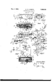
Nov. 1, 1932. G. w. OKEEFFE THERMORESPONSIVE DEVICE Filed Feb. 17, 1930 Patented Nov. 1, 1932 UNITED STAT-ES- PATENT OFFICE GEORGE W. OKEEFFE, O1 HILTON, MASSACHUSETTS, ASSIGNOB TO CONDIT ELECTRICAL MANUFACTURING CORPORATION, 01 SOUTH BOSTON, MASSACHUSETTS, A CORPO- BATION OF MASSACHUSETTS THERKORESPONSIVE DEVICE Application filled February 17, 1930. Serial No. 428,-910.
This invention relates to thernio-responsive devices and especially to thermal relays of the comprising an electrically heated ex- "oansilole element that operates to control an electric (Biro I which usually is the control nilot s *rically operated circuit inter t element for nt is inovert ad currents r is or circuit, which is circuit interrupter.
s of the invention is the l relay of we nerein the ly into two sec ovides a super associated rrnally errpansible member e contact member associated on in which it projects from the castilt Tilt? resetting means tor ton- 'J tact member disposed outside the casing and also having the contact biasing means thereso for disposed largely externally of the casing.
A further object of the invent on is the pro-' vision of a thermo-responsive device having preferably a bimetallic thermo-re'sponsive member that has reflexed portions, and where- 35 in the heating element therefor is located between the reflexed portions and is in heat transferring relation with both portions.
A yet further object of the invention is the *ovision of thermal relay having a thery enpansible element and an electrical 3 l i located close]. acl= ltll l 1 l r b 1 O J it he expansible mem er, out is c etn callv isolated therefrom; and more specimcally to provide a relay oi the cartridge type 43 having an expansible member comprising a strip which is bent baclrnpon itseli to member and having a longitudinal heatradiating grid portion disposed along and between the arms of said thermally expansible member.
A yet further object of the invention is the provision of a thermal relay including a U- shaped thermally expansible member having a spring urged movable contact member slidahly supported thereon and a heating eleinent having a rid for heating said erpansible element disposed the spaced arms or said expansihle element, the spring tor urging said movable contact being located externally of said U-shaped member.
A still further object of the invention is generally to improve the construction and operation of thermal relays.
l is a side elevation of a thermal relay embodying the invention.
Fig. 2 is an end elevation oil the relay the supporting base therefor.
Fin". 3 is a longitudinal sectional elevation d of t e relay along line 3-3 of Fig. 1.
Big. l is a longitudinal sectional view of the relay talren along the line of division of the two casing sections.
if 5 is a detail showing the ll-shaped ex- I l I patella member, the movable contact men ber carried thereby and the resetting means for the movable contact member.
Fig. 6 is a perspective view of the heating element.
Fig. 7 is a perspective view of the thermally expansible element.
Figs. 8 and 9 are perspective views of the two casing sections.
Fi 10 1s amodified form of relay adapted for automatically resetting when it has operated.
Fig. ll is a single phase wiring diagram illustrating the manner of associating the re- I v tn' ["M m l l wtll nit lltlll llll electric switch.
The relay here shown includes a generally tubular enclosing casing of the so-called cartridge type consisting of two complemental insulating sections 10 and12 which en the switch again completes the auxiliary circuit through the protective relay. 1
The modified form of thermal relay illustrated in Fig. is essentially the same as that above described except that it lacks the movable contact plate 38 and the resettin means therefor and is arranged automatica ly to re-establish the auxiliary circuit after the relay has operated. To this end, the upper leg 32 of the thermally expansible element extends beneath the fixed contact member of the upper casing section, and is provided with a contact member 118 which co operates with the fixed contact member 50. As the thermally expansible element becomes heated, the leg 32 thereof is adapted to flex downwardly and away from the contact member to break the auxiliary circuit. When the thermally expansible element has become sufiiciently cool it will flex in the opposite direction and will again make contact with the fixed contact member 50.
Some of the features of the relay herein described are described and claimed in my copending application, Serial Np. 364,149, filed May 18, 1929.
- Various modifications may be made in the construction and arrangement of the parts without departing from the scope of the invention.
I claim:
1. A thermal relay including an insulating enclosing casing having end terminals and a pair of intermediate terminals, a U- shaped thermally expansible element having spaced parallel legs normally connecting said intermediate terminals, a heating element 1 electrically connecting said end terminals and said heating element having a grid portion extended laterally therefrom an disposed between the arms ofsaid U-shaped expansible element.
2. A thermal relay including an insulating enclosin casing having end terminal members an intermediate terminal members, a
U-shaped thermallyexpansible element normally connecting electrically the intermediate terminal members, a heating element for 50 said expansible element electricall connecting the end terminal members an disposed alongside and closely adjacent said expansible element, said heating element having an angularly related grid portion which is disposed expansible element.
3. A thermal relay including an insulating enclosing casing having end terminal members and intermediate terminal members, a U-shaped thermally expansible element normally connecting electrically the intermediate terminal members, a heating element for said expansible element electrically connecting the end terminal members and disposed alongside and closely adjacent said expansible between the parallel arms of said U-shaped element, said heating element having an angularly related grid portion which is disposed between the parallel arms of said U-sha d expansible element, and insulating means isposed between the grid portion of said heatmg element and the inner surface of said U-shaped expansible element.
4. A thermal relay including an insulating enclosing casing, ferrules comprising line terminals of the relay carried by the ends thereof, opposed terminal studs extended through opposite walls of'said casin comprising auxiliary circuit terminals, a "-shaped thermally expansible element having one end there thermal relay including an insulating I enclosing casing having end ferrules comprising hne terminal members, and auxiliary terminals located intermediate said lineterminals on opposite sides of said casing and electrically insulated from said line terminals by said casing, a U-shaped thermally expansible element having one leg thereof electrically connected at one end with one of said intermediate terminal members and having the similar end of its other leg normally electrilocated alongside sald expansible element, 011
11 connected with the other of said intermediate terminal members, a heating element for said thermally expansible element including a strip of resistance material electrically connected between said end ferrules and located alongside said U-shaped expansible member, said heating element having a struck-but rid portion which extends longitudinally t ereof and which is disposed in alignment with and between the U-shaped legs of said expansible'element.
6. A thermal relay including an insulatingsenclosing casing having main end termina and oppositely disposed auxiliary terminals located between said end terminals and insulated therefrom, a thermally expansible element including a U-shaped bimetallic strip having flat parallel top and bottom legs, a heating element comprising a strip of resistance material located alongside said U-shaped expansible element and connected electrically between said end terminal members; s id heating element having a flat grid portl n laterally extended therefrom and disposed between and parallel with the flat legs of said thermally expansible element.
7. A thermal relay including an insulatat its end with v I mem rs, a heatin ing enclosing casing having end terminal members comprising the main line terminals of the relay, and oppositely disposed intermediate terminal members comprising auxiliary'circuit terminals of the relay, a U-shaped thermally expansible element having flat parallel legs one end of which element is fixedly electrically connected with one of said intermediate terminal members and the other and free end of which is detachably electrically connected with said other intermediate terminal member, a heating element for heating said expansible element electrically connected between said end terminals comprising a strip of resistance material disposed alongside said expansible member and in a plane normal to the fiat legs thereof, said heating element having a laterally extended grid portion which is disposed between and parallel with the flat legs of said thermally expansible element.
8. In a thermal relay, an enclosing casing, separable contact members located therein, means including a U-shaped thermally expansible element arranged to control the enga ement and separation of said contact element having a grid disposed between t e U-shaped legs of sa1d expansible element, and means including a resetting member located externally of said casing to effect the reenga ement of said contact members after they ave separated.
9. In a thermal relay, an enclosing casing, separable contact members located therein, means including a U-shaped thermally expansible element arranged to control the engagement and separation of said contact members, a heating element disposed alongside and closely adpcent said expansible element and having a grid rtion extended laterally therefrom and t: u;- between the legsof said U-shaped expansible element, and means includi a resetting member which is located externa y of said casing arranged to efiect the resetting of the contact members after they have operated. L i
10. In a thermal relay, an enclosing casing, separable contact members located therein, means including a U-shaped thermally -'I expansible element arranged to control the laterally therefrom and engagement and separation of said contact members, a heating element di osed alongside and closely adjacent sai expansible element and having a grid rtion extended isposed between the legs of said U-shaped expansible element,
and means including a resetting memberwhich is located externally of said casing arranged to efiect-the resetting of the contact members after they have operated and means normally biasing said resettin member into a contact separated position t ereof.
.11. In a thermal relay, an enclosing casing, a fixed contact member located in said casing, a U-shaped thermally expans'ible eleerated, and a heating element disposed along-' side said expansible element and having a grid portion thereof located between and parallel with the flat legs of said expansible element. '3
12. In a thermal relay, an enclosing casing, separable contact members located therein, means including a U-shaped thermally expansible member arranged to control the engagement and separation of said contact members, and a heating element including a fiat strip of resistance material having a longitu nal struck-out portion along one side thereof which is angularly-related to the plane of said strip and having a longitudinal cut away portions along the opposite side thereof which is shorter than said struckout portion, said struck-out portion adapted to lie between the spaced parallel legs of said U-shaped e ansible element.
13. In a t ermal relay, the combination of an enclosing casing, a fixed contact member carried thereby, a U-shaped thermally expansible member having a support at one end of said casing and having a contact member at its other end which is movable into and out of engagement with said fixed contact member, said movable contact member having an extension which is located externally of said casing when said contact members are separated, means including a resetting mem.- ber carried by said extension externall of said casi and a compression spring aving one end in engagement with said resetting member and its other and opposite end in engagement with said expansibleelement and constantly biasing said movable contacts for disengagement from said fixed contact. i
14. In a thermal relay, the combination of spring having one end in engagement with.
ICC
said resetting member and its other and opposite end in engagement with said expansible element andconstantly biasing said movable contact for disengagement from said fixed contact, and means including a stud fixed to said thermally expansible member and slidably extended into a recess in said resetting member, for retaining said spring n position. 15. In a thermo-responsive device, the combination of a flat bimetallic thermallyexpansible strip having a pair of spaced thermally-expansible sections disposed in generally parallel" relation with their fiat faces I .confrontingeach other and connected and spaced by anintermediate refie'xed portion, and a heater element therefor comprising a flat strip of resistance material which is disposed perpendicularly to said flat bimetallic strip and is located beside the similar edges of said expansible sections and extends lengthwise of said sections and has an int?- mediate heater section that is refiexed at right angles to said heater strip and is located between and extends longitudinally of said expansible sections and confronts the fiat faces of both of said sections.
In-testimony whereof, I have signed my name to this s ecification. IEORGE W. OKEEFFE.
Priority Applications (1)
| Application Number | Priority Date | Filing Date | Title |
|---|---|---|---|
| US428910A US1886355A (en) | 1930-02-17 | 1930-02-17 | Thermoresponsive device |
Applications Claiming Priority (1)
| Application Number | Priority Date | Filing Date | Title |
|---|---|---|---|
| US428910A US1886355A (en) | 1930-02-17 | 1930-02-17 | Thermoresponsive device |
Publications (1)
| Publication Number | Publication Date |
|---|---|
| US1886355A true US1886355A (en) | 1932-11-01 |
Family
ID=23700927
Family Applications (1)
| Application Number | Title | Priority Date | Filing Date |
|---|---|---|---|
| US428910A Expired - Lifetime US1886355A (en) | 1930-02-17 | 1930-02-17 | Thermoresponsive device |
Country Status (1)
| Country | Link |
|---|---|
| US (1) | US1886355A (en) |
Cited By (1)
| Publication number | Priority date | Publication date | Assignee | Title |
|---|---|---|---|---|
| US2520906A (en) * | 1946-06-22 | 1950-09-05 | Photoswitch Inc | Thermal microswitch |
-
1930
- 1930-02-17 US US428910A patent/US1886355A/en not_active Expired - Lifetime
Cited By (1)
| Publication number | Priority date | Publication date | Assignee | Title |
|---|---|---|---|---|
| US2520906A (en) * | 1946-06-22 | 1950-09-05 | Photoswitch Inc | Thermal microswitch |
Similar Documents
| Publication | Publication Date | Title |
|---|---|---|
| US2379602A (en) | Electrical apparatus | |
| US3031551A (en) | Electrical switch structures | |
| US1886355A (en) | Thermoresponsive device | |
| US1839935A (en) | Electric thermostat | |
| US3146378A (en) | Thermal relays | |
| US2302399A (en) | Thermal relay | |
| US3284597A (en) | Electrical control device of the thermal delay type | |
| US1652527A (en) | Protective device | |
| US3423712A (en) | Thermal protective device having rapid response to sudden high overloads and delayed response to moderate overloads | |
| US2094386A (en) | Motor protective device | |
| US3213239A (en) | Thermal time delay relay for switching and protecting start and phase windings of motors | |
| US3417228A (en) | Overload control for electric heater elements | |
| US1899558A (en) | Thermal responsive device | |
| GB474149A (en) | Improvements in or relating to electric motor controllers | |
| GB439242A (en) | Improvements in, or relating to, release mechanism for electrical switchgear | |
| US3207875A (en) | Thermal time delay relay for switching and protecting start and phase windings of motors | |
| US3202786A (en) | Low capacity, low current thermal time delay relay | |
| US2086755A (en) | Control device | |
| US3242292A (en) | Motor protector having sub-assembled heater and actuator | |
| US1886354A (en) | Thermal relay | |
| US2651696A (en) | Thermal overload switch | |
| US2234700A (en) | Control device | |
| US1910494A (en) | Thermal relay | |
| US2647188A (en) | Electrical switch contact means | |
| US2230713A (en) | Circuit breaker |