US1869375A - Dispensing apparatus - Google Patents
Dispensing apparatus Download PDFInfo
- Publication number
- US1869375A US1869375A US398310A US39831029A US1869375A US 1869375 A US1869375 A US 1869375A US 398310 A US398310 A US 398310A US 39831029 A US39831029 A US 39831029A US 1869375 A US1869375 A US 1869375A
- Authority
- US
- United States
- Prior art keywords
- valve
- air
- piston
- cylinder
- pipe
- Prior art date
- Legal status (The legal status is an assumption and is not a legal conclusion. Google has not performed a legal analysis and makes no representation as to the accuracy of the status listed.)
- Expired - Lifetime
Links
Images

Classifications
-
- B—PERFORMING OPERATIONS; TRANSPORTING
- B67—OPENING, CLOSING OR CLEANING BOTTLES, JARS OR SIMILAR CONTAINERS; LIQUID HANDLING
- B67D—DISPENSING, DELIVERING OR TRANSFERRING LIQUIDS, NOT OTHERWISE PROVIDED FOR
- B67D7/00—Apparatus or devices for transferring liquids from bulk storage containers or reservoirs into vehicles or into portable containers, e.g. for retail sale purposes
- B67D7/06—Details or accessories
- B67D7/08—Arrangements of devices for controlling, indicating, metering or registering quantity or price of liquid transferred
- B67D7/16—Arrangements of liquid meters
- B67D7/163—Arrangements of liquid meters of fixed measuring chamber type
Definitions
- This invention pertains to liquid dispensing apparatus and more particularly to fluid y control mechanism for filling the measuring container of liquid dispensing devices.
- the visible type of liquid dispensing apparatus in general includes an elevated container supported on a standard or casing, said container having a fill pipe through which the liquid is supplied thereto from a suitable pump, an Overow pipe terminatin at its upper end within the container at t e level for maximum capacity, and a service nozzle connected to the bottom ofthe elevated container and through which the customer is served with any desired quantity of liquid.
- the other type includes in general a flow meter, andv a pump for supplying liquid to the meter from which it is delivered through a hose connection after measuring by theconstant escape ofthe air and-the consequent passage of water of condensation through the valve in time creating rust and spoiling the perfect seating and operation of the valve.
- Another object of the invention is to provide liquid dispensing apparatus wherein the supply of air is controlled for effectively controlling operation ofthe apparatus.
- a further object - is to provide liquid dispensing apparatus which is so constructed A that flow of air from the compressor line may be sopped to prevent any air from being quirements of manufacture and service.
- the invention may consist of certain novel features of Vconstruction and operation, as will be more fully described and vparticula'ly pointed out in the specication, drawings and claims appended hereto.
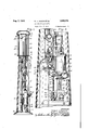
- Figure 1 is a sectional elevation through the dispensing apparatus
- Figure 2 is a fragmentary enlarged sectional elevaton through a portion of the dispensing apparatus shown in Figure 1, the same being taken substantially at right angles to Figure 1;
- Figure 3 is a side elevation of a portion of the valve mechanism and associated parts
- Figure 4 is a sectional elevation of the valve mechanism illustrated in Figure 3, the same beingtaken substantially in the plane as indicated by the line 4 4 of Figure 3;
- Figure 5 is a sectional top plan view of the valve mechanism illustrated in Figures 3 and 4, the same' beingtaken substantially inthe plane as indicated by the line 5--5 of Figure 4;
- Figure 6 is anenlarged perspective elevation of vthe piston illustrated in Figure 4.
- the housing 10 forming the pedestal or casing of the apparatus is providedl with a bottom head 12, upon which is seated the glass cylinder container 14 which provides a measuring chamber for the gasoline or other fluid to be dispensed.
- the top head 16 is supported on the top of thecontainer 14, and a dome 18 for advertising or other purposes is attached to the top head 16.
- Tie rods ⁇ 20 are disposed between the upper and lower heads for securely clamping the container 14 between cork gaskets 22 disposed between .the heads whereby there will be no leakager of the liquid or its vapor from the chamber and al1- Vforeign matter is kept out of said chamber.
- tie rodsv 24 are provided within the casing and are secured to the lower head and suitable foot portion 26 for completlng the unitary assembly.
- Gasoline or other liquid to ⁇ be dispensed is supplied from a suitable source of supply (not shown) to Athe measuring chamber through a fill pipe 28 by a pump 30, which pump is shown' as operated by means of the air 'cylinder 32 through the usual plungeror piston rod (not shown), it being understood that said piston rod extends through the stuing box 34 provided in cylinder lhead 36,
- the ioat trip rod 74 falls back of a notch 76 provided on the rod 78.
- the rod 78 is forced down by the lever 72 for holding the whistle valve stem 80 in depressed or open position whereby air is permitted to iiow through the pipe 66 to the inlet 68 of the valve 70.
- the .valve 70 is'provided with a piston 82 having oppositely facing cored passages or ports 84 and 86, said passages opening to passages or ports 88 and 90 provided completely around the piston.
- the casing of the valve is provided with a cored passage 92 which is adapted -to communicate with the port 84 of the piston 82 whereby air is supplied from the inlet 68 to the pipe 94, it being understood that said pipe opens to a port so located in the valve 70 that it is in communication with the port 88 when said port is in communication with passage 92..-
- the Ipipe 94 isl connected to the bottom of the pump cylinder 32 to supply air thereto whereby the piston therein is forced upward by the air supplied. Upward movement of the piston moves the coupling bar-46 upwardly until it contacts washer 96 provided Von the buiferspring 98, said spring being retained by the washer 100 which in turn is limitedin its upward movement by the nuts 102'adjustably provided'on the rod 104.
- the rod 104 extends upwardly through a pin 106 provided on the cranky or lever 108, said rod being held position with respect ⁇ to said pin by means of the nuts 110.-
- the lever is pivoted to the air valve bracket- 112 the bolt 114 on which is mounted. a tension spring116 for rigidly holding the lever 108l in a predetermined position,nthe spring 116 being controlled in tension position by means a slot 128 formed whereby said lever may be manually operated', if such is desired.
- Alignment of the port 90 and the passage 136 breaks communication between the port 90 and a cored passage 138 extending to the 'exhaust opening 140, and registering is caused between the port 90 and the cored passage ⁇ 142 which is also in communication with the exhaust opening 140.
- the measuring container is provided with Va float 156 disposed adjacent the top opening of the overflow pipe 158, the ioat' 156 being raised by the liquid and connected' to the floattrip rod 74 so that upward movement of the float raises the float trip rod to thereby pull the trip away from the notch 76, permitting the lever 72 to raise by sprin action on the whistle valve stem 80 to there y shut off the air and sto the pumping action of the pump 30.
- the oat may be limited in its downward movement by the stop 160 conveniently supported on the pipe 28, and the trip rod 74 is of course carried below the measuring chamber through a suitable conduit or casing 162l disposed therearound, the casing fiorming a convenient pivotal support for the oat.
- the ball 164 is provlded registering in an aperture 166 provided in the lever 122, the ball being disposed in a recess in thebracket arm. 168, which arm is held in position on the pin 170 by means of the pin 172 and the screw 174, said ball being spring pressed by the spring 176, the action of the spring being controlled by adjusting screw 178.
- the piston 82 is prevente from stopping on dead center, while simple manipulation of the lever 122 controls the position of the piston, should change be desired.
- the measuring chamber is provided with the usual overflow pipe 158 whereby the uppermost liquid level is controlled, it being understood that the measuring chamber here l shown measures from the top downwardly.
- the float 156 rests in its downward position 011 the stop 160.
- the lever 72 is depressed to a position where a portion of the float trip rod 74, secured to the oat and extending through the casing 162, falls back of thenotch 76 provided on the rod 78.
- the rod 78 is forced downwardly vby the lever 72, thereb depressing the whistle valve stem 80 where y air is permitted to flow from the source of supply through the relief valve 52,' pipe 54, whistle valve 56, which is in normal open position by virtue of the positioning of the'lever 60, pipe 58 to pipe 66.
- the air is then supplied to the valve casing 70 through the port 68, and assuming the piston to be in the position shown in Figure 4, air flows through the cored passage 92 to the port 88, thence through the pipe 94 tothe bottom of the air cylinder 32.
- the piston in the air cylinder is Vof course in downward position and is forced upwardly by ingress .of air to the bottom of the cylinder.
- the 'loat 156 When the proper level has been reached in the measuring chamber, the 'loat 156 will be moved upwardly, moving the float trip rod 7 4, releasing the levcr72, causing closing of the whistle valve 64, thereby cutting off supply of air to the piston. Any excess-supplied liquid will iow through the overflow pipe 158 back to the source of liquid supply.
- liquid dispensing apparatus the combination of a measuring container, a pump for pumping liquid to said measuringcontainer, an air cylinderhaving a piston therein for actuatingsaid pump, an a1r line connected to each end of said cylinder for actuating saidpiston, a valve for directing the flow' of air to each end of the cylinder after a predetermined movement of said piston, means in said air line for controlling the flow of air to said valve, and means cooperating with s'aid valve for preventing aci 130 l mined movement of said piston whereby said valve is fully operated.
- liquid dispensing apparatus theI combination of a ⁇ measuring container, a pump for pumping liquid to said measurmg container, an air .cylinder having a piston therein for actuating said pump, an air line connected to each end of said cylinder for actuating said piston, a valve for directing the flow of air to each end of the cylinder after apredetermined movement of said piston, means in said air line for controlling the low of air to said valve, means in said measuring container for operating said last named means when a predetermined amount of liquid is supplied to said container, and means n cooperating with said valve for preventmg connected to each end of said cylinder for vactuating said piston, a valve operated by said piston Jfor directing the flow of air to each end of the cylinder after a predetermined movement of said piston, a manually operated valve provided with means for latchingsaid valve in open position for controlling the flow of air to said iirst named valve, and means cooperating with said irst f named valve for preventing actuation of said
- valve is fully operated to prevent balancing thereof.
- liquid dispensing apparatus In liquid dispensing apparatus, the combination of a measuring container, a pump or'pumping liquidA to said measuring contalner, an air cylinder having a-piston therein for actuating said pump, an airline connected to each end of said cylinder Jfor actuating said piston, a valve for directing the flow of air to each end ofthe cylinder of liquid is supplied to said container, manafter a predetermined movement of said piston, means in said air line for controlling the iiow of air to said valve, means in said measuring container for operating said last named means when a predetermined amount ually operable means for simultaneouslyl operating said first named means to position to supply air to said valve ⁇ and to connect said first named means and sail second named means whereby said second named means is effective tooperate said iirst. named means, and means cooperating with said valve forpreventing actuation of said valve only after'a predetermined movement of said piston whereby said valveis fully' operated.
- liquid dispensing apparatus the combination of a measuring container, a pump for pumping liquid ⁇ to said measuring con ⁇ tainer, an air cylinder having a piston therein for actuating said pump, an air line connected to each end of said cylinder for actuating said piston, a valve for directing the vilow of air to each end ofthe cylinder after a predetermined movement of said piston, means in said air line for controlling the flow of air to said valve, means in said measuring container for operating said lastv named means when a predetermined amount of liquid is supplied to said container, a valve in said air line for rendering the apparatus inoperative, and means on the pump for manually operating said pump after said last named valve is rendered inoperative.
- liquid dispensing apparatus the combination of an elevated container from which liquid is dispensed, pumping means for supplying liquid to said container, means for operating said pumping means, an air line connected to said ysecond named means, a piston valve in said line for controlling operation o said second means, a whistle valve in said air line, manual means oroperating said whistle valve, latch means for maintaining said whistle valve open, control means for closing said whistle valve, automatic means coordinated with said pumping means for operating said piston valve whereby air is directed to the ends of said piston successively, a normally open whistle valve in said air line operable to closed position whereby the apparatus can be manually operated through the pump.
Landscapes
- Engineering & Computer Science (AREA)
- Physics & Mathematics (AREA)
- Mathematical Physics (AREA)
- Theoretical Computer Science (AREA)
- Mechanical Engineering (AREA)
- Loading And Unloading Of Fuel Tanks Or Ships (AREA)
Description
Aug'. 2, 1932. R. J. JAUcH E'r AL DISPENSING APPARATUS Filed Oct. 9, 1929 2 Sheets-Shelet 1 114/8 .1150`- 165 I I l JO 4" I- IN VENT ORS Aug..2, 1932. R. J. JAucH ET AL 1,859,375
I DISPENSING APPARATUS med oct. a, 192s y z sheds-sheet Fly. a. Fig. 4.
TTI I 'g l 16g, i [2Q l 170- 116 f f/o vme f 106 F19. 6. "Z y j Il@ 0m y INVENToRs.- Mbs-fi JJzzc/za Patented Aug. 2, 1932 UNrruDL STATES- yMJIENT OFFICE ROBERT J. JAUOII ANDIIARRY I.. MITCHELL, OE FORT WAYNE, INDIANA, As'sIGNORs To WAYNE COMPANY, OE FORT WAYNE, INDIANA, A CORPORATION or INDIANA DISPENSING APPARATUS Application led October 9, 1929. Serial No. 398,310.
This invention pertains to liquid dispensing apparatus and more particularly to fluid y control mechanism for filling the measuring container of liquid dispensing devices.
There are a number of liquid dispensing.
devices now being sold which may generally be classified in two classes-one: the visible type, and two: the meter type. The visible type of liquid dispensing apparatus in general includes an elevated container supported on a standard or casing, said container having a fill pipe through which the liquid is supplied thereto from a suitable pump, an Overow pipe terminatin at its upper end within the container at t e level for maximum capacity, and a service nozzle connected to the bottom ofthe elevated container and through which the customer is served with any desired quantity of liquid.
The other type includes in general a flow meter, andv a pump for supplying liquid to the meter from which it is delivered through a hose connection after measuring by theconstant escape ofthe air and-the consequent passage of water of condensation through the valve in time creating rust and spoiling the perfect seating and operation of the valve.
It is therefore an object of this invention to provide liquid dispensin apparatus wherein the ordinary leakage 0I air in pipes with joints of the device will not in any way injure or prevent the functioning of the automatic air valve.
Another object of the invention is to provide liquid dispensing apparatus wherein the supply of air is controlled for effectively controlling operation ofthe apparatus.
A further object -is to provide liquid dispensing apparatus which is so constructed A that flow of air from the compressor line may be sopped to prevent any air from being quirements of manufacture and service.
With these and various other objects in view, the invention may consist of certain novel features of Vconstruction and operation, as will be more fully described and vparticula'ly pointed out in the specication, drawings and claims appended hereto.
In the drawings, which illustrate -an embodiment of the device and wherein like reference characters are used to designate like parts-- f Figure 1 is a sectional elevation through the dispensing apparatus;
Figure 2 is a fragmentary enlarged sectional elevaton through a portion of the dispensing apparatus shown in Figure 1, the same being taken substantially at right angles toFigure 1;
Figure 3 is a side elevation of a portion of the valve mechanism and associated parts;
Figure 4 is a sectional elevation of the valve mechanism illustrated in Figure 3, the same beingtaken substantially in the plane as indicated by the line 4 4 of Figure 3;
Figure 5 is a sectional top plan view of the valve mechanism illustrated in Figures 3 and 4, the same' beingtaken substantially inthe plane as indicated by the line 5--5 of Figure 4; and
Figure 6 is anenlarged perspective elevation of vthe piston illustrated in Figure 4.
In the embodiment ofthe device illustrated, the housing 10 forming the pedestal or casing of the apparatus is providedl with a bottom head 12, upon which is seated the glass cylinder container 14 which provides a measuring chamber for the gasoline or other fluid to be dispensed. The top head 16 is supported on the top of thecontainer 14, and a dome 18 for advertising or other purposes is attached to the top head 16. Tie rods`20 are disposed between the upper and lower heads for securely clamping the container 14 between cork gaskets 22 disposed between .the heads whereby there will be no leakager of the liquid or its vapor from the chamber and al1- Vforeign matter is kept out of said chamber.
mo v- Other tie rodsv 24 are provided within the casing and are secured to the lower head and suitable foot portion 26 for completlng the unitary assembly. l
Gasoline or other liquid to `be dispensed is supplied from a suitable source of supply (not shown) to Athe measuring chamber through a fill pipe 28 by a pump 30, which pump is shown' as operated by means of the air 'cylinder 32 through the usual plungeror piston rod (not shown), it being understood that said piston rod extends through the stuing box 34 provided in cylinder lhead 36,
f said head being secured through vthe tie rods relief valve 52, pipe 54, whistle valve 56 and pipe 58. The' whistle valve 56 is held open y means of a lever 60 lwhich islocked in valve-open position by means of thescrew 62. The pipe 58 is connected -to the whistle valve 64, the valve 64 being connected through the pipe 66 to the inlet 68 of the air valve 70. The whistle valve 64is held open to permit the passage of air therethrough by depressing the lever 72 to a position where.
the ioat trip rod 74 falls back of a notch 76 provided on the rod 78. The rod 78 is forced down by the lever 72 for holding the whistle valve stem 80 in depressed or open position whereby air is permitted to iiow through the pipe 66 to the inlet 68 of the valve 70. The .valve 70 is'provided with a piston 82 having oppositely facing cored passages or ports 84 and 86, said passages opening to passages or ports 88 and 90 provided completely around the piston. The casing of the valve is provided with a cored passage 92 which is adapted -to communicate with the port 84 of the piston 82 whereby air is supplied from the inlet 68 to the pipe 94, it being understood that said pipe opens to a port so located in the valve 70 that it is in communication with the port 88 when said port is in communication with passage 92..-
The Ipipe 94 isl connected to the bottom of the pump cylinder 32 to supply air thereto whereby the piston therein is forced upward by the air supplied. Upward movement of the piston moves the coupling bar-46 upwardly until it contacts washer 96 provided Von the buiferspring 98, said spring being retained by the washer 100 which in turn is limitedin its upward movement by the nuts 102'adjustably provided'on the rod 104. The rod 104 extends upwardly through a pin 106 provided on the cranky or lever 108, said rod being held position with respect` to said pin by means of the nuts 110.- The lever is pivoted to the air valve bracket- 112 the bolt 114 on which is mounted. a tension spring116 for rigidly holding the lever 108l in a predetermined position,nthe spring 116 being controlled in tension position by means a slot 128 formed whereby said lever may be manually operated', if such is desired.
-Upward movement'of the lever 108 tends to pull down onthe 'inner end of the lever 122 due to the pivotal connection 130 between the lever and the bracket 112. Movement of lthe outer end of the lever 122 \in one direction moves piston rod 132 in the opposite direction, as such piston rod is pivoted at 134 to the inner end of said lever through a suitable loose connection. Movement of the piston rod 132 downwardly lowers the piston 82 so thatvthe port 90 is in a line with a cored passage 136 which is in communica tion with the inlet 68. Alignment of the port 90 and the passage 136 breaks communication between the port 90 and a cored passage 138 extending to the 'exhaust opening 140, and registering is caused between the port 90 and the cored passage`142 which is also in communication with the exhaust opening 140.
This position of the piston allows'the airto iiow through the cored passage 136 to the port 90, through port 86, and thence. out through pipe 1.44 which communicates with the upper part of the cylinder'32, that is, introducing air above the piston forcing the plunger downwardly. The air under the plunger is then free to exhaust through the pipe 94 to port 88, through cored passage 142 and to exhaust opening 140, and thence outwardly. through exhaust pipe 146. In
like manner the air above the piston, from the cylinder 32 is free to exhaust when the coupling bar 46 is lowered against the washer 148 and spring 150,*which rests on-the washer 152 retained on the rod 104 by means ofthe nuts 154. 4The travel then of the coupling or cross-head is limited by the nuts 154'v and 102, thus controlling the travel of the lever 122 and therefore the piston 82. When the piston 82 is in its up position, that is, when the lever 122 is depressed, the port 90 is in line with the cored passage 138, allowing the air to pass out through the exhaust opening 140 through the cored passage 138, ex`
haust opening and out through the exhaust pipe 146. A l
The measuring container is provided with Va float 156 disposed adjacent the top opening of the overflow pipe 158, the ioat' 156 being raised by the liquid and connected' to the floattrip rod 74 so that upward movement of the float raises the float trip rod to thereby pull the trip away from the notch 76, permitting the lever 72 to raise by sprin action on the whistle valve stem 80 to there y shut off the air and sto the pumping action of the pump 30. The oat may be limited in its downward movement by the stop 160 conveniently supported on the pipe 28, and the trip rod 74 is of course carried below the measuring chamber through a suitable conduit or casing 162l disposed therearound, the casing fiorming a convenient pivotal support for the oat.
In order to have a positive action of the piston 82, that is, in order for enough pressure to build up to shift the piston to revent dead centering, the ball 164 is provlded registering in an aperture 166 provided in the lever 122, the ball being disposed in a recess in thebracket arm. 168, which arm is held in position on the pin 170 by means of the pin 172 and the screw 174, said ball being spring pressed by the spring 176, the action of the spring being controlled by adjusting screw 178. B this construction, the piston 82 is prevente from stopping on dead center, while simple manipulation of the lever 122 controls the position of the piston, should change be desired.
The measuring chamber is provided with the usual overflow pipe 158 whereby the uppermost liquid level is controlled, it being understood that the measuring chamber here l shown measures from the top downwardly. In operation of the device, assuming that the measuring chamber is empty, the float 156 rests in its downward position 011 the stop 160. The lever 72 is depressed to a position where a portion of the float trip rod 74, secured to the oat and extending through the casing 162, falls back of thenotch 76 provided on the rod 78. The rod 78 is forced downwardly vby the lever 72, thereb depressing the whistle valve stem 80 where y air is permitted to flow from the source of supply through the relief valve 52,' pipe 54, whistle valve 56, which is in normal open position by virtue of the positioning of the'lever 60, pipe 58 to pipe 66. The air is then supplied to the valve casing 70 through the port 68, and assuming the piston to be in the position shown in Figure 4, air flows through the cored passage 92 to the port 88, thence through the pipe 94 tothe bottom of the air cylinder 32. The piston in the air cylinder is Vof course in downward position and is forced upwardly by ingress .of air to the bottom of the cylinder. As the pistonmoves upwardly, the coupling or crosshead 46 is moved-upwardly by the piston thereof,ca`1`1sing the crosshead to contact the washer 96 to contract the spring 98 against the washer 100. f When the piston is adjacent the top'f the 'cylinder 32,"enough force will be built up in the spring 98 to move the rod 104 upwardly, *55 thereby moving the pin 124 downwardly,
tuation of saidvalve only after a .predetercausing the upper portion of the lever 122 to move upwardly untilthe ball 164 snaps in the lower opening 166. Upward movement of thel outer end of the lever 122, of course, causes the piston 82 to move downwardly, shutting olf supply of air to the pipe 94 and. causing registering between the cored passage 136 and the port 90, which port then causes supply of compressed-air t'. the pipe 144 which is in communication with the upper portion of the cylinder 32. The port 88 will have registered with the cored passage 142 which is in communication with the ex-l haust port 140. Supply of compressed airto the upper portion of the cylinder 32`c'auses the piston to travel downwardly, exhausting the air thereunder through the pipe 94, port 88, cored passage 142, exhaust port 140 and pipe 146. The piston will travel downwardly until the crosshead causes compression of the spring 150, which will operate the rod 104 downwardly, thereby depressing the lever 122. Of course upward and downward move- \ment of the piston in the cylinder 32 operates the pump to supply liquid to the measuring chamber through the fill pipe 28.
When the proper level has been reached in the measuring chamber, the 'loat 156 will be moved upwardly, moving the float trip rod 7 4, releasing the levcr72, causing closing of the whistle valve 64, thereby cutting off supply of air to the piston. Any excess-supplied liquid will iow through the overflow pipe 158 back to the source of liquid supply.
It will be appreciated that w1th the construction described, that the leakage of the air in any part will not aect the operation of the device, and it will be appreciated that should any-portion of the automatic control become inoperative, hand operation of the pump 30 through the fitting 42 can take place to ll the measuring chamber in the usual manner.
It is to be understood that we do not wish to' be limited by the exact embodiment of the device shown, -which is merely by way of illustrationv and not limitation, as various and other forms of the device will of course be apparent to those skilled in the art without departing from the spirit of theinvention or the scope of the claims.
We claim: I
1. In liquid dispensing apparatus, the combination of a measuring container, a pump for pumping liquid to said measuringcontainer, an air cylinderhaving a piston therein for actuatingsaid pump, an a1r line connected to each end of said cylinder for actuating saidpiston, a valve for directing the flow' of air to each end of the cylinder after a predetermined movement of said piston, means in said air line for controlling the flow of air to said valve, and means cooperating with s'aid valve for preventing aci 130 l mined movement of said piston whereby said valve is fully operated.
2. In liquid dispensing apparatus, theI combination of a` measuring container, a pump for pumping liquid to said measurmg container, an air .cylinder having a piston therein for actuating said pump, an air line connected to each end of said cylinder for actuating said piston, a valve for directing the flow of air to each end of the cylinder after apredetermined movement of said piston, means in said air line for controlling the low of air to said valve, means in said measuring container for operating said last named means when a predetermined amount of liquid is supplied to said container, and means n cooperating with said valve for preventmg connected to each end of said cylinder for vactuating said piston, a valve operated by said piston Jfor directing the flow of air to each end of the cylinder after a predetermined movement of said piston, a manually operated valve provided with means for latchingsaid valve in open position for controlling the flow of air to said iirst named valve, and means cooperating with said irst f named valve for preventing actuation of said irstnamed valve only after a predetermined movement of said piston whereby said first.
named valve is fully operated to prevent balancing thereof.
'4. In liquid dispensing apparatus, the combination of a measuring container, a pump or'pumping liquidA to said measuring contalner, an air cylinder having a-piston therein for actuating said pump, an airline connected to each end of said cylinder Jfor actuating said piston, a valve for directing the flow of air to each end ofthe cylinder of liquid is supplied to said container, manafter a predetermined movement of said piston, means in said air line for controlling the iiow of air to said valve, means in said measuring container for operating said last named means when a predetermined amount ually operable means for simultaneouslyl operating said first named means to position to supply air to said valve `and to connect said first named means and sail second named means whereby said second named means is effective tooperate said iirst. named means, and means cooperating with said valve forpreventing actuation of said valve only after'a predetermined movement of said piston whereby said valveis fully' operated.
. 5. In liquid dispensing apparatus, the combination of a measuring container, a pump for pumping liquid `to said measuring con` tainer, an air cylinder having a piston therein for actuating said pump, an air line connected to each end of said cylinder for actuating said piston, a valve for directing the vilow of air to each end ofthe cylinder after a predetermined movement of said piston, means in said air line for controlling the flow of air to said valve, means in said measuring container for operating said lastv named means when a predetermined amount of liquid is supplied to said container, a valve in said air line for rendering the apparatus inoperative, and means on the pump for manually operating said pump after said last named valve is rendered inoperative.
' 6. In liquid dispensing apparatus, the combination of an elevated container from which liquid is dispensed, pumping means for supplying liquid to said container, means for operating said pumping means, an air line connected to said ysecond named means, a piston valve in said line for controlling operation o said second means, a whistle valve in said air line, manual means oroperating said whistle valve, latch means for maintaining said whistle valve open, control means for closing said whistle valve, automatic means coordinated with said pumping means for operating said piston valve whereby air is directed to the ends of said piston successively, a normally open whistle valve in said air line operable to closed position whereby the apparatus can be manually operated through the pump.
combination of a pump Jor pumping liquid to be dispensed, an air cylinder having a v pistonv therein for actuating said pump, an airline connected to each end of said cylinder for actuating said piston, a valve for directing the flow of air to each end of said cylinder after a predetermined movement of said piston, means in said air line for controlling flow of'air to said valve, and means vcoo ratino' with said valve for reventind h actuation of said valve only after a predetermined movement of said piston whereby said valve is fully. operated.Y p
Signed at Fort Wayne, Indiana, this fourth day of October, 1929. Y
v ROBERT J. JAUCH.
HARRY L. MITCHELL.
7. `In liquid dispensing y apparatus, the
llo
Priority Applications (1)
| Application Number | Priority Date | Filing Date | Title |
|---|---|---|---|
| US398310A US1869375A (en) | 1929-10-09 | 1929-10-09 | Dispensing apparatus |
Applications Claiming Priority (1)
| Application Number | Priority Date | Filing Date | Title |
|---|---|---|---|
| US398310A US1869375A (en) | 1929-10-09 | 1929-10-09 | Dispensing apparatus |
Publications (1)
| Publication Number | Publication Date |
|---|---|
| US1869375A true US1869375A (en) | 1932-08-02 |
Family
ID=23574895
Family Applications (1)
| Application Number | Title | Priority Date | Filing Date |
|---|---|---|---|
| US398310A Expired - Lifetime US1869375A (en) | 1929-10-09 | 1929-10-09 | Dispensing apparatus |
Country Status (1)
| Country | Link |
|---|---|
| US (1) | US1869375A (en) |
-
1929
- 1929-10-09 US US398310A patent/US1869375A/en not_active Expired - Lifetime
Similar Documents
| Publication | Publication Date | Title |
|---|---|---|
| US2211282A (en) | Liquid transferring apparatus | |
| US1550738A (en) | Filler spout | |
| US1869375A (en) | Dispensing apparatus | |
| US2222923A (en) | Fluid filling nozzle | |
| US2258637A (en) | Portable dispenser for lubricating oil | |
| US2302766A (en) | Hose nozzle | |
| US1780605A (en) | Automatic tank loader for fuel trucks | |
| US2083965A (en) | Compressed air operated liquid dispensing device | |
| US2093952A (en) | Siphon-breaking means for liquid metering systems | |
| US1390508A (en) | Oil-dispensing apparatus | |
| US1843674A (en) | Dispensing device | |
| US1282890A (en) | Liquid-dispensing devices. | |
| US1248818A (en) | Liquid-dispensing measure. | |
| US1855667A (en) | Liquid dispensing apparatus | |
| US2164789A (en) | Tank filling device | |
| US1684879A (en) | Apparatus for dispensing lubricating oil | |
| US1749161A (en) | Filling apparatus | |
| US1350517A (en) | Compressed-air device for handling gasolene | |
| US1471529A (en) | Apparatus for dispensing liquids | |
| US1654249A (en) | Beverage-dispensing apparatus | |
| US2870800A (en) | Automatic liquid delivery shut-off device | |
| US1413046A (en) | Totalizing meter | |
| US512587A (en) | Measuring-pump | |
| US1733423A (en) | Liquid-dispensing apparatus | |
| US1565794A (en) | Fluid-distributing system |