US1867775A - Expansion means for bell and spigot pipes - Google Patents
Expansion means for bell and spigot pipes Download PDFInfo
- Publication number
- US1867775A US1867775A US329925A US32992529A US1867775A US 1867775 A US1867775 A US 1867775A US 329925 A US329925 A US 329925A US 32992529 A US32992529 A US 32992529A US 1867775 A US1867775 A US 1867775A
- Authority
- US
- United States
- Prior art keywords
- pipe
- pipes
- bell
- expansion
- spigot
- Prior art date
- Legal status (The legal status is an assumption and is not a legal conclusion. Google has not performed a legal analysis and makes no representation as to the accuracy of the status listed.)
- Expired - Lifetime
Links
- 239000000463 material Substances 0.000 description 21
- 230000008602 contraction Effects 0.000 description 9
- 238000009428 plumbing Methods 0.000 description 8
- 238000010276 construction Methods 0.000 description 7
- 238000006073 displacement reaction Methods 0.000 description 5
- 238000012856 packing Methods 0.000 description 4
- 239000002184 metal Substances 0.000 description 3
- 229910052751 metal Inorganic materials 0.000 description 3
- 239000002689 soil Substances 0.000 description 3
- XLYOFNOQVPJJNP-UHFFFAOYSA-N water Substances O XLYOFNOQVPJJNP-UHFFFAOYSA-N 0.000 description 3
- IHPYMWDTONKSCO-UHFFFAOYSA-N 2,2'-piperazine-1,4-diylbisethanesulfonic acid Chemical compound OS(=O)(=O)CCN1CCN(CCS(O)(=O)=O)CC1 IHPYMWDTONKSCO-UHFFFAOYSA-N 0.000 description 2
- RWSOTUBLDIXVET-UHFFFAOYSA-N Dihydrogen sulfide Chemical compound S RWSOTUBLDIXVET-UHFFFAOYSA-N 0.000 description 2
- 239000007990 PIPES buffer Substances 0.000 description 2
- 238000005452 bending Methods 0.000 description 2
- 238000009435 building construction Methods 0.000 description 2
- 229910000037 hydrogen sulfide Inorganic materials 0.000 description 2
- 239000002699 waste material Substances 0.000 description 2
- 239000002351 wastewater Substances 0.000 description 2
- 229910001018 Cast iron Inorganic materials 0.000 description 1
- 238000004891 communication Methods 0.000 description 1
- 230000001066 destructive effect Effects 0.000 description 1
- 239000007789 gas Substances 0.000 description 1
- 239000004576 sand Substances 0.000 description 1
- 238000007789 sealing Methods 0.000 description 1
Images

Classifications
-
- F—MECHANICAL ENGINEERING; LIGHTING; HEATING; WEAPONS; BLASTING
- F16—ENGINEERING ELEMENTS AND UNITS; GENERAL MEASURES FOR PRODUCING AND MAINTAINING EFFECTIVE FUNCTIONING OF MACHINES OR INSTALLATIONS; THERMAL INSULATION IN GENERAL
- F16L—PIPES; JOINTS OR FITTINGS FOR PIPES; SUPPORTS FOR PIPES, CABLES OR PROTECTIVE TUBING; MEANS FOR THERMAL INSULATION IN GENERAL
- F16L13/00—Non-disconnectable pipe joints, e.g. soldered, adhesive, or caulked joints
- F16L13/12—Non-disconnectable pipe joints, e.g. soldered, adhesive, or caulked joints with a seal made of lead, caulked packing, or the like
- F16L13/122—Non-disconnectable pipe joints, e.g. soldered, adhesive, or caulked joints with a seal made of lead, caulked packing, or the like for male-female connections
Definitions
- This invention relates to an expansion means for bell and spigot pipes and particularly to an arrangement whereby the pipes are spaced axially within the bells or hubs of the pipes during erection so that when the pipes are put in service, expansion and contraction of the same will be axial withoutany buckling of the pipes and consequent breaking or damage of the caulking material.
- Pipe stacks which are used at the present time in connection with plumbing pipes and waste pipes for other purposes are supported in the completed building structure at a plurality of places in the length of the pipes so that when expansion and contraction of the pipes occur in service, especially pipes which convey hot and cold water, something must give.
- the expansion causes buckling of the pipes between the points of support with the result that the pipes are moved sideways out of true position and the caulking material broken or damaged to such an extent as to allow escape of sewer or other obnoxious gases.
- the caulking material is displaced from within the hell or hub of the pipe.
- An object of the present invention is to provide a joint construction for bell and spigot pipes and the like which is effective to prevent buckling of the pipes and damage to the caulking material.
- Another object of the invention is to provide a locking of the caulking material within the bells of the pipes.
- a further object of the invention is to provide joints in hell and spigot pipe lines where'- in movement of the pipes under expansion and contraction is axial and not lateral and in which the caulking material is secured against bodily displacement.
- a still further object of the invention is to provide means for spacing pipe sections in a bell and spigot pipe line construction wherein movement due to expansion and contraction is restricted to movement axially and not laterally and in which damage to the caulking material is eliminated;
- Figure 1 is a side elevational view some: what fragmental in form of a soil and ventilating pipe construction for plumbing'fixtures, there being plumbing connections for three stories illustrated. v v
- FIG. 2 is a side elevational view somewhat fragmental in character of two pipe stacks embodying the present invention.
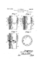
- Figure 3 is .a fragmental' sectional View through a bell and spigot pipe joint construction embodying this invention.
- the spigot pipe of Figure 3 is made without any external flange at the lower end of the pip e where the 1 same enters the bell of the next adj acentsection.
- Figure 4 is a view similar to Figure 3 showing an annular ring formed on the outer end of the spigot pipes. V V V
- Figure 5 is a view slmilar to Figure 3 showing the expansionring as beingformed' integrally with the bellpipe. V a,
- Figure 6 is a section taken on line VIVI of Figure 4.
- Pipe stacks for plumbing fixtures are subjected to wide ranges of temperature variation due to the waste water from bath tubs, wash basins, lavatories, and the like, resulting in extreme expansion and contraction of the pipes in service.
- pipe stacks used for plumbing fixtures buckle at the joints under expansion causing the caulking material such as lead to loosen or crack and eventually creep upwardly out of the bells or hubs of the pipes allowing seepage of sewer gas or water to leak at these joints which leakages of course are highly unclesirable.
- This invention is directed to the provision of an expansion joint in a bell and spigot pipe lines wherein the spigot pipe is spaced axially from the shoulder of the bell during erection of the pipe line.
- the expansion means being such as to be movable out ofthe way of the supported spigot pipes when pipes expand in service.
- the invention contemplates the locking of the caulking material in the bellor hub'of the pipe to prevent bodily displacement of the caulking material. The invention therefore results in axial movement of the pipes in expansion and contraction without any lateral displacement of the same so that damage to the caulking material is eliminated.
- Figure 1 shows somewhat diagrammatically in form a soil pipe A made up of a plural ity of bell and spigot pipe sections 1 and 2 with the usual connector 3 at the various floor levels for connection with suitable plumbing fixtures.
- the ventilating stack B comprises a plurality of similar bell and spigot pipes 4 and 5 connected with branches 6 into the connectors 3 for ventilating the same as is standard 7 practice.
- Lateral soil pipes? are arranged in connection'with the connectors 3 for communication with bath tubs, wash basins, and the like.
- the connectors 3 are provided with the usual connection for toilets.
- Figure 2 discloses twopipe stacks, the one at the left comprising bell and spigot pipe sections 1 and 2 of cast iron or similar cast metal, while .the one at the right discloses a pipe 8 which is threaded at its upper end as at 9for threaded engagement with a fixture or .connector 10.
- Figure 4 is a section through a pipe joint comprising a cast metal pipe 1 and a cast metal pipe 2, the pipe 2 being referred to herein as the spigot pipe.
- the pipe 2 has an annular collar 11 passed about the lower end of the same for entering within the hell or hub 12 of the pipe 1.
- n expansion member shown in Figure 4 as comprising a ring 13 is placed within the hub 12 engaging the shoulder 14 of said hub.
- The. ring- '13. has a plurality of short inwardly or centrally directed'lugs or fingers 15 which lugs are notched at 16 for a pur pose to be hereinafter described.
- the lower end of the spigot pipe 2 rests on the extremities of the lugs 15 while the pipe'stack is being installed.
- the ring 13' therefore supbell 12 about the lower end of the spigot pipe 2.
- Other caulking material, such as lead 17 is then run into the upper end of the bell 12 sealingthe joints between the bell 12 and the spigot pipe 2.
- the inner surface of the upper portion of the bell 12 is provided as shown in Figure 4 with an annular ring 18 and an annular channel 19 so that the lead or other caulking material 17 run into the upper end of the bell will when cold be securely locked in thebell 12against bodily displacement.
- the strength of the fingers or lugs 15 of the expansion ring 13 is such as to support the various pipe sections in the stack during erection of the stack. It is understood that the pipe stack is temporarily supported in the building structure no matter of what the building structure is composed and when secured permanently in place, the stacks are fastened at various points in the length of the same in the building structure.
- An expansion member such as ring 13 spaces a spigot pipe 2 when the same is installed so that when expansion takes place, the spigot pipe 2 will move axially relatively to the bell pipe 1 bending or otherwise displacing the outer ends of the lugs 15 thus eliminating all lateral movement of the pipes.
- the caulking material 17 being locked with in the bell 12 in the manner before described will retain the caulking material against dis placement as thepipes 1 and 2 move relatively to each other under expansion and contraction so that at all times a leak tight joint is provided. 7
- Figure 3 shows they arrangement of the parts when the threaded pipe 8 is inserted in a bell pipe 1 or inserted in the upper end of one of the connectors 10 as in the latter instance an expansion member, such as ring 13 would'be utilized.
- Figure 5 shows the projections 20 cast integrally with a bell pipe 21.
- the projections 20 are notched at 22 similarly to projections 15 heretofore described so that when the pipes 21 and 8 move relatively to each other, the lugs 20 will be displaced to allow axial movement of the pipes without causing lateral and destructive movements of the same.
- the depth of the packing ring 13 and the arrangement of the integral fingers or lugs 20 is such as to allowmaximum axial movement between the pipes joined in the manner herein described and may be bent downwardly out of the path of movement of the spigot pipe or may be broken off and fall to the lower end of the pipe 10.
- the material of which the ring 13 is made may be of breakable or yieldable material for accomplishing the purposes intended.
- the pipe stacks are erected before being permanently fastened in. the structure, hence it is necessary to space the bell and spigot pipes as heretofore described when the stacks are erected as the caulking has to be done before the pipe stacks can be permanently fastened in place.
- expansion joints herein described are useful to take care of any settling of the building after construction, as every building no matter what its character, is subject to settling to some extent.
- the expansion member herein described allows proper spacing of the pipe forming the joint during the erection of the pipe stacks which expansion or spacing element is rendered inefiective after the pipes are put in service by the expansion of the pipes bending or breaking off the supporting lugs.
- The'packing material which may be employed for packing the spigot pipe in the bell of the bell pipe may consist of oakum 16 and caulked lead 17. Such a seal will allow longitudinal movement of the pipes.
- a pipe stack including bell and spigot pipe sections arranged end to end, means within a bell portion of a pipe for supporting the end of an adjacent pipe section in spaced relation within the bell, said means including a plurality of inwardly extending projections for underlying the end of the supported pipe, said projections being movable out of the way of the supported pipe by said sup-. ported pipe when the same is moved axially by expansion.
- a pipe stack comprising a plurality of pipe sections having bells at the upper ends of the sections, said bells receiving the other ends of the adjacent pipe sections, an expansion ring within a bell having centrally directed lugs for temporarilysupporting the adj acent pipe section in spaced relation within the bell, said lugs being breakable when said pipe section moves axially under expansion.
- An expansion joint for pipes comprising a bell mouthed socket, means within said bell mouthed socket for temporarily supporting a length of pipe,'said meansincluding a plurality of inwardly projecting lugs for underlying the supported pipe, said lugs being moved away from underneath said supported pipe by said supported pipe as the same moves axially with respe'ctto the bell mouthed socket under expansion, and permanent sealmg means in sand socket around said pipe arranged to allow longitudinal movement of said pipes, said sealing means being locked within said socket.
- An expansion joint for a pipe stack including'a socket, and a pipe, and a plurality of lugs integral with the socket extending towards the axis thereof for temporarily receiving and supporting the pipe therein and for spacing the same axially within the socket, said lugs being removable out of the path of the said pipe by the pipe itself when the same moves axially under expansion.
- An expansion joint for a pipe stack comprising a bell mouthed'pipe socket having an interior shoulder, a ring supported by said shoulder, said ring having a plurality. of lugs extending towards the center thereof for temporarily supporting thereon an upstanding pipe stack during construction, said lugs being movable out of the Way of the supported pipe when said pipes move relatively axially under expansion.
Landscapes
- Engineering & Computer Science (AREA)
- General Engineering & Computer Science (AREA)
- Mechanical Engineering (AREA)
- Joints Allowing Movement (AREA)
Description
y A. E. STRINGER 1,867,775
EXPANSION MEANS FOR BELL AND SPIGOT PIPES I Filed Jan. 2, 1929 2 Sheets-Sheet 1 ifllffrecl 557 6, er.
July 19, 1932-. A. E. STRINGER EXPANSION MEANS FOR BELL AND SPIGOT PIPES Filed Jan. 2, 1929 2 Sheets-Sheet 2 Patented July .19, 1932 UNITED srrs ALFRED E. s'rnINGEn, or cHIcAeo, I nrNoIs nxrANsIoN MEANS roe BELL AND srreor PIPES Application filed January 2, 1929. Serial No. 329,925.
This invention relates to an expansion means for bell and spigot pipes and particularly to an arrangement whereby the pipes are spaced axially within the bells or hubs of the pipes during erection so that when the pipes are put in service, expansion and contraction of the same will be axial withoutany buckling of the pipes and consequent breaking or damage of the caulking material.
Pipe stacks which are used at the present time in connection with plumbing pipes and waste pipes for other purposes are supported in the completed building structure at a plurality of places in the length of the pipes so that when expansion and contraction of the pipes occur in service, especially pipes which convey hot and cold water, something must give. Sometimes the expansion causes buckling of the pipes between the points of support with the result that the pipes are moved sideways out of true position and the caulking material broken or damaged to such an extent as to allow escape of sewer or other obnoxious gases. Sometimes also the caulking material is displaced from within the hell or hub of the pipe.
An object of the present invention is to provide a joint construction for bell and spigot pipes and the like which is effective to prevent buckling of the pipes and damage to the caulking material.
Another object of the invention is to provide a locking of the caulking material within the bells of the pipes.
A further object of the invention is to provide joints in hell and spigot pipe lines where'- in movement of the pipes under expansion and contraction is axial and not lateral and in which the caulking material is secured against bodily displacement.
A still further object of the invention is to provide means for spacing pipe sections in a bell and spigot pipe line construction wherein movement due to expansion and contraction is restricted to movement axially and not laterally and in which damage to the caulking material is eliminated; v
The above,.other. and further obj ectsof the invention will be apparent from the following description, accompanyingdrawings and appended claims. i V
An embodiment of the invention is illustrated in the accompanying drawings and the views thereof are as follows: w v
Figure 1 is a side elevational view some: what fragmental in form of a soil and ventilating pipe construction for plumbing'fixtures, there being plumbing connections for three stories illustrated. v v
Figure 2 is a side elevational view somewhat fragmental in character of two pipe stacks embodying the present invention.
Figure 3 is .a fragmental' sectional View through a bell and spigot pipe joint construction embodying this invention. The spigot pipe of Figure 3 is made without any external flange at the lower end of the pip e where the 1 same enters the bell of the next adj acentsection. Figure 4 is a view similar to Figure 3 showing an annular ring formed on the outer end of the spigot pipes. V V
Figure 5 is a view slmilar to Figure 3 showing the expansionring as beingformed' integrally with the bellpipe. V a,
Figure 6 is a section taken on line VIVI of Figure 4. j
As shown on the drawings This invention is especially useful in 0011',
nection with pipe stacks for plumbing fixtures used in building construction which stacks areconstructed sometimes in advance of the building construction and often times are supported temporarily at least until the permanent building structure is erected,
Pipe stacks for plumbing fixtures are subjected to wide ranges of temperature variation due to the waste water from bath tubs, wash basins, lavatories, and the like, resulting in extreme expansion and contraction of the pipes in service. Heretofore pipe stacks used for plumbing fixtures buckle at the joints under expansion causing the caulking material such as lead to loosen or crack and eventually creep upwardly out of the bells or hubs of the pipes allowing seepage of sewer gas or water to leak at these joints which leakages of course are highly unclesirable.
This invention is directed to the provision of an expansion joint in a bell and spigot pipe lines wherein the spigot pipe is spaced axially from the shoulder of the bell during erection of the pipe line. The expansion means being such as to be movable out ofthe way of the supported spigot pipes when pipes expand in service. Furthermore, the invention contemplates the locking of the caulking material in the bellor hub'of the pipe to prevent bodily displacement of the caulking material. The invention therefore results in axial movement of the pipes in expansion and contraction without any lateral displacement of the same so that damage to the caulking material is eliminated.
Figure 1 shows somewhat diagrammatically in form a soil pipe A made up of a plural ity of bell and spigot pipe sections 1 and 2 with the usual connector 3 at the various floor levels for connection with suitable plumbing fixtures. I
The ventilating stack B comprises a plurality of similar bell and spigot pipes 4 and 5 connected with branches 6 into the connectors 3 for ventilating the same as is standard 7 practice.
Lateral soil pipes? are arranged in connection'with the connectors 3 for communication with bath tubs, wash basins, and the like. The connectors 3 are provided with the usual connection for toilets.
Figure 2 discloses twopipe stacks, the one at the left comprising bell and spigot pipe sections 1 and 2 of cast iron or similar cast metal, while .the one at the right discloses a pipe 8 which is threaded at its upper end as at 9for threaded engagement with a fixture or .connector 10.
Figure 4 is a section through a pipe joint comprising a cast metal pipe 1 and a cast metal pipe 2, the pipe 2 being referred to herein as the spigot pipe. The pipe 2 has an annular collar 11 passed about the lower end of the same for entering within the hell or hub 12 of the pipe 1. p
n expansion member shown in Figure 4 as comprising a ring 13 is placed within the hub 12 engaging the shoulder 14 of said hub.
The. ring- '13. has a plurality of short inwardly or centrally directed'lugs or fingers 15 which lugs are notched at 16 for a pur pose to be hereinafter described. The lower end of the spigot pipe 2 rests on the extremities of the lugs 15 while the pipe'stack is being installed. The ring 13' therefore supbell 12 about the lower end of the spigot pipe 2. Other caulking material, such as lead 17 is then run into the upper end of the bell 12 sealingthe joints between the bell 12 and the spigot pipe 2. The inner surface of the upper portion of the bell 12 is provided as shown in Figure 4 with an annular ring 18 and an annular channel 19 so that the lead or other caulking material 17 run into the upper end of the bell will when cold be securely locked in thebell 12against bodily displacement.
The strength of the fingers or lugs 15 of the expansion ring 13 is such as to support the various pipe sections in the stack during erection of the stack. It is understood that the pipe stack is temporarily supported in the building structure no matter of what the building structure is composed and when secured permanently in place, the stacks are fastened at various points in the length of the same in the building structure.
Heretofore when the pipe stacks have been so secured in permanent position, expansion due to variation of temperatures of the waste material passing through the stands has caused expansion which forces the pipes laterally at the joints thus breaking the lead caulking or causing the lead caulking to move outwardly of the bell thus exposing the joints to the escape of sewer gas and waste water, or the like.
An expansion member such as ring 13 spaces a spigot pipe 2 when the same is installed so that when expansion takes place, the spigot pipe 2 will move axially relatively to the bell pipe 1 bending or otherwise displacing the outer ends of the lugs 15 thus eliminating all lateral movement of the pipes. The caulking material 17 being locked with in the bell 12 in the manner before described will retain the caulking material against dis placement as thepipes 1 and 2 move relatively to each other under expansion and contraction so that at all times a leak tight joint is provided. 7
Figure 3 shows they arrangement of the parts when the threaded pipe 8 is inserted in a bell pipe 1 or inserted in the upper end of one of the connectors 10 as in the latter instance an expansion member, such as ring 13 would'be utilized.
Figure 5 shows the projections 20 cast integrally with a bell pipe 21. The projections 20 are notched at 22 similarly to projections 15 heretofore described so that when the pipes 21 and 8 move relatively to each other, the lugs 20 will be displaced to allow axial movement of the pipes without causing lateral and destructive movements of the same.
The arrangement of the packing materials I 16 and 17 as described with reference to Figure 4 apply likewise to Figures 3 and 5.
The depth of the packing ring 13 and the arrangement of the integral fingers or lugs 20 is such as to allowmaximum axial movement between the pipes joined in the manner herein described and may be bent downwardly out of the path of movement of the spigot pipe or may be broken off and fall to the lower end of the pipe 10. j
, The material of which the ring 13 is made may be of breakable or yieldable material for accomplishing the purposes intended. The pipe stacks are erected before being permanently fastened in. the structure, hence it is necessary to space the bell and spigot pipes as heretofore described when the stacks are erected as the caulking has to be done before the pipe stacks can be permanently fastened in place.
Expansion and contraction of the pipes of course does not take place until after the building is completed and the hot and cold water turned into the pipes.
The expansion joints herein described are useful to take care of any settling of the building after construction, as every building no matter what its character, is subject to settling to some extent.
It will be observed that the expansion member herein described allows proper spacing of the pipe forming the joint during the erection of the pipe stacks which expansion or spacing element is rendered inefiective after the pipes are put in service by the expansion of the pipes bending or breaking off the supporting lugs.
The pipes have been referred to herein as bell and spigot pipes, although it is to be understood that this construction applies to any form of pipe stacks, or lines, even though the interfitting pipe is not provided with the annular shoulder 11 or spigot so called as shown in Figure 4 and where the term spigot has been used, it has been used generally and not by way of limitation and the claims are accordingly to be construed with respect to this meaning.
It is furthermore to be understood that I do not limit the caulking material to lead as any suitable material for this purpose may be employed with equally successful result as far as the expansion and contraction of the connected pipes is concerned.
The'packing material which may be employed for packing the spigot pipe in the bell of the bell pipe may consist of oakum 16 and caulked lead 17. Such a seal will allow longitudinal movement of the pipes.
It has been found that the plumbing pipes in large buildings have been aifected by the vibrations imparted to the building through wind storms and in fact even by heavy elevavators operating in the buildings. The expansion joints of this invention readily pro- 7 are expansion 1 in the ventilating stack B.
The inventionihas been described herein more or less precisely, yet it is to be understood that changes may be made in the arrangement and proportion of parts and thatequivalents may be substituted, all without oints as well as the joints departing from the spirit and scope ofthe invention. 7
The invention is claimed as follows: 1. A pipe stack including bell and spigot pipe sections arranged end to end, means within a bell portion of a pipe for supporting the end of an adjacent pipe section in spaced relation within the bell, said means including a plurality of inwardly extending projections for underlying the end of the supported pipe, said projections being movable out of the way of the supported pipe by said sup-. ported pipe when the same is moved axially by expansion.
2. A pipe stack comprising a plurality of pipe sections having bells at the upper ends of the sections, said bells receiving the other ends of the adjacent pipe sections, an expansion ring within a bell having centrally directed lugs for temporarilysupporting the adj acent pipe section in spaced relation within the bell, said lugs being breakable when said pipe section moves axially under expansion.
3. An expansion joint for pipes comprising a bell mouthed socket, means within said bell mouthed socket for temporarily supporting a length of pipe,'said meansincluding a plurality of inwardly projecting lugs for underlying the supported pipe, said lugs being moved away from underneath said supported pipe by said supported pipe as the same moves axially with respe'ctto the bell mouthed socket under expansion, and permanent sealmg means in sand socket around said pipe arranged to allow longitudinal movement of said pipes, said sealing means being locked within said socket.
4:. An expansion joint for a pipe stack including'a socket, and a pipe, and a plurality of lugs integral with the socket extending towards the axis thereof for temporarily receiving and supporting the pipe therein and for spacing the same axially within the socket, said lugs being removable out of the path of the said pipe by the pipe itself when the same moves axially under expansion.
5. An expansion joint for a pipe stack comprising a bell mouthed'pipe socket having an interior shoulder, a ring supported by said shoulder, said ring having a plurality. of lugs extending towards the center thereof for temporarily supporting thereon an upstanding pipe stack during construction, said lugs being movable out of the Way of the supported pipe when said pipes move relatively axially under expansion.
In testimonywhereof I have hereunto subscribed my name at Chicago, Cook County,
Illinois.
ALFRED E. STRINGER.
Priority Applications (1)
| Application Number | Priority Date | Filing Date | Title |
|---|---|---|---|
| US329925A US1867775A (en) | 1929-01-02 | 1929-01-02 | Expansion means for bell and spigot pipes |
Applications Claiming Priority (1)
| Application Number | Priority Date | Filing Date | Title |
|---|---|---|---|
| US329925A US1867775A (en) | 1929-01-02 | 1929-01-02 | Expansion means for bell and spigot pipes |
Publications (1)
| Publication Number | Publication Date |
|---|---|
| US1867775A true US1867775A (en) | 1932-07-19 |
Family
ID=23287608
Family Applications (1)
| Application Number | Title | Priority Date | Filing Date |
|---|---|---|---|
| US329925A Expired - Lifetime US1867775A (en) | 1929-01-02 | 1929-01-02 | Expansion means for bell and spigot pipes |
Country Status (1)
| Country | Link |
|---|---|
| US (1) | US1867775A (en) |
Cited By (2)
| Publication number | Priority date | Publication date | Assignee | Title |
|---|---|---|---|---|
| US2501943A (en) * | 1947-07-18 | 1950-03-28 | Duriron Co | Pipe joint |
| US4346918A (en) * | 1979-05-07 | 1982-08-31 | Lycan Goodwin A | Pipe spacer used in welding |
-
1929
- 1929-01-02 US US329925A patent/US1867775A/en not_active Expired - Lifetime
Cited By (2)
| Publication number | Priority date | Publication date | Assignee | Title |
|---|---|---|---|---|
| US2501943A (en) * | 1947-07-18 | 1950-03-28 | Duriron Co | Pipe joint |
| US4346918A (en) * | 1979-05-07 | 1982-08-31 | Lycan Goodwin A | Pipe spacer used in welding |
Similar Documents
| Publication | Publication Date | Title |
|---|---|---|
| US3873137A (en) | Bellows-type joint assembly | |
| US3351361A (en) | Insulated piping system | |
| US2750216A (en) | Bowl sleeve gasket | |
| US1829236A (en) | Pipe joint | |
| US2091927A (en) | Roof drain | |
| US2165920A (en) | Pipe joint | |
| US1671789A (en) | Wrought-metal connection for plain-end pipe sections | |
| US1867775A (en) | Expansion means for bell and spigot pipes | |
| US1565254A (en) | Pipe covering | |
| US2462348A (en) | Pipe joint | |
| US1722324A (en) | Means for making pipe joints | |
| US4229923A (en) | Method of connecting pipes and flanged pipe joints used therein | |
| US1540504A (en) | Pipe coupling | |
| US3289875A (en) | Sewer pipe plug | |
| US2042132A (en) | Pipe joint | |
| US1833187A (en) | Expansion pipe fitting | |
| US2504478A (en) | Support for coaxial fluid conduits | |
| US1960249A (en) | Pipe joint | |
| US1652064A (en) | Conduit coupling | |
| US1640058A (en) | Soil-pipe drainage system | |
| US1237003A (en) | Device for retaining joint-forming material. | |
| US1574956A (en) | Slip or expansion joint for concrete pipe | |
| US2484407A (en) | Bituminous pipe seal | |
| US1621950A (en) | Pipe joint | |
| US1377024A (en) | Pipe-joint |