US18599A - Lateral eeed-motlow for sawiktg-mills - Google Patents
Lateral eeed-motlow for sawiktg-mills Download PDFInfo
- Publication number
- US18599A US18599A US18599DA US18599A US 18599 A US18599 A US 18599A US 18599D A US18599D A US 18599DA US 18599 A US18599 A US 18599A
- Authority
- US
- United States
- Prior art keywords
- carriage
- lever
- rod
- shaft
- saw
- Prior art date
- Legal status (The legal status is an assumption and is not a legal conclusion. Google has not performed a legal analysis and makes no representation as to the accuracy of the status listed.)
- Expired - Lifetime
Links
Images
Classifications
-
- B—PERFORMING OPERATIONS; TRANSPORTING
- B26—HAND CUTTING TOOLS; CUTTING; SEVERING
- B26D—CUTTING; DETAILS COMMON TO MACHINES FOR PERFORATING, PUNCHING, CUTTING-OUT, STAMPING-OUT OR SEVERING
- B26D1/00—Cutting through work characterised by the nature or movement of the cutting member or particular materials not otherwise provided for; Apparatus or machines therefor; Cutting members therefor
- B26D1/01—Cutting through work characterised by the nature or movement of the cutting member or particular materials not otherwise provided for; Apparatus or machines therefor; Cutting members therefor involving a cutting member which does not travel with the work
- B26D1/12—Cutting through work characterised by the nature or movement of the cutting member or particular materials not otherwise provided for; Apparatus or machines therefor; Cutting members therefor involving a cutting member which does not travel with the work having a cutting member moving about an axis
- B26D1/14—Cutting through work characterised by the nature or movement of the cutting member or particular materials not otherwise provided for; Apparatus or machines therefor; Cutting members therefor involving a cutting member which does not travel with the work having a cutting member moving about an axis with a circular cutting member, e.g. disc cutter
- B26D1/143—Cutting through work characterised by the nature or movement of the cutting member or particular materials not otherwise provided for; Apparatus or machines therefor; Cutting members therefor involving a cutting member which does not travel with the work having a cutting member moving about an axis with a circular cutting member, e.g. disc cutter rotating about a stationary axis
-
- Y—GENERAL TAGGING OF NEW TECHNOLOGICAL DEVELOPMENTS; GENERAL TAGGING OF CROSS-SECTIONAL TECHNOLOGIES SPANNING OVER SEVERAL SECTIONS OF THE IPC; TECHNICAL SUBJECTS COVERED BY FORMER USPC CROSS-REFERENCE ART COLLECTIONS [XRACs] AND DIGESTS
- Y10—TECHNICAL SUBJECTS COVERED BY FORMER USPC
- Y10T—TECHNICAL SUBJECTS COVERED BY FORMER US CLASSIFICATION
- Y10T83/00—Cutting
- Y10T83/647—With means to convey work relative to tool station
- Y10T83/6492—Plural passes of diminishing work piece through tool station
- Y10T83/6499—Work rectilinearly reciprocated through tool station
- Y10T83/6508—With means to cause movement of work transversely toward plane of cut
- Y10T83/6515—By means to define increment of movement toward plane of cut
- Y10T83/6516—Interrelated with movement of reciprocating means
Definitions
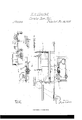
- Figure l is a top view of the mill; Fig. 2 a longitudinal section on the red line A, B; Fig. 3 a transverse section on red line C, D; Fig. l a longitudinal section of inclined plane.
- the object of my improvements is, to produce the set, or movement of the log toward the saw, by ⁇ self-acting apparatus or machinery, so that the mill shall be a selfsetting mill, and the set of the log to any desired thickness be accomplished by mechanical means. This object is accomplished by the means and in the manner following.
- the outer side of the carriage is a shaft or rod running lengthwise of the carriage, having at each end a pinion, which meshes into a rack attached to the block, so
- a lever is connected with it which protrudes horizontally from, and at a right angle with, said rod, which lever by means of a cam or eccentric clutches and acts upon the said rod, so that whenever the said lever is raised upward, it clutches the rod and causes it to ,revolve and thereby accomplishes the set.
- an inclined plane is so placed as that the outer end of said lever shall come in contact with the inclined surface of said plane, and shall travel up said surface (the said plane being stationary,) as the carriage passes one way, while as the carriage passes the other way, the lever, by means of a oint or hinge in its outer end, on striking the ?',plane gives way at once so that it shall produce no movement of the rod, or in any way retard the carriage, and is folded up till it passes the plane, when it is again by means of a spring thrown out at its full length.
- This inclined plane is made with an adjustable surface, whereby the incline can be raised at pleasure, and this surface or incline Vis elevated and-:depressed by a lever; and as the height of this incline regulates the upward movement of the lever acting upon the set-rod, which lever passes, as the carriage moves by the plane, up this incline,-the revolution of the set-rod may be made greater or less by elevating or depressing the incline or surface of the plane.
- This lever acts by means of its cam or eccentric upon the rod only as it is moved upward by the inclined plane, while as soon as said lever has passed up said surface, the said lever falls by its own weight into its former horizontal position,the cam or eccentric at once releasing its hold or clutch upon the rod as the lever falls down into place.
- a wheel with a broad, even surface may be attached to the said rod firmly, and the cam or eccentric made to act upon the surface of the wheel, whereby a broader and less angular surface shall be presented to the cam or eccentric, and the gripping or clutch be greater and more regular.
- This mill is designed to cut by both forward and backward motion, or, if desired, at the forward movement of the carriage only, and then the carriage to gig back for the next cut.
- the machinery producing the set is slightly different from what it is in the other case.
- the mill up one of the planes, while at the same time the log is leaving the saw at the end of one cut and is again approaching it, by the movement of the carriage being reversed, for the next cut.
- the mill is to cut at the forward movement only, but one inclined plane is used, so placed as that the set shall be completed just before the log reaches the saw on the forward movement of the carriage.
- Power is applied to the shaft or arbor which carries the saw; this shaft is connected by a band with another shaft which is connected by beveled gear with a shaft having two loose pinions and a sliding clutch, which last mentioned shaft is placed parallel with the length of the carriage and at a right angle with the carriage shaft, and is connected with said carriage shaft by beveled gear.
- the saw arbor or shaft is made to revolve, thereby setting in motion the second shaft, and also the third shaft having on it the pinions and clutch.
- the clutch As the clutch is affixed to, and revolves with, the shaft, it causes whichever of the two loose pinions it seizes to revolve with the shaft; and as the pinion meshes into the cog wheel upon the carriage shaft, this wheel is at once set in motion by the pinion, and consequently the carriage shaft, to which this wheel is affixed, is made to revolve, thereby turning its pinion which meshes into a rack upon the carriage, and thus setting the carriage in motion.
- the carriage moves along by the saw till the trip or stud upon it strikes a lever attached to the clutch, when at once the clutch is shifted to the other pinion, and the movement of the carriage is reversed; the carriage then moves back by the saw till another trip or stud upon the other end of the carriage strikes the clutch lever, thereby shifting the clutch to the lirst pinion and again reversing the movement of the carriage.
- A is the frame containing the saw arbor shafts and beveled gear
- B the frame of the carriage
- C, C the rails or tracks upon which the carriage wheels move by reason of the rack D, on the bottom of the carriage meshing into the pinion E on the carriage shaft F protruding from the saw frame.
- the saw S is secured upon the shaft G in the usual manner, and is driven by a band passing around the pulley H, and put in motion by any motive power.
- This shaft G gives motion to the shaft I by reason of the band K connecting said shafts Gr and I.
- the shaft I has a cogwheel or pinion which meshes into a cog wheel upon the shaft L which runs at a lis connected by the pinion E as above stated.
- the lever P moves the clutch M whenever either of the trips Q, Q upon the carriage strikes it.
- the set-rod J On the outer side of the carriage is the set-rod J having on its extremities the pinions R, R meshing into the racks S, S attached to the block T.
- a lever U movable around the rod except when the cam (or eccentric) V fixed in the lever next to the set rod clutches the rod as the lever is raised upward.
- This lever U extends horizontally, or nearly so, from the set rod, and is so held that the outer end cannot be depressed, but can be raised.
- the inclined plane W is the plane' with an ad just-able incline, so placed as that the lever U, as the carriage passes the plane, shall come in contact with the plane, and shall pass up the incline as the carriage passes one way, but shall, as' the carriage passes the other way, fold up by means of a hinge in the lever.
- the incline of the plane is raised or depressed by a screw and lever.
Landscapes
- Life Sciences & Earth Sciences (AREA)
- Forests & Forestry (AREA)
- Engineering & Computer Science (AREA)
- Mechanical Engineering (AREA)
- Transmission Devices (AREA)
Description
UNITED STATES PATENT OFFICE.
KINGSLEY R. OLMSTED,
or CHICAGO, ILLINOIS.
LATERAL FEED-MOTION FOR SAWING-MILLS.
Specicaton of Letters Patent No. 18,599, dated November 10, 1857.
To all whom it may concern:
Be it known that I, KINGSLEY R. OLMSTED, of Chicago, in the county of Cook and State of Illinois, have invented new and useful Improvements in Sawing-Machines, which machines are commonly called Sawmills; and Ido declare that the following is a full,
clear, and exact description of the construction and operation of the same, reference being had to the annexed drawings, making a part of this specilication, in which Figure l is a top view of the mill; Fig. 2 a longitudinal section on the red line A, B; Fig. 3 a transverse section on red line C, D; Fig. l a longitudinal section of inclined plane.
, The object of my improvements is, to produce the set, or movement of the log toward the saw, by `self-acting apparatus or machinery, so that the mill shall be a selfsetting mill, and the set of the log to any desired thickness be accomplished by mechanical means. This object is accomplished by the means and in the manner following.
Cn the outer side of the carriage is a shaft or rod running lengthwise of the carriage, having at each end a pinion, which meshes into a rack attached to the block, so
Y that the revolution of the shaft or rod gives motion by means of said pinions and racks to the head and tail blocks, which produces the set of the log; and in order to give the requisite amount of revolution to this rod, a lever is connected with it which protrudes horizontally from, and at a right angle with, said rod, which lever by means of a cam or eccentric clutches and acts upon the said rod, so that whenever the said lever is raised upward, it clutches the rod and causes it to ,revolve and thereby accomplishes the set.
In order to give this upward movement to the lever, an inclined plane is so placed as that the outer end of said lever shall come in contact with the inclined surface of said plane, and shall travel up said surface (the said plane being stationary,) as the carriage passes one way, while as the carriage passes the other way, the lever, by means of a oint or hinge in its outer end, on striking the ?',plane gives way at once so that it shall produce no movement of the rod, or in any way retard the carriage, and is folded up till it passes the plane, when it is again by means of a spring thrown out at its full length. This inclined plane is made with an adjustable surface, whereby the incline can be raised at pleasure, and this surface or incline Vis elevated and-:depressed by a lever; and as the height of this incline regulates the upward movement of the lever acting upon the set-rod, which lever passes, as the carriage moves by the plane, up this incline,-the revolution of the set-rod may be made greater or less by elevating or depressing the incline or surface of the plane. This lever acts by means of its cam or eccentric upon the rod only as it is moved upward by the inclined plane, while as soon as said lever has passed up said surface, the said lever falls by its own weight into its former horizontal position,the cam or eccentric at once releasing its hold or clutch upon the rod as the lever falls down into place. To enable this cam or eccentric to clutch the rod with more closeness, a wheel with a broad, even surface may be attached to the said rod firmly, and the cam or eccentric made to act upon the surface of the wheel, whereby a broader and less angular surface shall be presented to the cam or eccentric, and the gripping or clutch be greater and more regular. i
From the above description of the self` setting apparatus the operation of the same will be easily comprehended. The carriage as it passes along brings the protruding end of the lever in contact with the foot of the inclined plane; the lever having rollers at its end, the end travels up the incline as the carriage moves along and is thereby raised upward; this lever as it is raised presses the cam or eccentric which is affixed in it, upon the surface of the wheel aflixed to the rod or shaft, thereby causing the rod to turn or revolve till the incline is completely passed; the rod, as it turns, turns the pinions, and these pinions move the racks into which they mesh; and these racks Aby this movement push up their blocks, and these blocks, hold ing the log firmly by their dogs, move up the log toward t-he saw, and thus the set for the next cut is completed.
This mill is designed to cut by both forward and backward motion, or, if desired, at the forward movement of the carriage only, and then the carriage to gig back for the next cut. In the one case the machinery producing the set is slightly different from what it is in the other case. When the mill up one of the planes, while at the same time the log is leaving the saw at the end of one cut and is again approaching it, by the movement of the carriage being reversed, for the next cut. When the mill is to cut at the forward movement only, but one inclined plane is used, so placed as that the set shall be completed just before the log reaches the saw on the forward movement of the carriage.
Power is applied to the shaft or arbor which carries the saw; this shaft is connected by a band with another shaft which is connected by beveled gear with a shaft having two loose pinions and a sliding clutch, which last mentioned shaft is placed parallel with the length of the carriage and at a right angle with the carriage shaft, and is connected with said carriage shaft by beveled gear. The saw arbor or shaft is made to revolve, thereby setting in motion the second shaft, and also the third shaft having on it the pinions and clutch. As the clutch is affixed to, and revolves with, the shaft, it causes whichever of the two loose pinions it seizes to revolve with the shaft; and as the pinion meshes into the cog wheel upon the carriage shaft, this wheel is at once set in motion by the pinion, and consequently the carriage shaft, to which this wheel is affixed, is made to revolve, thereby turning its pinion which meshes into a rack upon the carriage, and thus setting the carriage in motion. The carriage moves along by the saw till the trip or stud upon it strikes a lever attached to the clutch, when at once the clutch is shifted to the other pinion, and the movement of the carriage is reversed; the carriage then moves back by the saw till another trip or stud upon the other end of the carriage strikes the clutch lever, thereby shifting the clutch to the lirst pinion and again reversing the movement of the carriage.
In the drawings annexed A is the frame containing the saw arbor shafts and beveled gear; B the frame of the carriage; C, C, the rails or tracks upon which the carriage wheels move by reason of the rack D, on the bottom of the carriage meshing into the pinion E on the carriage shaft F protruding from the saw frame. The saw S is secured upon the shaft G in the usual manner, and is driven by a band passing around the pulley H, and put in motion by any motive power. This shaft G gives motion to the shaft I by reason of the band K connecting said shafts Gr and I. The shaft I has a cogwheel or pinion which meshes into a cog wheel upon the shaft L which runs at a lis connected by the pinion E as above stated.
The lever P moves the clutch M whenever either of the trips Q, Q upon the carriage strikes it.
On the outer side of the carriage is the set-rod J having on its extremities the pinions R, R meshing into the racks S, S attached to the block T. Upon the rod J is a lever U movable around the rod except when the cam (or eccentric) V fixed in the lever next to the set rod clutches the rod as the lever is raised upward. This lever U extends horizontally, or nearly so, from the set rod, and is so held that the outer end cannot be depressed, but can be raised. The inclined plane W is the plane' with an ad just-able incline, so placed as that the lever U, as the carriage passes the plane, shall come in contact with the plane, and shall pass up the incline as the carriage passes one way, but shall, as' the carriage passes the other way, fold up by means of a hinge in the lever. The incline of the plane is raised or depressed by a screw and lever.
Having fully described the construction and operation of my improved saw mill, what I claim therein as new, and desire to secure by Letters Patent, is-
The combination of a lever and cam, or eccentric, with an inclined plane, set-rod, wheels and racks, constructed, arranged and operated, substantially, in the manner and for the purposes herein set forth.
KINGSLEY R. OLMSTEI).
Witnesses:
H. F. VVAITE, J. HABLAN Woon.
Publications (1)
| Publication Number | Publication Date |
|---|---|
| US18599A true US18599A (en) | 1857-11-10 |
Family
ID=2082044
Family Applications (1)
| Application Number | Title | Priority Date | Filing Date |
|---|---|---|---|
| US18599D Expired - Lifetime US18599A (en) | Lateral eeed-motlow for sawiktg-mills |
Country Status (1)
| Country | Link |
|---|---|
| US (1) | US18599A (en) |
Cited By (1)
| Publication number | Priority date | Publication date | Assignee | Title |
|---|---|---|---|---|
| US20050114823A1 (en) * | 2003-11-26 | 2005-05-26 | Bernd Kuchler | Method for improving a simulation model of photolithographic projection |
-
0
- US US18599D patent/US18599A/en not_active Expired - Lifetime
Cited By (1)
| Publication number | Priority date | Publication date | Assignee | Title |
|---|---|---|---|---|
| US20050114823A1 (en) * | 2003-11-26 | 2005-05-26 | Bernd Kuchler | Method for improving a simulation model of photolithographic projection |
Similar Documents
| Publication | Publication Date | Title |
|---|---|---|
| US18599A (en) | Lateral eeed-motlow for sawiktg-mills | |
| US24079A (en) | evarts | |
| US24445A (en) | Shingle-machine | |
| US10778A (en) | Circular sawing machine | |
| US10362A (en) | Steaw-ctttter | |
| US10538A (en) | Method of operating- saws | |
| US28787A (en) | Spoke-machine | |
| US16854A (en) | Pobtable becipbocatlira cibctjxab sawing machine | |
| US22546A (en) | Device for setting laterally circtjlak | |
| US17112A (en) | purmort | |
| US24172A (en) | Saw-filee | |
| US15467A (en) | bailey | |
| US20292A (en) | Improved method of feeding the bolt in lath-machines | |
| US13522A (en) | Dovetailing-machine | |
| US25778A (en) | Locomotive crosscut-sawing | |
| US12337A (en) | Sawing-machine | |
| US19461A (en) | Shoe-peg machine | |
| US20184A (en) | Sawing-machine | |
| US65517A (en) | sweetl-and | |
| US19692A (en) | Machine for sawing staves | |
| US14485A (en) | Improved method of adjusting reciprocating saws | |
| US22058A (en) | Lath-machine | |
| US23887A (en) | Machine for sawing shingles | |
| US21886A (en) | knight and d | |
| US16157A (en) | Method of |