US1859999A - Sound record printing - Google Patents
Sound record printing Download PDFInfo
- Publication number
- US1859999A US1859999A US365870A US36587029A US1859999A US 1859999 A US1859999 A US 1859999A US 365870 A US365870 A US 365870A US 36587029 A US36587029 A US 36587029A US 1859999 A US1859999 A US 1859999A
- Authority
- US
- United States
- Prior art keywords
- film
- printing
- sound
- aperture
- light
- Prior art date
- Legal status (The legal status is an assumption and is not a legal conclusion. Google has not performed a legal analysis and makes no representation as to the accuracy of the status listed.)
- Expired - Lifetime
Links
Images
Classifications
-
- G—PHYSICS
- G03—PHOTOGRAPHY; CINEMATOGRAPHY; ANALOGOUS TECHNIQUES USING WAVES OTHER THAN OPTICAL WAVES; ELECTROGRAPHY; HOLOGRAPHY
- G03B—APPARATUS OR ARRANGEMENTS FOR TAKING PHOTOGRAPHS OR FOR PROJECTING OR VIEWING THEM; APPARATUS OR ARRANGEMENTS EMPLOYING ANALOGOUS TECHNIQUES USING WAVES OTHER THAN OPTICAL WAVES; ACCESSORIES THEREFOR
- G03B27/00—Photographic printing apparatus
- G03B27/02—Exposure apparatus for contact printing
- G03B27/10—Copying apparatus with a relative movement between the original and the light source during exposure
Definitions
- Thisinvention has to do generally with photographic sound records. and more particularly with the extirpation of defects or extraneous effects or characteristics in the sound record track which cause undesirable noises in reproduction, or, in another aspect, with obliterating certain parts of the sound record which are not desired to be iinally re.
- the well known pair of parallel transparent lines which are printed on the positive film 'from a patch in the negative.
- the cause of these lines may be seen by holding a nega.- tive iilm having a usual patch therein up to the light, when a pair of black lines will appear laterally across the film. one at each of the overlapping film ends.
- a positive film printed from a negative having such a patch will then, of course. have a corresponding pair of transparent lines. and if this positive be used in sound reproduction without retouching or blacking out these lines, there will be heard two distinct. sharp noises as the transparent lines pass before the photo-electric cell in the reproducing system.
- the printing machine is provided with means for obliterating such sound producing characteristics by exposing the portions of the positive in which they would otherwise be printed to actinic light rays, this operation being accomplished while the positive is being printed from the patched negative.
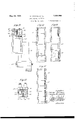
- Fig. 1 is a vertical section of a portion of a. typical printing machine with our invention applied thereto;
- Fig. 2 is a plan view of the device shown in Fig. 1;
- Fig. 3 is a view taken on line 3--3 of Fig. 1, parts being removed;
- Fig. 4 is a vertical section taken on line 4.-4 of Fig. 1;
- Fig. 5 is a side elevation of the masking device for the printing aperture
- Fig. 6 is a vertical section taken on line 6-6 of Fig. 5;
- Fig. 7 is a vertical section taken on line 7 7 of Fig. 5; n
- Figs. 8, 8a, 8b and 8c are front elevations of the masking device, looking in the. direction of arrows 8-8'of Fig. 5, and showing the device in various operative positions;
- Fig. 9 is a. perspective view of a light shield
- Fig. 1() is a. horizontal section taken on line 10-10 0f rig. 5;
- Fig. 11 is afragmentary view showing the swinging' aperture gate and spark plugs mounted thereon;
- FIG. 12 is a section taken on line 12-12 of Fig. 13 shows a negative film having a. splice therein. and showing the sound track and lin notch;
- Fig. 14 is a corresponding positive lm showing the splice image blacked out in the sound track
- Fig. 15 is a perspective view of the circuit maker
- Fig. 16 is a detail showing a lm spool used in association with the circuit maker
- Fig. 17 is a diagram of an electrical circuit embodying our invention.
- Fig. 18 shows a film illustrating a use of our invention.
- the numeral 10 indicates a frame casting of a typical printer to which the present invention has been applied.
- This casting is provided with a connecting portion 11 adapted to be secured to the lamp house, not shown, of the printer.
- Connecting portion 11 comprises upper and lower walls l2 and 13, respectively, and side walls 14 and 15, respectively, the opening between these walls being 1ncommunication with the lamp chamber of the lamp houseL and forming a light conduit 17 to the printing aperture, hereinafter described.
- These walls 12 to 15 are formed integral with a vertically extending extension frame 18, and merge into av hollow cylindric casing portion 19 extending outwardly therefrom.
- Casing 19 has a horizontal bore 20.
- a bush 22 is secured in the portion of bore 20 lying to the rear of conduit 17, and a, sprocket shaft 23 is supported for rotation in a concentric bore of-this bush.
- a pair of spaced sprocket wheels 25 and 26 mounteded on sprocket shaft 23 and disposed in line with light conduit 17 is a pair of spaced sprocket wheels 25 and 26. respectively.
- Sprocket wheel 26 is formed integral with shaft 23 and is located adjacent the hub of bush 22. and sprocket wheel 25 is screwed to a ange 28 provided on the end of sprocket shaft 23.
- the rim portions 29 of the two sprocket wheels are spaced by the distance between the rows of perforations on a film, and are provided with teeth adapted to drivingly engage such perforations.
- a curved plate 31 is secured in the bore 20 of casing 19 just below said rectangular cut 30, and extends upwardly beyond the lower edge thereof to define the lower edge of a printing aperture 32.
- the upper end of plate 30 is shaped outwardly to form a face 33 lying closely adjacent the film as it passes thereover.
- Another curved plate 34 is mounted within the bore of casing l9 above the rectangular cut 30 therein, the lower end of the plate extending downwardly beyond the upper edge of the cut to define the upper edge of printing aperture 32.
- the lower end of this plate is shaped outwardly to form a face 35 lying closely adjacent the lm as it passes thereover.
- the rim portions 29 of the sprocket wheels 25 and 26 overhang inwardly toward each other so as to overhang the edges of plate 34 (see Figure 4), and thus form light tight joints.
- the upper end of plate 34 is secured to the underside of a curved bracket 38 extending rearwardly over sprocket wheel 25 and formed on the outer end of an arm 39, which arm extends radially from the inner'end of a shaft 40 in axial alinement with sprocket shaft 23.
- bracket 38 underside of bracket 38 is provided with an arcal groove 41 concentric with sprocket wheel 25 through which the rim portion and sprocket teeth of this wheel pass.
- Shaft 40 runs through a hollow shaft 42. which. in turn, is journaled in a bearing 43 formed concentrically in a cap 44 secured over the outer end of casing 19. Shaft 40 extends out through cap 44 and is secured against rotation at its outer end in the usual manner. indicated in Figure 3.
- the means of securing shaft 40 against rotation, andthe other adjuncts seen on the outer surface of cap 44 in Figure 3, are usual and well known. and need not here be further described.
- Fitted in bore 20 and facing light conduit 17 is a light shield 46, having a light opening 47 through which light may pass to reach the printing aperture 32.
- Openingr 47 is varyingly closed to vary the intensity of the printing light by means of a light changing shutter 48, which is carried on the4 outer end of au arm. not shown. fastened on the inner end of hollow shaft 42. shaft 42 being rotated in the usual manner to control the intensity of the printing light.
- a light changing shutter 48 which is carried on the4 outer end of au arm. not shown. fastened on the inner end of hollow shaft 42. shaft 42 being rotated in the usual manner to control the intensity of the printing light.
- the cut 30 in casing 19 is made in a direction substantially tangential to the axis of bore 20. and secured on the tangential surfaces so formed are upper and lower stripper plates 50 and 51, respectively7 (see Figures 1 and 3). which extend toward each other and terminate just short of the printing aperture.
- the usual film gate is shown at 52 mounted upon the upper end of an arm 53 pivotally mounted upon a stud 54 extending from frame 18.
- the gate 52 is arranged to swing from its inoperative position, indicated in the dotted lines of the figure, to its operative position within the opening 30 of casing 19 and closely adjacent sprocket wheels 25 and 26.
- the gate thus backs upv the superposed negative and positive films N and P as they pass from the upper stripper plate 50 onto sprocket wheels 25 and 26 to be carried over the printing aperture 32, and are then picked up by the lower stripper plate 51.
- the negative film is threaded from the usual supply spool, not shown, over a sprocket 55 rotatably mounted on the upper end of frame 18. then behind gate 52 and over sprocket 25, 26, then over a sprocket 56 rotatably mounted on the lower end of frame 18, and finally down to wind upon a film receiving spool, not shown.
- Apositive film P is threaded from a film supply spool, not shown, over sprocket 55 in superposed position with the negative film, then behind gate 52 over sprocket 25, 26 in superposed printing relation with the negative film, then over sprocket 56, and finally down to be wound upon a film receiving spool, not shown.
- Sprockets 55 is threaded from the usual supply spool, not shown, over a sprocket 55 rotatably mounted on the upper end of frame 18. then behind gate 52 and over sprocket 25, 26, then over a sprocket 56 rotatably mounted on the lower end
- the illustrative printing machine herein described is preferably provided in connection with its printing aperture with a masking device, completely described in an application having Ser. No. 364,514, filed May 20,
- the masking device above referred to includes a plate 65 which is curved to conform to the undersideof plate 34, and is secured thereto, as shown best in Figures l and 4 see also Figures 5 to 10, inclusive). 'llhe forward end of plate 65 terminates somewhat above the lower edge of plat-e 34 and is provided with three slots, 66, 67 and 68, in which are pivotally mounted masking-wings 69. 7() and 71, respectively, each adapted individually to close a selected area of the printing aperture 32, as hereinafter explained.
- the two outside masking wings 69 and 71 include lugs 72 which are taken within slots 66 and 68 pivoted therein on a pivot pin 73 carried on pin 73.
- Lug 76 extends downwardly below the lower end of plate 65 at the width of slot 67, as shown in Figure 8.
- Wings 69 and 71 have portions 77 of increased width joining lugs 7 2 below plate 90, the inner edges thereof just contacting with the edges of lugs 76 of the middle wing 70, and the outer edges thereof lying in the extended lines of the edges of plate 65. ⁇
- Middle wing lug 7 6 and outside-wing portion 77 extend downwardly to the lower edge 34a of plate 34 (see Figure l0.
- the outside wings are undercut from their inner edges to form reduced mask portions 78 and 79, respectively, of widths just greater than the width of a sound record track, as hereinafter explained, while the middle wing is correspondingly increased in width and forms a mask portion 480, the outside edges of which lie in contact with the inside edges of mask portions 78 and 79 of the outside wings.
- Fitted on the outer surfaces of mask portions 78 and 79 of the two out-side wings and 80 of the middle wing, are aperture-closing rask elements 81, 82 and 83.
- Plate 65 is made of the same width as plate 34, and is thus slightly greater in width than thc spacing between the rim portions 29 of the two sprocket wheels, which overhang its two edges as shown in Figure 4.
- the three elements 81, 82 and 83 are together just equal to the width between the rows of perforations on the hlm, and therefore fit nicely between the rim portions of the two sprocket wheels, as shown in Figure 3.
- rlhe widths of elements 81 and 82 of the outside masks are each equal to the width of a sound l ⁇ record track: and the device is so proporthe three elements 81, 82 and 83 is equal to the width between the sprocket wheels, or in other words. to the hlm width between perforations-the other of the outside elements 81 and 82, taken with the middle element 83,
- Each of the wings 69, 7 0 and 71 may be swung to an inoperative position, as is wing 71 in Figure 1, thus allowing printing to be done in the corresponding area of aperture 32.
- the means of shifting the wings betveen operative and inoperative positions will now be described.
- lVings 69, 70 and 71 are provided just below their pivotal connections with the forward end of plate with slots 86, within which the formed ends of links 87 are pivotally connected to the wings.
- the rear ends of links 87 are pivotally connected within slots 88 to the lower ends of swinging arms 89, arms 89 being in turn pivotally connected within slots 90 to the lower edge of a plate 91 secured at its upper edge to plate 65.
- Also pivotally connected within slots 88 to the lower ends of arms 89 are links 92, which extend rearwardly to connect with the lower ends of wings-actuating levers 93, 94 and 95, which correspond respectively to masking-wings 69, and 71.
- Levers 93, 94and 95 extend upwardly and outside of casing 19 through an aperture 96 provided in the upper wall 12 of light conduit 17.
- the levers also extend through openings 97 of a plate 98 secured to the upper surface of wall 12, and are pivotally supported therein by means of a pivot pin 99 which passes horizontally through the plate in the line of openings 97.
- the upper ends of levers 93, 94 and 95 are provided with handles 93a, 94a, and 95a, respectively, by means of which the levers are shifted to operate the maskingwings.
- levers are all shown in position to hold the masking-wings forward or in masking position.
- the front lever is shown shifted forward, which, through the medium of links 92 and 87, has swung masking-wings 7l back to an inoperative position out of the line of the light rays passingfrom light opening 47 to the printing aperture.
- Light shields 100 are provided to the rear of the masking-wings, and adapted to overlap their meeting edges at the printing aperture.
- Each light shield is provided at its upper end with a lug 101 which is taken Within a slot 102 provided in the upper end of middle wing 76, and is pivotally connected therein by means of a pivot pin 7 3.
- the maskingwings are forward, as in Figures 5 and 6, the light shields lie flat against their inner surfaces, and are curved to conform thereto, as shown. When one of the wings is moved back, however, it carries with it the corresponding light shield, as shown in Figure 1.
- the method of operating the masks during a typical printing operation is as follows: It will be assumed, for example, that the sound record is to be printed on the positive first, and the action last, and that the sound negative film is arranged in the machine with its sound track located at its left hand edge. Then to print this sound track upon the positive while masking the picture area thereof, the masking-wings are actuated by means of levers 93, 94 and 95 to take the positions of Figure 8. Wing 69 is then back, allowing the sound record to be printed through the aperture area thereby opened, while wings 70 and 71 are forward and together mask the picture area of the film. When the films have been run through the machine in this manner, the positive roll is removed from its receiving spool, turned over, and replaced on the supply spool.
- This operation causes the positive film to be reversed from right to left with respect to the printing aperture, and its sound track to be at the opposite side edge of the printing aperture from that at which it was originally printed.
- the action negative is then arranged in the machine with its picture area at the left hand edge of the sound track in correspondence with the action area of the positive; and the masks are then arranged to print the action by merely shifting the middle wing back to its inoperative position along side of wing 69, as shown in Figure 8a. Wings 69 and 70 are then back, allowing the action to be printed through the aperture area thereby left open, while wing 71 remains forward to mask the previously printed sound record.
- the mask will first be arranged as in Figure 8b to print the sound track and to mask the action area, and then split and arranged as in Figure to print the action and mask the previously printed sound track, as will be understood Without further explanation.
- the mechanism for controlling the above mentioned light changing shutter i8 is then .actuated by means of an electrical circuit-maker provided with a pair of electrical contacts which derive their movement from a roller riding in Contact with this notched edge of the film.
- an electrical circuit-maker provided with a pair of electrical contacts which derive their movement from a roller riding in Contact with this notched edge of the film.
- the roller follows the indentation thereof and closes the circuit for operating the light changing mechanism.
- This roller is mounted on the printer in. such relation to the printing aperture that the light change is edected just as the splice reaches the aperture.
- the printing light is changed at each splice, or as each successive scene reaches the printing aperture.
- roller 61 shown best in the detail of Fig. 16, is provided at its forward end with the usual flange 63, but terminates short of the rear edge of the iilm, as shown, there being no flange provided at its rear end.
- Circuit-maker 115 which may be similar to another circuit-maker hereinafter mentioned and illustrated in Figure 15, is provided with a movable roller 116 whichrides in contact with the notched edge of the negative film as it passes over roller 61, and is spring-pressed there-against to follow the indentations of the notches (see Figures 1 and 2) This described movement of roller 116 acts to close a pair of electrical contacts in circuit-maker 115, whereby the light changing mechanism is actuated, as hereinabove referred to.
- the overlapping ends 110 and 111 of the spliced' negative shown in ' Figure 13 appear as a pair of black lines; and in the positive hlm printed from this negative (see Figure 14) the splice image appears as a corresponding pair of transparent lines 110 and 111', as hereinabove explained.
- the numeral 120 indicates the sound track, here shown as having no sound record at the loca-tion of the splice, and it will be seen that the transparent lines run directly across the sound track, the eidect of these lines, as previously explained, being to produce la loud and objectionable noise as they pass the photo-electric cell in reproduction.
- this edect is obviated by exposing the sound track of the positive to actinic light rays at the location of everyr splice so that the described pair of transparent lines will be darkened or blacked out, all sound reproducing characteristics of the light-adected area being obliterated.
- the operation is carried out simultaneously with the printing of the positive, and by utilizing the previously described film notch which has been cut adjacent each lilm splice for the purpose of actuating the light-changing circuit-maker, to actuate similarly a second circuit-maker which is adapted to close a circuit to an illuminant located opposite the sound track, all being arranged in such manner that the circuit-maker is actuated to light up the illuminant just as the splice passes thereby, thus causing a sound track area of the positive including the splice image to be obliterated of all sound reproducing characteristics.
- this circuit-maker includes an enclosing frame 126, a cross-piece 127 of insulating material pivotally mounted in the enclosing frame, a swinging arm 128 extending radially from the cross-piece through a slot provided in the end of the frame, a pair of contact arms 129 of conductive material mounted on the cross-piece, a second pair of contact arms 130 mounted on the frame and adapted to be contacted with respective contact arms 129 when the lever arm is in one position of its movement, and a spring 131 normally tending to move the swinging arm to cause contact of arms 129 and 130.
- the circuit-maker is mounted with arm 128 extending downwardly, and the lower end of this arm is provided with a roller 132 which rides on the notched edge of the film as it passes over roller 61.
- the device is so arranged that spring 131 urges the roller 132 into contact with the edge of the film as it passes over roller 61, but the film edge is so located with respect to the roller that arm 128 is normally held thereby back against spring 131 to maintain contacts 129 and 13() open. But when a film notch 112 reaches the roller, the roller follows the indentation thereof under the action of spring 132, and the resulting movement of the device is sufficient to close contacts 129 and 130. These contacts close an electrical circuit, hereinafter described, to an illuminant located over the sound track of the film.
- illuminants Two of these illuminants are provided, one at each edge of the film, so that operation may be carried on with the sound track located at either of said edges.
- These illuminants take the form of a pair of spark plugs 140 and 141, respectively, mounted on the upper end of gate 52 (see Figs. 1, 11 and 1,2), with their axes substantially perpendicularmwhen the gate is in its operative position, shown in the full lines of Figure l-to the superposed positive and negative films passing over the upper stripper plate 50.
- the inner ends 142 of the spark plugs are secured within metallic blocks 143 bracketed upon the upper end of the swinging gate-arm 53. Blocks 143 are hollow in front of the plugs and present open ends toward the film.
- cover-plates 145 each of which has a slot or light-aperture 146.
- One of these slots covers the sound track area of a film passing thereunder when the sound track is located at one edge of the lm, and the other of the slots covers the sound track area of the l ilm'when the sound track is located at the ranged that cover-plates 145 lie closely adjacent the positive film passing thereunder when the gate is swung to its operative position, as indicated in the full lines of Figure 1.
- the distance between the roller of circuit-maker 125 and the slots 146 before spark plugs 140 and 141 is made equal to the distance on the negative film between the film splice and its notch 112, so that the plug which is over the sound track is sparked as the splice passes under its slot.
- the result is that the sound track is light-affected at the location of the splice, and upon development of the positive, a darkened-area 148 (see Figure 14) appears in the sound track and obliterates any sound reproducing characteristics therein.
- the plug of course, remains sparking during the time that roller 142 is within notch 112, and the result of this is that the darkened area 148 is of substantially the length of the film notch rather than of the slot 146.
- Slots 146 are provided with slanting upper and lower edges 162 and 163, respectively, as shown best in Figure 11, so that the darkened sound track area 148 (see Figure 14) will have corresponding slanting edges 162 and 163', respectively. The slant of these edges is made so gradual that the light change caused thereby is not of a frequency which will cause any sound to be heard as they pass thephoto-electric cell in reproduction.
- spark plug flash Any other source of illumination other than a spark plug, s uch as a small incandescent bulb, or non-filament glow tube, can be utilized if desired.
- a spark plug flash has high actinic value, and has been found convenient and satisfactory. Or there can be utilized a constantly illuminated illulninant and a controlled mechanical shutter.
- the electrical circuit which connects circuit-maker with the two spark plugs includes a switching arrangement which automatically selects the proper spark plug in accordance with whichever side of the film the 110 sound track may be located at in any given instance.
- This switching arrangement may -be embodied as follows:
- switch blades 150, 151 and 152 Secured to levers 93, 94 and 95 at points above their pivotal lnountings in plate 98 115 are switch blades 150, 151 and 152, respectivef ly (see Figures 1 and 2). Blades 150 and 152 of the outside levers extend forwardly therefrom, and are adapted to contact spring contacts 153 and 154, respectively, when the 120 levers are shifted forwardly, as in lever 95 in Figures 1 and 2.
- Switchblade 151 extends rearwardly from lever 94, and is adapted to contact a pair of spring contacts 155 mounted on plate 98', when lever 94 is shifted to its 125 rearward position, as in Figures 1 and 2.
- levers 93, 94 and 95 in addition to actuating masking-wings 69, 70 and 71, also actuate switches -153, 151-155, and 152- 154.
- switches 98 or 95 are shifted for- 130 ward to swing their respective maskingwings out of the printing aperture, their respective switches are closed, and when the same levers are shifted rearward to move their masks into the printing aperture, their switches are opened.
- the middle lever 94 is shifted forward to move its mask out of the printing aperture, its switch is opened, and when the lever is shifted rearward to move its mask into the printing aperture, its switch is closed.
- switch blades 150, 151 and 152 are all connected together by a wire loop 160.
- wire 161 that goes to one pair of contacts of circuit-maker 125, the other contacts of which are connected by means of wire 162 with a battery B.
- lVire 162 is grounded to the printer.
- wire 163 that branches to go to one of the pair of low tension terminals of each of two spark coils 164 and 165.
- lever 93 When it is desired to print a sound record from a negative which has its sound track located at the left hand edge, as viewed in Figure 13, lever 93 will be shifted forward to swing wing 69 back from the printing aperture; while levers 94 and 95 willbe swung back, with their wings 70 and 71 in masking position over the aperture, all as shown in Figure 8. It will then be noted that switches 150, 153 and 151, 155 are closed, while switch 152 is open.
- the spark plug which energizes plug 141 will then be seen to be in circuit with battery B, circuit-maker 125, and switches 151, 155 and 150, 153; and when a film notch 112 causes the closing of the contacts of circuit-maker 125, plug 141, which is situated over the left hand sound-track area, will be sparked. But since lever 95 is in its rearward position to place wing 71 in maskingposition, switch 152, 154 is open and plug 140 is not sparked. Then, when it is desired to print the action on the positive, lever 94 is shifted to uncover the picture area of the aperture (see Figure 8a), which action opens switch 151, 155 and makes it impossible to spark either plug.
- lever 95 is shifted forward and levers 93 and 94 rearward, which cause the wings to take the positions of Figure 8b, switches 152,
- the electrical circuit may be modified by omitting one of the outside switches, 150, 153, or 152, 154,
- this notch will be made of any length necessary to provide for taking out the required length of the record.
- Figure 18 is shown a positive ilm having a sound record 166, a portion 167 of which has been obliterated in this manner.
- a motion picture machine having a printing aperture, means for moving a defveloped and a fresh actinic film longitudinally past said printing aperture, and a pair of removable masks adapted to extend longitudinally over said aperture, said masks including a sound track mask and an action area mask, the combination of an illuminant adapted to cast actinic light rays over av limited longitudina'l extent of the sound track area of the fresh actinic film, an electric circuit including a source of current connected to said illuminant, means actuated by a notch in the developed film for closing said electrical circuit, and a switch in said electrical circuit automatically opened by virtue of removing [Said action area. mask from said" aperture,
- a motion picture machine having a printing aperture, means for moving a developed and a fresh actinic film longitudinally past said printing aperture, means to mask the sound track area of the film at the printing aperture, and means to mask the action area of the film at the printing aperture, the combination of an illuminant adaptcd to cast actinic light rays over a limited longitudinal extent of' the sound track area of thc fresh actinic film, a normally open electrical circuit including a source of current connected to said illuminant, a switch in said electrical circuit automatically closed when the action area of the film is masked, and opened when the action area of the film is unmasked, and means actuated by a notch in said developed film for closing said electrical circuit.
- a motion picture printing mach-ine having a printing aperture of the width of the printing area on the film, means for moving the film longitudinally past the printing aperture, means for masking a sound track area at either side edge of said aperture, and for masking an action area of the aperture including either of said yside edge areas, the combination of a pair of illuminants adapted to cast light rays over limited longitudinal extents of the sound track areas at opposite edges of the fresh actinic film, a normally open electrical circuit including a source of current connected to said illuminants, a master switch in said electrical circuit automatically closed by Virtue of masking the action area of the said automatically opened by virtue of unmasking said action area, switches controlling the illumination of said illuminants, each of said switches being automatically closed by virtue of unmasking the corresponding sound track area of the printing aperture and automatically opened by Virtue of masking the same sound track area, and, means actuated by a notch in the developed film for closing said electrical. circuit.
Landscapes
- Physics & Mathematics (AREA)
- General Physics & Mathematics (AREA)
- Projection-Type Copiers In General (AREA)
Description
May 24, 1932- s. TWlNiNG E11-AL 1,859,999
SOUND RECORD PRINTING Filed May 25, 1929 5 Sheets-Sheet l:
FMH Fos/TWA- F/@a/z/ MEGA r/ms` :apar span/ sukP/.r :PML
Sidney Training.' Thnx/zas 771. [rig/rma,
May 24., `1932- I s. TwnNnNG ET Aa. 1,859,999
' SOUND RECORD PRINTING Filed May 25, 1929 5 Sheets-Sheet 2 Inl/en ions* a'dlzeg Tmizzizzg.
Iza/724577Z. [22g/22412.
May 24, 1932- s. TWINING ET AL 1,859,999
SOUND RECORD PRINTING Filed May 25, 1929 5 Sheets-Sheet 5 May 24, 1932- s. TWlNsNG ET AL 1,859,999
SOUND RECORD PRINTING tormey.
S. TWINBNG ET AL SOUND RECORD PRINTING May 24, 1932.
Filed May 25 1929 5 Sheets-Sheet 5 DDD-QUEDE Patented May 24, 1932" UNITED STATES PATENT OFFICE SIDNEY TWINING AND THOMAS M. IN GMAN OF LOS ANGELES, CALIFORNIA, ASSIGNORS TO PARAMOUNT PUBLIX CORPORATION, OF LOS ANGELES, CALIFORNIA, A CORPO- RATION 0F NEW YORK SOUND RECORD PRINTING Application filed May 25, 1923. Serial No. 365,870.
Thisinvention has to do generally with photographic sound records. and more particularly with the extirpation of defects or extraneous effects or characteristics in the sound record track which cause undesirable noises in reproduction, or, in another aspect, with obliterating certain parts of the sound record which are not desired to be iinally re.
produced. Although the invention is hereinafter explained from the standpoint. of sound record obliteration. it will be apparent that the invention is equally applicable to any kind of photographic record, whether visual or auditory. The obviation of the results of defects in sound records, however, is the problem of greatest present importance, and the invention will therefore be explained chieiy in this aspect, but without necessary limitation thereto.
As a typical example of such defects or noise producing characteristics, and one which has heretofore caused particular trouble and inconvenience in the obviation of its effect in final reproduction, may be mentioned the well known pair of parallel transparent lines which are printed on the positive film 'from a patch in the negative. The cause of these lines may be seen by holding a nega.- tive iilm having a usual patch therein up to the light, when a pair of black lines will appear laterally across the film. one at each of the overlapping film ends. A positive film printed from a negative having such a patch will then, of course. have a corresponding pair of transparent lines. and if this positive be used in sound reproduction without retouching or blacking out these lines, there will be heard two distinct. sharp noises as the transparent lines pass before the photo-electric cell in the reproducing system. i
To do away with this effect, it has heretofore been necessaryr to go over the entire positive lilm b v hand and blot or paint out each of these patch images. This procedure` however. entails a considerable amount of hand work. and is highly inefficient and undesirable at best.
According to the present invention, the printing machine is provided with means for obliterating such sound producing characteristics by exposing the portions of the positive in which they would otherwise be printed to actinic light rays, this operation being accomplished while the positive is being printed from the patched negative.
The manner of accomplishing this result, as well as the various objects and applications of the invention, will best be left to begathered from the following detailed description of a present preferred embodiment thereof as applied to a typical and well known printing machine, reference forvthis purpose being had to the accompanying drawings, in which:
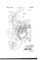
Fig. 1 is a vertical section of a portion of a. typical printing machine with our invention applied thereto;
Fig. 2 is a plan view of the device shown in Fig. 1;
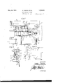
Fig. 3 is a view taken on line 3--3 of Fig. 1, parts being removed;
Fig. 4 is a vertical section taken on line 4.-4 of Fig. 1;
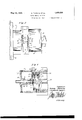
Fig. 5 is a side elevation of the masking device for the printing aperture;
Fig. 6 is a vertical section taken on line 6-6 of Fig. 5; Fig. 7 is a vertical section taken on line 7 7 of Fig. 5; n
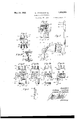
Figs. 8, 8a, 8b and 8c are front elevations of the masking device, looking in the. direction of arrows 8-8'of Fig. 5, and showing the device in various operative positions;
Fig. 9 is a. perspective view of a light shield;
Fig. 1() is a. horizontal section taken on line 10-10 0f rig. 5;
Fig. 11 is afragmentary view showing the swinging' aperture gate and spark plugs mounted thereon;
F Fig. 12 is a section taken on line 12-12 of Fig. 13 shows a negative film having a. splice therein. and showing the sound track and lin notch;
Fig. 14 is a corresponding positive lm showing the splice image blacked out in the sound track;
Fig. 15 is a perspective view of the circuit maker;
Fig. 16 is a detail showing a lm spool used in association with the circuit maker;
Fig. 17 is a diagram of an electrical circuit embodying our invention; and
Fig. 18 shows a film illustrating a use of our invention.
At the outset it is to be explained that although the invention is hereinafter particularly described in connection with the elimination of sound track defects due to film patches, that, broadly considered, the invention is equally applicable to the removal or obliteration of any part of a sound record which is not desired to be heard in reproduction, or of any part of any photographic record whatever.
As the present invention is combined and interconnected, in some of its specific aspects, with certain'operative parts of a printing machine, it will be necessary first to set up in some detail certain of the printerY structure and operation thereof that is pertinent to the present invention before-proceeding to a discussion of the present invention itself.
Referring now to the drawings,.and particularly to Figures 1 and 2, the numeral 10 indicates a frame casting of a typical printer to which the present invention has been applied. This casting is provided with a connecting portion 11 adapted to be secured to the lamp house, not shown, of the printer. Connecting portion 11 comprises upper and lower walls l2 and 13, respectively, and side walls 14 and 15, respectively, the opening between these walls being 1ncommunication with the lamp chamber of the lamp houseL and forming a light conduit 17 to the printing aperture, hereinafter described. These walls 12 to 15 are formed integral with a vertically extending extension frame 18, and merge into av hollow cylindric casing portion 19 extending outwardly therefrom. Casing 19 has a horizontal bore 20. which is in the plane of light conduit 17 and opens thereinto (see Figure 4). A bush 22 is secured in the portion of bore 20 lying to the rear of conduit 17, and a, sprocket shaft 23 is supported for rotation in a concentric bore of-this bush. Mounted on sprocket shaft 23 and disposed in line with light conduit 17 is a pair of spaced sprocket wheels 25 and 26. respectively. Sprocket wheel 26 is formed integral with shaft 23 and is located adjacent the hub of bush 22. and sprocket wheel 25 is screwed to a ange 28 provided on the end of sprocket shaft 23. The rim portions 29 of the two sprocket wheels are spaced by the distance between the rows of perforations on a film, and are provided with teeth adapted to drivingly engage such perforations. On the opposite side of sprockets 25. 26 from light conduit 17 there is provided in cylindric case 1'9 a rectangular opening or cut 30 through.
which the sprocket extends to engage the film.
A curved plate 31 is secured in the bore 20 of casing 19 just below said rectangular cut 30, and extends upwardly beyond the lower edge thereof to define the lower edge of a printing aperture 32. The upper end of plate 30 is shaped outwardly to form a face 33 lying closely adjacent the film as it passes thereover. Another curved plate 34 is mounted within the bore of casing l9 above the rectangular cut 30 therein, the lower end of the plate extending downwardly beyond the upper edge of the cut to define the upper edge of printing aperture 32. The lower end of this plate is shaped outwardly to form a face 35 lying closely adjacent the lm as it passes thereover. The rim portions 29 of the sprocket wheels 25 and 26 overhang inwardly toward each other so as to overhang the edges of plate 34 (see Figure 4), and thus form light tight joints. As shown most clearly in Figures 1 and 4,'the upper end of plate 34 is secured to the underside of a curved bracket 38 extending rearwardly over sprocket wheel 25 and formed on the outer end of an arm 39, which arm extends radially from the inner'end of a shaft 40 in axial alinement with sprocket shaft 23. The
underside of bracket 38 is provided with an arcal groove 41 concentric with sprocket wheel 25 through which the rim portion and sprocket teeth of this wheel pass. Shaft 40 runs through a hollow shaft 42. which. in turn, is journaled in a bearing 43 formed concentrically in a cap 44 secured over the outer end of casing 19. Shaft 40 extends out through cap 44 and is secured against rotation at its outer end in the usual manner. indicated in Figure 3. The means of securing shaft 40 against rotation, andthe other adjuncts seen on the outer surface of cap 44 in Figure 3, are usual and well known. and need not here be further described. Fitted in bore 20 and facing light conduit 17 is a light shield 46, having a light opening 47 through which light may pass to reach the printing aperture 32. Openingr 47 is varyingly closed to vary the intensity of the printing light by means of a light changing shutter 48, which is carried on the4 outer end of au arm. not shown. fastened on the inner end of hollow shaft 42. shaft 42 being rotated in the usual manner to control the intensity of the printing light. The above described parts are usual and well known, and since they form no part of the present invention need not here be further elaborated.
The cut 30 in casing 19 is made in a direction substantially tangential to the axis of bore 20. and secured on the tangential surfaces so formed are upper and lower stripper plates 50 and 51, respectively7 (see Figures 1 and 3). which extend toward each other and terminate just short of the printing aperture.
The usual film gate is shown at 52 mounted upon the upper end of an arm 53 pivotally mounted upon a stud 54 extending from frame 18.. The gate 52 is arranged to swing from its inoperative position, indicated in the dotted lines of the figure, to its operative position within the opening 30 of casing 19 and closely adjacent sprocket wheels 25 and 26. The gate thus backs upv the superposed negative and positive films N and P as they pass from the upper stripper plate 50 onto sprocket wheels 25 and 26 to be carried over the printing aperture 32, and are then picked up by the lower stripper plate 51.
The negative film is threaded from the usual supply spool, not shown, over a sprocket 55 rotatably mounted on the upper end of frame 18. then behind gate 52 and over sprocket 25, 26, then over a sprocket 56 rotatably mounted on the lower end of frame 18, and finally down to wind upon a film receiving spool, not shown. Apositive film P is threaded from a film supply spool, not shown, over sprocket 55 in superposed position with the negative film, then behind gate 52 over sprocket 25, 26 in superposed printing relation with the negative film, then over sprocket 56, and finally down to be wound upon a film receiving spool, not shown. Sprockets 55. 56 and 25, 26 are driven together by a usual train of gears, not shown` mounted in gear case 57 (see Figure 2), and are all driven at 30 the same peripheral speed. Between sprocket 55 and sprocket 25, 26, the positive and negative film pass under movable, weighted, tensioning-rollers 58 and 59, and then over stationary idler rollers 60 and 61, respectively.
The illustrative printing machine herein described is preferably provided in connection with its printing aperture with a masking device, completely described in an application having Ser. No. 364,514, filed May 20,
A.4,0 1929, by Frank E. Garbutt and Thomas iti.
Ingman, entitled Sound picture printer. This device. which greatly facilitates the operation of sound picture print-ing, provides for Athe printing of the sound record at either edge of the film, and the herein specifically described embodiment of lthe present invention is particularly adapted to this arrangement. This specific embodiment of the present invention, however, is fu'llyillustrative of the case in whichthesound record can only be printed at one edge of the film, as will become apparent later.
The masking device above referred to includes a plate 65 which is curved to conform to the undersideof plate 34, and is secured thereto, as shown best in Figures l and 4 see also Figures 5 to 10, inclusive). 'llhe forward end of plate 65 terminates somewhat above the lower edge of plat-e 34 and is provided with three slots, 66, 67 and 68, in which are pivotally mounted masking-wings 69. 7() and 71, respectively, each adapted individually to close a selected area of the printing aperture 32, as hereinafter explained. The two outside masking wings 69 and 71 include lugs 72 which are taken within slots 66 and 68 pivoted therein on a pivot pin 73 carried on pin 73. Lug 76 extends downwardly below the lower end of plate 65 at the width of slot 67, as shown in Figure 8. Wings 69 and 71 have portions 77 of increased width joining lugs 7 2 below plate 90, the inner edges thereof just contacting with the edges of lugs 76 of the middle wing 70, and the outer edges thereof lying in the extended lines of the edges of plate 65.` Middle wing lug 7 6 and outside-wing portion 77 extend downwardly to the lower edge 34a of plate 34 (see Figure l0. At this point vthe outside wings are undercut from their inner edges to form reduced mask portions 78 and 79, respectively, of widths just greater than the width of a sound record track, as hereinafter explained, while the middle wing is correspondingly increased in width and forms a mask portion 480, the outside edges of which lie in contact with the inside edges of mask portions 78 and 79 of the outside wings. Fitted on the outer surfaces of mask portions 78 and 79 of the two out-side wings and 80 of the middle wing, are aperture- closing rask elements 81, 82 and 83. These elements' are congurediat their upper and lower edges 84 and 85, respectively, to Ht snugly-when in forward or masking position-between the upper and lower plate edges 34a; and 30a which define the upper and lower edges of the printing aperture 32 (see Figure 2). 'ihe 'masking elements thus completely fill the aperture, when in masking position` and their outer surfaces are closely adjacent the inner film so that the masking takes place directly at the film surface. Plate 65 is made of the same width as plate 34, and is thus slightly greater in width than thc spacing between the rim portions 29 of the two sprocket wheels, which overhang its two edges as shown in Figure 4. The three elements 81, 82 and 83, however, are together just equal to the width between the rows of perforations on the hlm, and therefore fit nicely between the rim portions of the two sprocket wheels, as shown in Figure 3. rlhe widths of elements 81 and 82 of the outside masks are each equal to the width of a sound l `record track: and the device is so proporthe three elements 81, 82 and 83 is equal to the width between the sprocket wheels, or in other words. to the hlm width between perforations-the other of the outside elements 81 and 82, taken with the middle element 83,
are together equal in width to the film Width between perforations, less the width of a sound track-or in other words, to the width of the picture area of the film. Thus either `outside element forms a sound track mask,
while either outside element together with the middle element form a picture area mask. And no mattervwhether the sound track is set at one edge or the other of the printing area in any given case, one of the outside elements will register with the sound track and form a mask therefor while the other outside element, taken with the middle element togetherl register with the picture area, and thus together comprise a single mask for that area of the film.
Each of the wings 69, 7 0 and 71 may be swung to an inoperative position, as is wing 71 in Figure 1, thus allowing printing to be done in the corresponding area of aperture 32. The means of shifting the wings betveen operative and inoperative positions will now be described. Y
In Figure 5 the levers are all shown in position to hold the masking-wings forward or in masking position. In Figure 1 the front lever is shown shifted forward, which, through the medium of links 92 and 87, has swung masking-wings 7l back to an inoperative position out of the line of the light rays passingfrom light opening 47 to the printing aperture.
Light shields 100 are provided to the rear of the masking-wings, and adapted to overlap their meeting edges at the printing aperture. Each light shield is provided at its upper end with a lug 101 which is taken Within a slot 102 provided in the upper end of middle wing 76, and is pivotally connected therein by means of a pivot pin 7 3. lVhen the maskingwings are forward, as in Figures 5 and 6, the light shields lie flat against their inner surfaces, and are curved to conform thereto, as shown. When one of the wings is moved back, however, it carries with it the corresponding light shield, as shown in Figure 1. Thus, when the middle Wing is back both light shields are back; when either outside wing is back, the corresponding light shield is back; but when the middle wing and an outside wing are forward, the light shield covering their juncture is also forward, and makes of them a single light-tight mask.
The method of operating the masks during a typical printing operation is as follows: It will be assumed, for example, that the sound record is to be printed on the positive first, and the action last, and that the sound negative film is arranged in the machine with its sound track located at its left hand edge. Then to print this sound track upon the positive while masking the picture area thereof, the masking-wings are actuated by means of levers 93, 94 and 95 to take the positions of Figure 8. Wing 69 is then back, allowing the sound record to be printed through the aperture area thereby opened, while wings 70 and 71 are forward and together mask the picture area of the film. When the films have been run through the machine in this manner, the positive roll is removed from its receiving spool, turned over, and replaced on the supply spool. This operation causes the positive film to be reversed from right to left with respect to the printing aperture, and its sound track to be at the opposite side edge of the printing aperture from that at which it was originally printed. The action negative is then arranged in the machine with its picture area at the left hand edge of the sound track in correspondence with the action area of the positive; and the masks are then arranged to print the action by merely shifting the middle wing back to its inoperative position along side of wing 69, as shown in Figure 8a. Wings 69 and 70 are then back, allowing the action to be printed through the aperture area thereby left open, while wing 71 remains forward to mask the previously printed sound record.
In ease it is desired to print the sound record at the other edge of the film,the mask will first be arranged as in Figure 8b to print the sound track and to mask the action area, and then split and arranged as in Figure to print the action and mask the previously printed sound track, as will be understood Without further explanation.
It is thus obvious that with this described masking arrangement it is-possible to print the sound record at either edge of the positive film. These printing methods are more fully set forth in the Frank E. Garbutt and Thomas M. Ingman application, above referred to.
In preparing the original negative from which the master positives are to be printed, negative film strips having the various scenes of the picture are spliced end to end in proper sequence, and then reeled up to form a Hlm roll. This spliced negative ilm roll is placed in the vprinter and run through with a fresh positive film to print a master positive. The various scenes of this spliced negative, however, may be of different densities 'and therefore require different printing lights. In the particular printer in connection with which the present invention is herein illustrated, this requirement is provided for in a well known manner, briefly explained as follows:
The change of printing light is directly effected by varying the volume of the light that reaches the printing aperture; and this is accomplished, as previously referred to, by varying the area of the light opening t7 by means of the light changing shutter i8 (see Figure 1). To change the position of shutter 48 as each successive scene passes 'before the printing aperture, the following provisions are made: .A portion of a nega.- tive film having a splice is shown in Figure 13, the overlapping ends of the two spliced strips of which.it vis comprised being indicated at 110 and 111, respectively, At a pre'- determined distance above each such splice there is cut in one edge of the film a notch 112. The mechanism for controlling the above mentioned light changing shutter i8 is then .actuated by means of an electrical circuit-maker provided with a pair of electrical contacts which derive their movement from a roller riding in Contact with this notched edge of the film. When one of the said notches passes the roller, the roller follows the indentation thereof and closes the circuit for operating the light changing mechanism. This roller is mounted on the printer in. such relation to the printing aperture that the light change is edected just as the splice reaches the aperture. Thus the printing light is changed at each splice, or as each successive scene reaches the printing aperture. Specic mechanism whereby this result is accomplished is usual and well blown, and since such mechanism in itself forms no part of the present invention, need not herein be further described and illustra-ted than is neccessary to bring out therelation of certain parts thereof to the present invention.
Referring again to Figure 1, the circuitmaker above referred to is shown at 115 mounted on extension frame 18 adjacent roller 61. Roller 61, shown best in the detail of Fig. 16, is provided at its forward end with the usual flange 63, but terminates short of the rear edge of the iilm, as shown, there being no flange provided at its rear end. Circuit-maker 115, which may be similar to another circuit-maker hereinafter mentioned and illustrated in Figure 15, is provided with a movable roller 116 whichrides in contact with the notched edge of the negative film as it passes over roller 61, and is spring-pressed there-against to follow the indentations of the notches (see Figures 1 and 2) This described movement of roller 116 acts to close a pair of electrical contacts in circuit-maker 115, whereby the light changing mechanism is actuated, as hereinabove referred to.
With this general survey of the printing machine now in mind, the general features of the. present invention may -be preliminarily discussed.
The overlapping ends 110 and 111 of the spliced' negative shown in 'Figure 13 appear as a pair of black lines; and in the positive hlm printed from this negative (see Figure 14) the splice image appears as a corresponding pair of transparent lines 110 and 111', as hereinabove explained. The numeral 120 indicates the sound track, here shown as having no sound record at the loca-tion of the splice, and it will be seen that the transparent lines run directly across the sound track, the eidect of these lines, as previously explained, being to produce la loud and objectionable noise as they pass the photo-electric cell in reproduction.
According to the present invention, this edect is obviated by exposing the sound track of the positive to actinic light rays at the location of everyr splice so that the described pair of transparent lines will be darkened or blacked out, all sound reproducing characteristics of the light-adected area being obliterated. According to the preferred means of accomplishing this result, the operation is carried out simultaneously with the printing of the positive, and by utilizing the previously described film notch which has been cut adjacent each lilm splice for the purpose of actuating the light-changing circuit-maker, to actuate similarly a second circuit-maker which is adapted to close a circuit to an illuminant located opposite the sound track, all being arranged in such manner that the circuit-maker is actuated to light up the illuminant just as the splice passes thereby, thus causing a sound track area of the positive including the splice image to be obliterated of all sound reproducing characteristics. When the two operations, printing and obliterating, are due simultaneously, as preferred, it is of course desirable to locate the source of obliterating light at the side of the positive opposite the negative so that the obliterating exposure of the positive will not be at all interfered with by the patch lines in the negative.
ica
The two operations could, of course, be done successively, 1f so desired, and in this case it would not matter on which side of the positive the obliterating light were located.
The circuit-maker, referred to in the preceding paragraph, is shown at 125 mounted on extension frame 18 above roller 61. Referring now to Figure 5, this circuit-maker includes an enclosing frame 126, a cross-piece 127 of insulating material pivotally mounted in the enclosing frame, a swinging arm 128 extending radially from the cross-piece through a slot provided in the end of the frame, a pair of contact arms 129 of conductive material mounted on the cross-piece, a second pair of contact arms 130 mounted on the frame and adapted to be contacted with respective contact arms 129 when the lever arm is in one position of its movement, and a spring 131 normally tending to move the swinging arm to cause contact of arms 129 and 130. The circuit-maker is mounted with arm 128 extending downwardly, and the lower end of this arm is provided with a roller 132 which rides on the notched edge of the film as it passes over roller 61. The device is so arranged that spring 131 urges the roller 132 into contact with the edge of the film as it passes over roller 61, but the film edge is so located with respect to the roller that arm 128 is normally held thereby back against spring 131 to maintain contacts 129 and 13() open. But when a film notch 112 reaches the roller, the roller follows the indentation thereof under the action of spring 132, and the resulting movement of the device is sufficient to close contacts 129 and 130. These contacts close an electrical circuit, hereinafter described, to an illuminant located over the sound track of the film.
Two of these illuminants are provided, one at each edge of the film, so that operation may be carried on with the sound track located at either of said edges. These illuminants, in the present embodiment, take the form of a pair of spark plugs 140 and 141, respectively, mounted on the upper end of gate 52 (see Figs. 1, 11 and 1,2), with their axes substantially perpendicularmwhen the gate is in its operative position, shown in the full lines of Figure l-to the superposed positive and negative films passing over the upper stripper plate 50. The inner ends 142 of the spark plugs are secured within metallic blocks 143 bracketed upon the upper end of the swinging gate-arm 53. Blocks 143 are hollow in front of the plugs and present open ends toward the film. These open ends are closed by cover-plates 145, each of which has a slot or light-aperture 146. One of these slots covers the sound track area of a film passing thereunder when the sound track is located at one edge of the lm, and the other of the slots covers the sound track area of the l ilm'when the sound track is located at the ranged that cover-plates 145 lie closely adjacent the positive film passing thereunder when the gate is swung to its operative position, as indicated in the full lines of Figure 1. The distance between the roller of circuit-maker 125 and the slots 146 before spark plugs 140 and 141, is made equal to the distance on the negative film between the film splice and its notch 112, so that the plug which is over the sound track is sparked as the splice passes under its slot. The result is that the sound track is light-affected at the location of the splice, and upon development of the positive, a darkened-area 148 (see Figure 14) appears in the sound track and obliterates any sound reproducing characteristics therein. The plug, of course, remains sparking during the time that roller 142 is within notch 112, and the result of this is that the darkened area 148 is of substantially the length of the film notch rather than of the slot 146. Slots 146 are provided with slanting upper and lower edges 162 and 163, respectively, as shown best in Figure 11, so that the darkened sound track area 148 (see Figure 14) will have corresponding slanting edges 162 and 163', respectively. The slant of these edges is made so gradual that the light change caused thereby is not of a frequency which will cause any sound to be heard as they pass thephoto-electric cell in reproduction.
Any other source of illumination other than a spark plug, s uch as a small incandescent bulb, or non-filament glow tube, can be utilized if desired. A spark plug flash, however, has high actinic value, and has been found convenient and satisfactory. Or there can be utilized a constantly illuminated illulninant and a controlled mechanical shutter.
The electrical circuit which connects circuit-maker with the two spark plugs includes a switching arrangement which automatically selects the proper spark plug in accordance with whichever side of the film the 110 sound track may be located at in any given instance. This switching arrangement may -be embodied as follows:
Secured to levers 93, 94 and 95 at points above their pivotal lnountings in plate 98 115 are switch blades 150, 151 and 152, respectivef ly (see Figures 1 and 2). Blades 150 and 152 of the outside levers extend forwardly therefrom, and are adapted to contact spring contacts 153 and 154, respectively, when the 120 levers are shifted forwardly, as in lever 95 in Figures 1 and 2. Switchblade 151 extends rearwardly from lever 94, and is adapted to contact a pair of spring contacts 155 mounted on plate 98', when lever 94 is shifted to its 125 rearward position, as in Figures 1 and 2. Thus levers 93, 94 and 95, in addition to actuating masking- wings 69, 70 and 71, also actuate switches -153, 151-155, and 152- 154. When levers 98 or 95 are shifted for- 130 ward to swing their respective maskingwings out of the printing aperture, their respective switches are closed, and when the same levers are shifted rearward to move their masks into the printing aperture, their switches are opened. But when the middle lever 94 is shifted forward to move its mask out of the printing aperture, its switch is opened, and when the lever is shifted rearward to move its mask into the printing aperture, its switch is closed.
The above described switches, circuitmaker 125, and spark plugs 140 and 141 are connected in the electrical circuit shown in Figure 17. As there shown, switch blades 150, 151 and 152 are all connected together by a wire loop 160. Leading from spring contact 155 is a wire 161 that goes to one pair of contacts of circuit-maker 125, the other contacts of which are connected by means of wire 162 with a battery B. lVire 162 is grounded to the printer. Leading from battery B is a wire 163 that branches to go to one of the pair of low tension terminals of each of two spark coils 164 and 165. lIhe other low tension terminal of coil 165 is connected by wire 166 with spring contacts 153, while the other low tension termina-l of coil 164 is connected by wire 167 with spring contacts 154. The high tension terminal of coil 164 is connected to spar'k plug 140; while the high tension terminal of coil 165 is connected to spark plug 141. It will be seen that neither coil can be energized, and hence neither plug sparked, as long as switch 151, 155 is open, for the battery circuit is opened by this switch. Thus it is not possible to spark either plug while lever 94 is forward and the middle mask is .back for action printing, as hereinbefore referred to.
When it is desired to print a sound record from a negative which has its sound track located at the left hand edge, as viewed in Figure 13, lever 93 will be shifted forward to swing wing 69 back from the printing aperture; while levers 94 and 95 willbe swung back, with their wings 70 and 71 in masking position over the aperture, all as shown in Figure 8. It will then be noted that switches 150, 153 and 151, 155 are closed, while switch 152 is open. The spark plug which energizes plug 141 will then be seen to be in circuit with battery B, circuit-maker 125, and switches 151, 155 and 150, 153; and when a film notch 112 causes the closing of the contacts of circuit-maker 125, plug 141, which is situated over the left hand sound-track area, will be sparked. But since lever 95 is in its rearward position to place wing 71 in maskingposition, switch 152, 154 is open and plug 140 is not sparked. Then, when it is desired to print the action on the positive, lever 94 is shifted to uncover the picture area of the aperture (see Figure 8a), which action opens switch 151, 155 and makes it impossible to spark either plug.
On the other hand, in case it is desired to print from a negative which has its sound track located at the other or right hand edge, lever 95 is shifted forward and levers 93 and 94 rearward, which cause the wings to take the positions of Figure 8b, switches 152,
` 154 and 151, 155 being then closed, andswitch 150, 153 open. In this position a film notch passing the circuit-maker 125 causes only plug 140 to be sparked, this plug being situated over the right hand sound track.
It is thus impossible to spark either plug when the masks are in position to allow printing on the action area of the lilm; and when the masks are arranged to print a sound track at either edge, the spark plug over that sound track area is automatically placed in circuit with the circuit-maker, while the other plug is in open circuit and can not be sparked.
Of course, in case the masking arrangement is comprised of only two wings, one adapted to cover the sound track area at a single edge of the aperture, and the other adapted to cover the entire action a`rea of the film, as has heretofore been practiced, then the electrical circuit may be modified by omitting one of the outside switches, 150, 153, or 152, 154,
.with the corresponding spark coil and plug,
and itis even possible, if desired, to omit both of the outside switches 150, 153 and 152, 154, as will be apparent. But outside of this the circuit may be similar to that shown in Figure 16, and due to the retaining of switch 151, 155 it will still be impossible to spark the plug over the sound track when the picture area of the aperture is uncovered.
In the film shown in Figure 14 there is no sound record in the sound track 120 at the location of the splice, a sound record being indicated at 160 back of the said splice. In this case, in which the sound record is not carried over the splice, there is none of the record itself obliterated by the light-ai'ected or darkened area 148. In case the record does carry over the splice, however, the portion of the sound record obliterated represents such a short time interval that the break in the sound cannot be noticed in reproduction.
In case the invention is to be applied to the general purpose of obliterating any portion of the sound record which may be defective, or which for any reason may not be desired to be reproduced, a suitable notch will simply be cut in the edge of the negative at the proper distance from that portion of the record, and
.this notch will be made of any length necessary to provide for taking out the required length of the record. In Figure 18 is shown a positive ilm having a sound record 166, a portion 167 of which has been obliterated in this manner.
It will be recognized that the illustrative system specifically described herein is capaprinting aperture by said masking means, and
ble of considerable modification and rearrangement without departing from the spirit and scope of our invention; and it is therefore to be understood that the following claims embrace all such modifications and equivalent arrangements as may fairly be construed to lie within the scope of our invention.
Wfe claim:
l. In a motion picture machine having a printing aperture, means for moving a defveloped and a fresh actinic film longitudinally past said printing aperture, and a pair of removable masks adapted to extend longitudinally over said aperture, said masks including a sound track mask and an action area mask, the combination of an illuminant adapted to cast actinic light rays over av limited longitudina'l extent of the sound track area of the fresh actinic film, an electric circuit including a source of current connected to said illuminant, means actuated by a notch in the developed film for closing said electrical circuit, and a switch in said electrical circuit automatically opened by virtue of removing [Said action area. mask from said" aperture,
and automatically closed by virtue of replacing said action area mask over said aperture.
2. In a motion picture machine having a printing aperture, means for moving a developed and a fresh actinic film longitudinally past said printing aperture, means to mask the sound track area of the film at the printing aperture, and means to mask the action area of the film at the printing aperture, the combination of an illuminant adaptcd to cast actinic light rays over a limited longitudinal extent of' the sound track area of thc fresh actinic film, a normally open electrical circuit including a source of current connected to said illuminant, a switch in said electrical circuit automatically closed when the action area of the film is masked, and opened when the action area of the film is unmasked, and means actuated by a notch in said developed film for closing said electrical circuit.
3. In a motion picture printing mach-ine having a printing aperture of the width of the printing area on the film, means for moving the film longitudinally past the printing aperture, means for masking a sound track area at either side edge of said aperture, and for masking an action area of the aperture including either of said yside edge areas, the combination of a pair of illuminants adapted to cast light rays over limited longitudinal extents of the sound track areas at opposite edges of the fresh actinic film, a normally open electrical circuit including a source of current connected to said illuminants, a master switch in said electrical circuit automatically closed by Virtue of masking the action area of the said automatically opened by virtue of unmasking said action area, switches controlling the illumination of said illuminants, each of said switches being automatically closed by virtue of unmasking the corresponding sound track area of the printing aperture and automatically opened by Virtue of masking the same sound track area, and, means actuated by a notch in the developed film for closing said electrical. circuit.
In Witness that we claim the foregoing we have hereunto subscribed our names this 17th day of May, 1929.
SIDNEY TVINING. THOMAS M. INGMAN.'
Priority Applications (1)
| Application Number | Priority Date | Filing Date | Title |
|---|---|---|---|
| US365870A US1859999A (en) | 1929-05-25 | 1929-05-25 | Sound record printing |
Applications Claiming Priority (1)
| Application Number | Priority Date | Filing Date | Title |
|---|---|---|---|
| US365870A US1859999A (en) | 1929-05-25 | 1929-05-25 | Sound record printing |
Publications (1)
| Publication Number | Publication Date |
|---|---|
| US1859999A true US1859999A (en) | 1932-05-24 |
Family
ID=23440712
Family Applications (1)
| Application Number | Title | Priority Date | Filing Date |
|---|---|---|---|
| US365870A Expired - Lifetime US1859999A (en) | 1929-05-25 | 1929-05-25 | Sound record printing |
Country Status (1)
| Country | Link |
|---|---|
| US (1) | US1859999A (en) |
-
1929
- 1929-05-25 US US365870A patent/US1859999A/en not_active Expired - Lifetime
Similar Documents
| Publication | Publication Date | Title |
|---|---|---|
| US3986771A (en) | Light image storing and reproducing device | |
| US2127656A (en) | Production of motion pictures of the animated cartoon type | |
| US1859999A (en) | Sound record printing | |
| US3601484A (en) | Color copying apparatus | |
| US1251076A (en) | Photogenic copying apparatus. | |
| US2153212A (en) | Composite printing apparatus for | |
| US2809571A (en) | Identification camera | |
| US1881468A (en) | Sound picture printer | |
| US2493612A (en) | Motion-picture apparatus | |
| US2347749A (en) | Photographic apparatus | |
| US1432676A (en) | Rotary machine for producing positive copies of negative cinema films | |
| US2215091A (en) | Method of and means for photographically copying checks, documents, etc. | |
| US2153211A (en) | Composite printing of motion picture | |
| US1753622A (en) | Photographic camera | |
| WO1996012212A1 (en) | Apparatus and method for reading motion picture film photographic dye soundtracks | |
| US4442190A (en) | Method and apparatus for image formation utilizing a blocking member for blocking an ion flow through a photosensitive screen to provide a non-image area | |
| US2362818A (en) | Color filter for moving picture devices | |
| US2446112A (en) | Method for making test prints on color print material | |
| US1944228A (en) | Camera shuttle | |
| US2132893A (en) | Photographic printing | |
| US1335651A (en) | Talking-picture apparatus | |
| US2364746A (en) | Motion-picture mechanism | |
| US1260324A (en) | Making multiple photograph exposures. | |
| USRE18108E (en) | Talking motion pictures and method of obliterating stipulated portion | |
| US1758700A (en) | Photographic-printing machine |