US1859995A - Shock absorber - Google Patents
Shock absorber Download PDFInfo
- Publication number
- US1859995A US1859995A US418721A US41872130A US1859995A US 1859995 A US1859995 A US 1859995A US 418721 A US418721 A US 418721A US 41872130 A US41872130 A US 41872130A US 1859995 A US1859995 A US 1859995A
- Authority
- US
- United States
- Prior art keywords
- sleeve
- tapered
- housing
- neck
- casing
- Prior art date
- Legal status (The legal status is an assumption and is not a legal conclusion. Google has not performed a legal analysis and makes no representation as to the accuracy of the status listed.)
- Expired - Lifetime
Links
- 239000006096 absorbing agent Substances 0.000 title description 4
- 230000035939 shock Effects 0.000 title description 3
- 239000007788 liquid Substances 0.000 description 8
- POIUWJQBRNEFGX-XAMSXPGMSA-N cathelicidin Chemical compound C([C@@H](C(=O)N[C@@H](CCCNC(N)=N)C(=O)N[C@@H](CCCCN)C(=O)N[C@@H](CO)C(=O)N[C@@H](CCCCN)C(=O)N[C@@H](CCC(O)=O)C(=O)N[C@@H](CCCCN)C(=O)N[C@@H]([C@@H](C)CC)C(=O)NCC(=O)N[C@@H](CCCCN)C(=O)N[C@@H](CCC(O)=O)C(=O)N[C@@H](CC=1C=CC=CC=1)C(=O)N[C@@H](CCCCN)C(=O)N[C@@H](CCCNC(N)=N)C(=O)N[C@@H]([C@@H](C)CC)C(=O)N[C@@H](C(C)C)C(=O)N[C@@H](CCC(N)=O)C(=O)N[C@@H](CCCNC(N)=N)C(=O)N[C@@H]([C@@H](C)CC)C(=O)N[C@@H](CCCCN)C(=O)N[C@@H](CC(O)=O)C(=O)N[C@@H](CC=1C=CC=CC=1)C(=O)N[C@@H](CC(C)C)C(=O)N[C@@H](CCCNC(N)=N)C(=O)N[C@@H](CC(N)=O)C(=O)N[C@@H](CC(C)C)C(=O)N[C@@H](C(C)C)C(=O)N1[C@@H](CCC1)C(=O)N[C@@H](CCCNC(N)=N)C(=O)N[C@@H]([C@@H](C)O)C(=O)N[C@@H](CCC(O)=O)C(=O)N[C@@H](CO)C(O)=O)NC(=O)[C@H](CC=1C=CC=CC=1)NC(=O)[C@H](CC(O)=O)NC(=O)CNC(=O)[C@H](CC(C)C)NC(=O)[C@@H](N)CC(C)C)C1=CC=CC=C1 POIUWJQBRNEFGX-XAMSXPGMSA-N 0.000 description 2
- 230000000295 complement effect Effects 0.000 description 1
- 238000010276 construction Methods 0.000 description 1
- 230000000694 effects Effects 0.000 description 1
- 238000004519 manufacturing process Methods 0.000 description 1
- 230000004048 modification Effects 0.000 description 1
- 238000012986 modification Methods 0.000 description 1
- 208000028173 post-traumatic stress disease Diseases 0.000 description 1
- 230000001105 regulatory effect Effects 0.000 description 1
Images
Classifications
-
- F—MECHANICAL ENGINEERING; LIGHTING; HEATING; WEAPONS; BLASTING
- F16—ENGINEERING ELEMENTS AND UNITS; GENERAL MEASURES FOR PRODUCING AND MAINTAINING EFFECTIVE FUNCTIONING OF MACHINES OR INSTALLATIONS; THERMAL INSULATION IN GENERAL
- F16F—SPRINGS; SHOCK-ABSORBERS; MEANS FOR DAMPING VIBRATION
- F16F9/00—Springs, vibration-dampers, shock-absorbers, or similarly-constructed movement-dampers using a fluid or the equivalent as damping medium
- F16F9/10—Springs, vibration-dampers, shock-absorbers, or similarly-constructed movement-dampers using a fluid or the equivalent as damping medium using liquid only; using a fluid of which the nature is immaterial
- F16F9/14—Devices with one or more members, e.g. pistons, vanes, moving to and fro in chambers and using throttling effect
Definitions
- Another object of the invention is the provision of a device which will automatically regulate the resistance.
- V Another object of the invention is the pro lsvision of a structure whereby a hydraulic shock absorber may be used, and so constructed and arranged as to be leak proofat all times.
- Another object of the invention is the proac vision of a device of this class which will permit of fine adjustments so that the resistance ofi'ered may be regulated.
- the invention consists inthe combination and arrangement of parts hereinafter dethe tapered opening 38' formed in. the base of. r
- a neck 84 extends inwardly from this b-asearound the cylindrii "cal portion of the bolt 30.
- the tapered head 32' serves to form a seal with the tapered scribed and claimed.
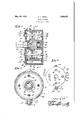
- Fig. 1 is a central vertical sectional view of the invention.
- V Y is a central vertical sectional view of the invention.
- Fig. 2 is an end elevational View of the invention. h
- Fig. 3 is a sectional view taken on line 33 of Fig. 2.
- the invention comprises a cup shaped casing 7 having a tubular projection 8 extending outwardly from one side thereof.
- a filling opening 9 is provided in one side of the casing and normally closed with the plug 10.
- Rotatably mounted in the projection 8 ' is a tubular sleeve 11 which is formed cup shaped and provided with the threaded neck 12, extending outwardly from the tapered portion 13, a nut 14 being threaded on the por tion '12 to secure the sleeve 11 in position in the projection so that the tapered portion13 will effect a liquidtight seal with.
- the projection 8 A flat faced head 15,'eXtends outwardly from theneck 12jwhere'by thesleev.e
- the interior of the sleeve 11 communicates through the openings 16, 16, .17, andl7 with the interior of the casing 7.
- cap 18 is mounted on the casing 7 and cutawayas at 19 to accommodate the axially extending por- U tions on the piston 20whichjis slidably mounted in the casing or housing 7
- the piston 20 l is threaded ontheshaft 21 which'is provided with a socket 22'for'receiving the boss 23 projecting inwardly from the base of the houslng or casing.
- a spring 24 is'co mpressed in the socket 22.
- a cylin'dricalneck 25 projects inwardly from the cap 18 at the center thereof,theshaft'22 at its reduced portion 26 extending through this cylindrical 5 neck.
- each ofthese bolts is provided with a tapered head 32engaging in opening 33 so as to prevent leakage'of liquid therethrough.
- neck 25 pressed firmly in the recess 28 so as to compensate for the wear.
- the housing or casing is mounted by the lugs 39 on either the chassis or the vehicle body and a fiat faced portion 29 of the shaft is connected by a suitable arm in the usual manner, to the other part of the vehicle.
- the sleeve 11 is rotated so as to determine the degree of registration of the openings 16 and 17 with the openings 16 and 17 so that the proper speed of flow of liquid fromone side of the piston to the other side may be effected.
- the shaft 21 Upon relative movement of the chassis and the vehicle the shaft 21 will be rotated thus effecting'movement of the piston 2O axially of the shaft 21 and forcing the liquid from the housing or casing 7 at one side of the pistonto the opposite side of the piston in the housing.
- the piston is normally at such a location on the bolts that the cut away portion 38 is extended through the piston, and as the.
- the use of the sleeve as an adjusting mechanism is one which permits of a very line and quick adj ustment.
- V 1.
- a housing having a pair of spacedopenings formed therein a bypass mounted on said housing communicating through said openings with the interior thereof; a cup shaped sleeve rotatably mounted in said bypass a tapered end on said sleeve; a threaded neck projecting outwardly from said tapered end and extending beyond-said bypass; and a nut threaded on said neck for engaging said end tightly against the end of said bypass to provide a liquid tight seal, said sleeve having spaced openings formed therein for registration with said openings in sa1d housin and rotatrecess for reception of said neck, the base of said recess belng tapered complementary with the beveled edge of said neck; and resilient means for normally pressing the inner edge of sa1d neck 1nto engagement with the base of said recess for effecting a liquid tightconnection.
- a housing having a pair of spaced openings formed therein; a by-pass mounted on said housing and communicating through said openings with the interior thereof; a sleeve rotatably mounted in said by-pass; a tapered end on said sleeve; a portion projecting out- Wardly from said tapered end and extending beyond said ,by-pass; and means cooperating with said portion for engagingsaid end tightly against the end of said by-pass to provide a liquid'tight seal, said sleeve having ing a pair of openings formed therein in rotatably mount'edin said, by-pasaand hav spaced relation to each other and adapted for registration with, said openings in, said housing and communicating with each other sleeve being rotatable on its axis.
- a housing for one'side of said housing; a cylindrical neck projecting inwardly from the inner face of said cap at the center ther of and having its inner edge beveled; a rotatable member projected. through said cap and, extended into said housing and havinga through a passage formed in said sleeve, said
Landscapes
- Engineering & Computer Science (AREA)
- General Engineering & Computer Science (AREA)
- Mechanical Engineering (AREA)
- Fluid-Damping Devices (AREA)
Description
G. A. SHELL SHOCK ABSORBER May 24, 1932.
Filed Jan. 6, 1930 w T Q. Eh 6 A I F 8 V d. w
Patented May 24, .1932 7 h UNITED TE AT NTO FWE sHocK ABSORBER 25 compact and durable in structure.
Application ar a January 6.1930. Serial at, 413,721.
a chassis or similarly situated and operated bodies.
It is an object of the present invention toprovide a device of this class which Will be simple in structure,'economical of manufacture, and highly efiicient in use.
Another object of the invention is the provision of a device which will automatically regulate the resistance. V Another object of the invention is the pro lsvision of a structure whereby a hydraulic shock absorber may be used, and so constructed and arranged as to be leak proofat all times. i
Another object of the invention is the proac vision of a device of this class which will permit of fine adjustments so that the resistance ofi'ered may be regulated.
Another object of the invention is the provision of a device of this class which will be Other objects will appear hereinafter. The invention consists inthe combination and arrangement of parts hereinafter dethe tapered opening 38' formed in. the base of. r
the casing'or 'housing 7. A neck 84 extends inwardly from this b-asearound the cylindrii "cal portion of the bolt 30. The tapered head 32' serves to form a seal with the tapered scribed and claimed.
The invention will be best understood by a reference to the accompanying drawings which form a part of this specification, and in which,
Fig. 1 is a central vertical sectional view of the invention. V Y
Fig. 2 is an end elevational View of the invention. h
Fig. 3 is a sectional view taken on line 33 of Fig. 2.
The invention comprises a cup shaped casing 7 having a tubular projection 8 extending outwardly from one side thereof. A filling opening 9 is provided in one side of the casing and normally closed with the plug 10. Rotatably mounted in the projection 8 'is a tubular sleeve 11 which is formed cup shaped and provided with the threaded neck 12, extending outwardly from the tapered portion 13, a nut 14 being threaded on the por tion '12 to secure the sleeve 11 in position in the projection so that the tapered portion13 will effect a liquidtight seal with. the projection 8. A flat faced head 15,'eXtends outwardly from theneck 12jwhere'by thesleev.e
11 maybe rotated by use of a suitable wrench. i
The interior of the sleeve 11 communicates through the openings 16, 16, .17, andl7 with the interior of the casing 7. cap 18 is mounted on the casing 7 and cutawayas at 19 to accommodate the axially extending por- U tions on the piston 20whichjis slidably mounted in the casing or housing 7 The piston 20 l is threaded ontheshaft 21 which'is provided with a socket 22'for'receiving the boss 23 projecting inwardly from the base of the houslng or casing. I A spring 24 is'co mpressed in the socket 22. A cylin'dricalneck 25 projects inwardly from the cap 18 at the center thereof,theshaft'22 at its reduced portion 26 extending through this cylindrical 5 neck. v The inner end of the neck 25 is cut on a bevel to provide the bevel surface 27 which engages in a recess 28 formedinthe shaft 21. A flat faced portion 29 is formed on thejoutejr end of the reduced portion 26-ofithe shaft'21. Ex
- tending through the housingor casing'are bolts 30 and 31, and each ofthese bolts is provided with a tapered head 32engaging in opening 33 so as to prevent leakage'of liquid therethrough. The cylindrical portion of the 8 bolts also form with thejportion 34 aseal. Projecting inwardly'from the cap are bosses '35snugly fitting the periphery of the bolts and tapered nuts 36 arethread'ed on these 1 bolts and engage in the tapered pockets or recesses 37=formed in the .capso that a double seal is provided in the cap, around each ofthe I bolts. As shown in Fig.1 and Fig. 2 some of. the bolts are cut away as at 38. while others '1 bolts becomes possible.
In operation the housing or casing is mounted by the lugs 39 on either the chassis or the vehicle body and a fiat faced portion 29 of the shaft is connected by a suitable arm in the usual manner, to the other part of the vehicle. The sleeve 11 is rotated so as to determine the degree of registration of the openings 16 and 17 with the openings 16 and 17 so that the proper speed of flow of liquid fromone side of the piston to the other side may be effected. Upon relative movement of the chassis and the vehicle the shaft 21 will be rotated thus effecting'movement of the piston 2O axially of the shaft 21 and forcing the liquid from the housing or casing 7 at one side of the pistonto the opposite side of the piston in the housing. When this movement begins the pistonis normally at such a location on the bolts that the cut away portion 38 is extended through the piston, and as the.
piston moves to this cut away portion, leakage of liquid through the piston, around the This results in a rapid initial movement so that while some resistance to relative movement of the movable parts is effected at the beginning, this resistance gradually increases.
The use of the sleeve as an adjusting mechanism is one which permits of a very line and quick adj ustment.
WVhile I have illustrated and described the preferred form of construction of my invention, I. do not wish to limit myself to the precise details of structure shown but desire to avail myself of such variations and modifications as may comewithinthe scope of the appended claims.
Having thus described my invention, what I claim as new and desire to secure by Letters Patent is: V i
V 1. In a device ofthe class described, a housing having a pair of spacedopenings formed therein a bypass mounted on said housing communicating through said openings with the interior thereof; a cup shaped sleeve rotatably mounted in said bypass a tapered end on said sleeve; a threaded neck projecting outwardly from said tapered end and extending beyond-said bypass; and a nut threaded on said neck for engaging said end tightly against the end of said bypass to provide a liquid tight seal, said sleeve having spaced openings formed therein for registration with said openings in sa1d housin and rotatrecess for reception of said neck, the base of said recess belng tapered complementary with the beveled edge of said neck; and resilient means for normally pressing the inner edge of sa1d neck 1nto engagement with the base of said recess for effecting a liquid tightconnection. v I
3. In adevice of the class described, a housing having a pair of spaced openings formed therein; a by-pass mounted on said housing and communicating through said openings with the interior thereof; a sleeve rotatably mounted in said by-pass; a tapered end on said sleeve; a portion projecting out- Wardly from said tapered end and extending beyond said ,by-pass; and means cooperating with said portion for engagingsaid end tightly against the end of said by-pass to provide a liquid'tight seal, said sleeve having ing a pair of openings formed therein in rotatably mount'edin said, by-pasaand hav spaced relation to each other and adapted for registration with, said openings in, said housing and communicating with each other sleeve being rotatable on its axis. for varying the area of the openings in registratiomone endof said sleeve beingtapered and engageable with a tapered surface in said bypass; and means for forcing the taper of saidsleeve into engagement with the tapered surface of said by-pass to provide a liquid tight seal.
In testimony whereof I have signed the foregoing specification.
GUSTAVE A; i SHELL,
able on its axis for varying the area of open nag-s 1n registration.
2.. In a device of the class. described, a housing; a cap for one'side of said housing; a cylindrical neck projecting inwardly from the inner face of said cap at the center ther of and having its inner edge beveled; a rotatable member projected. through said cap and, extended into said housing and havinga through a passage formed in said sleeve, said
Priority Applications (1)
| Application Number | Priority Date | Filing Date | Title |
|---|---|---|---|
| US418721A US1859995A (en) | 1930-01-06 | 1930-01-06 | Shock absorber |
Applications Claiming Priority (1)
| Application Number | Priority Date | Filing Date | Title |
|---|---|---|---|
| US418721A US1859995A (en) | 1930-01-06 | 1930-01-06 | Shock absorber |
Publications (1)
| Publication Number | Publication Date |
|---|---|
| US1859995A true US1859995A (en) | 1932-05-24 |
Family
ID=23659313
Family Applications (1)
| Application Number | Title | Priority Date | Filing Date |
|---|---|---|---|
| US418721A Expired - Lifetime US1859995A (en) | 1930-01-06 | 1930-01-06 | Shock absorber |
Country Status (1)
| Country | Link |
|---|---|
| US (1) | US1859995A (en) |
-
1930
- 1930-01-06 US US418721A patent/US1859995A/en not_active Expired - Lifetime
Similar Documents
| Publication | Publication Date | Title |
|---|---|---|
| US3955852A (en) | Trailer hub cap device | |
| US1859995A (en) | Shock absorber | |
| US3472484A (en) | Sealing means for valve ports | |
| US2678114A (en) | Shock absorber with adjustable valve | |
| US1636560A (en) | Portable grinding tool | |
| US2615535A (en) | Direct acting friction shock absorber | |
| US1577579A (en) | Motion-transmitting device | |
| US2670816A (en) | Bearing for use in hydraulic shock absorbers | |
| US1373146A (en) | Marking and writing device | |
| US2811397A (en) | Unit for adjusting tracks of crawler type tractors | |
| US1637908A (en) | Lubricating apparatus | |
| US1470931A (en) | Shock absorber | |
| US1445830A (en) | gifford | |
| US1723445A (en) | Vehicle spring-controlling device | |
| US2410539A (en) | Shock absorber structure | |
| US1806286A (en) | Joint | |
| US1046090A (en) | Pneumatic spring for vehicles. | |
| US1870871A (en) | Shock absorber | |
| US1703278A (en) | Lubricating system | |
| US1704258A (en) | Shock absorber | |
| GB367608A (en) | Improvements in shock absorbers | |
| US1215130A (en) | Oil-can. | |
| US1777129A (en) | Coupling for relatively movable members | |
| US1464218A (en) | Fountain pen | |
| US2595668A (en) | Piston reforming tool |