US1859987A - Seaplane runway - Google Patents
Seaplane runway Download PDFInfo
- Publication number
- US1859987A US1859987A US406918A US40691829A US1859987A US 1859987 A US1859987 A US 1859987A US 406918 A US406918 A US 406918A US 40691829 A US40691829 A US 40691829A US 1859987 A US1859987 A US 1859987A
- Authority
- US
- United States
- Prior art keywords
- runway
- seaplane
- members
- caps
- piles
- Prior art date
- Legal status (The legal status is an assumption and is not a legal conclusion. Google has not performed a legal analysis and makes no representation as to the accuracy of the status listed.)
- Expired - Lifetime
Links
- 238000010276 construction Methods 0.000 description 4
- 238000009408 flooring Methods 0.000 description 4
- XLYOFNOQVPJJNP-UHFFFAOYSA-N water Substances O XLYOFNOQVPJJNP-UHFFFAOYSA-N 0.000 description 2
- 238000006066 Comins reaction Methods 0.000 description 1
- 101100180320 Mus musculus Itln1 gene Proteins 0.000 description 1
- 238000004873 anchoring Methods 0.000 description 1
- 239000000463 material Substances 0.000 description 1
- 229920000136 polysorbate Polymers 0.000 description 1
- 230000000284 resting effect Effects 0.000 description 1
Images

Classifications
-
- E—FIXED CONSTRUCTIONS
- E02—HYDRAULIC ENGINEERING; FOUNDATIONS; SOIL SHIFTING
- E02B—HYDRAULIC ENGINEERING
- E02B3/00—Engineering works in connection with control or use of streams, rivers, coasts, or other marine sites; Sealings or joints for engineering works in general
- E02B3/04—Structures or apparatus for, or methods of, protecting banks, coasts, or harbours
- E02B3/06—Moles; Piers; Quays; Quay walls; Groynes; Breakwaters ; Wave dissipating walls; Quay equipment
- E02B3/068—Landing stages for vessels
Definitions
- Another object is to provide a noveljconstruction wherein maximum use -is made of pre-cast and pre-built units to be used, the
- Another object is to'provide a novel construction which is of knock-downtype.l
- Figure 2 is a cross sectional view thereof
- Figure 3 is a detail longitudinal sectional view taken on the line 3 3 of Figure l',
- Figure 4 is a central longitudinal sectional view taken on the line 4 4 of Figure l,
- V Figure 5 is a viewl similar to Figure 3 but taken through'a modied form
- FIG. 7 is a view similar to Figure 3 but' taken through a further modi-fied form,andV
- piles are driven in pairs as' at l2, 13 and-14,
- VThe cap members 15" are atxdifterent elevations according VYto the'bed of the stream and the application of the flooring or slabk Figure 6 is a detail section taken on the line for instance, although f anydesired number andthe angle that the runwayisto assume 28 adapte l ana itis) t be' anaerstaaiat filfaesirea, the. may bev ⁇ filled. in: with4 laround' the stream PIGSQL f v
- the runway properis designated A andhas Vaskeleton frame lmade npo-fwooden or metallicbeams or'inanydesireol'f manner.
- the framef may have Aa plurality of longitudiria-l beams 16l and crossbeatles 17. Di'sposed on top of the beams 1 6 are plates 18, aridon' topV of thellatter 4 are .doveftail-strips4 I9, of
- a modiied form of the invention is shown in Figures 5 and 6.
- the only diiii'erence is in the cap which here is designed 15L and is theequivalent of the cap 15.
- 4Such cap 15EL if ⁇ desired may be made of concrete and in its lower surface it may have a recessV 30 into which the upper lends ofthe piles extend.
- the caps 15a have slotsl'intoq v Y which thek shackles pass.
- a further modified form isgshown in Fig- ⁇ ures 7 and 8 and the difference over the form of Figures 1 and Qresiding in jomitting'plates 18 so that theslabs 22'Vwill rest on the upper surface of beams 16.
- j Y. v l Various changesmay be resorted lto provided they allfwithin thespirit and scope I claim ras my invention v f' 1.
- a runway of the classdescribed'com-y prising, a skeleton Vframe capable of floating,Y ooringapplicable to the frame ofa weight which overcomes itsbuoyancy,4 piles having oaps,said frame resting on saidl caps and y movable thereto kas its buoyancy is, overcome,A and means fto secure the frame to jthe piles comprisinglshackles passing over portions of thefralneand extending through thev caps and secured to the piles.
Landscapes
- Engineering & Computer Science (AREA)
- General Engineering & Computer Science (AREA)
- Environmental & Geological Engineering (AREA)
- Ocean & Marine Engineering (AREA)
- Mechanical Engineering (AREA)
- Civil Engineering (AREA)
- Structural Engineering (AREA)
- Road Paving Structures (AREA)
- Other Liquid Machine Or Engine Such As Wave Power Use (AREA)
Description
o. A. sANDQulsT 1,859,987
SEAPLANE RUNWAY Filed Nov. 13, 1929 2 Sheets-Sheet l May 24, 1932.
May 24, 1932. o. A. sANDQUlsT SEAPLANE RUNwAY 2 Sheets-Sheet Filed Nov.
w @lvm Patented May 24, 1932 oscAn A. sANnQUIs'r, for comin ssntnsrnoarnn 1:Y
sEArANE itUnvvY.
Application inea November 1 19192915 "ser'iai branca-ais@ This invention relates to a runwaycon# struction for seaplanes" and airplanes of the amphibian type.
It is an object of the invention to provide v [5; a construction or lmeans whereby such planes maybe quickly launched or'broug'ht out of the water and in addition to provide a construction wherein theV time required for ini Stallation is reduced-'to a minimum.
Another object is to provide a noveljconstruction wherein maximum use -is made of pre-cast and pre-built units to be used, the
construction enabling most of the assembly ofthe apparatus to take place out of the water 16 be accomplished by sliding movement.
Another object is to'provide a novel construction which is of knock-downtype.l
Various additional objects and advantages will become apparent from a consideration of the description following taken in connection with accompanying drawings` illustrating an operative embodiment.
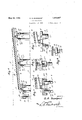
In said drawings Y Figurel is a planview of a runway constructed in accordance with my invention,
Figure 2 is a cross sectional view thereof,
Figure 3 is a detail longitudinal sectional view taken on the line 3 3 of Figure l',
Figure 4 is a central longitudinal sectional view taken on the line 4 4 of Figure l,
VFigure 5 is a viewl similar to Figure 3 but taken through'a modied form,
6 6 of Figure 5,
Y Figure 7 is a view similar to Figure 3 but' taken through a further modi-fied form,andV
view taken: on
piles are driven in pairs as' at l2, 13 and-14,
may beused. Each pair of pilesis surmountthereto.. VThe cap members 15" are atxdifterent elevations according VYto the'bed of the stream and the application of the flooring or slabk Figure 6 is a detail section taken on the line for instance, although f anydesired number andthe angle that the runwayisto assume 28 adapte l ana itis) t be' anaerstaaiat filfaesirea, the. may bev` filled. in: with4 laround' the stream PIGSQL f v The runway properis designated A andhas Vaskeleton frame lmade npo-fwooden or metallicbeams or'inanydesireol'f manner. The framefmay have Aa plurality of longitudiria-l beams 16l and crossbeatles 17. Di'sposed on top of the beams 1 6 are plates 18, aridon' topV of thellatter 4 are .doveftail-strips4 I9, of
lessfgwidththan and centered the plates.` means 20? are adapted? topass through and se'-y cure thei beams 16,517,0*plates 1'8l and strips 119' together: `'lhe forward-lend vof thef'skeleti framefhas an ratnitment strip 21 fastened Vto `withfre'spect to taY Securing bolts or other fasteningV the platesl8` and being flushlwitli vthe strips "The frmefn :may be built en lf'shere@ 'aidg :floated: to thefplace of use or attachment tof In the spacesbetween the; strips the piles.
l59,`f1oor`members 22 are'adaptedto be slid? l in" place, theirend'sbeing` inclined as shownf in FigureZ softhat afdovetailffitwith thestrips'IQi-iesults.' 'The members`22 are independent ofeach other arid for instancemay be` I n'adefof concrete'f although" no limitation as to anyfparticular material ifs te be implied. `Y
After-"the platform is, oated-to the place `'of use, a suitable number of! the flooring lstrips* y, 22Y may be applied Las V'shCwnin Figurel andi Figurer 4f which?` will cause the forward@ 4end Y of the platform to dip-into, the waterwhere-- upon Vthe platform may fbel properly',posi-fv tioned *andi anchored. "When properly'posi- -positiom'sliackle's23' are-placed in straddlifngf 3 relation V"to vthe* bars The ends' "of' thev suitable `means of illumination-is provided? and itlna be electrically illuminated supof the invention. i
ported thereon which lamp has a collar 29' fastened in place by a Wedge 30 interposed betweenv the same andthe pile 27. The globe of the lamp is shown at 31.
A modiied form of the invention is shown inFigures 5 and 6. The only diiii'erence is in the cap which here is designed 15L and is theequivalent of the cap 15. 4Such cap 15EL if` desired may be made of concrete and in its lower surface it may have a recessV 30 into which the upper lends ofthe piles extend. f In addition the caps 15a have slotsl'intoq v Y which thek shackles pass.
A further modified form isgshown in Fig-` ures 7 and 8 and the difference over the form of Figures 1 and Qresiding in jomitting'plates 18 so that theslabs 22'Vwill rest on the upper surface of beams 16. The same reference veharactersare vused asin the form of Figure 1 since the only diii'ere'nce is the omission of theplates 18. j Y. v l Various changesmay be resorted lto provided they allfwithin thespirit and scope I claim ras my invention v f' 1. VA'runway of heclass describeddcom-rl prising av skeleton frame capable of Boating,
flooring applicable to the frame of a weight whichy overcomes its buoyancy, and anchoring means for said flooring into engagement with which it is moved when its buoyancy is over-v come.v Y
2. Arunway of the vclass described comprising Va skeleton framecapable of floating, ilooringapplicable to theframe of a weight which overcomes its buoyancy to move itto applied position, lpileswhaving caps, ysaidframe restingv on r'said caps, and'means to secure theframe tothe piles. 4
3. A runway of the classdescribed'com-y prising, a skeleton Vframe capable of floating,Y ooringapplicable to the frame ofa weight which overcomes itsbuoyancy,4 piles having oaps,said frame resting on saidl caps and y movable thereto kas its buoyancy is, overcome,A and means fto secure the frame to jthe piles comprisinglshackles passing over portions of thefralneand extending through thev caps and secured to the piles.
, J4. Afrunway ofthe class com# prisingfal skeleton frame capable of oating having ,longitudinallyextending dove-.tail
members,-looring members applicablejbewl *Y 'tween said first members, cross members JonV the frame, piles having caps on which the cross'members'rest, said flooringbeing of a weightrgwhich overcomes the 'buoyancyY of the frame so as :to move the'xsa'id Across members into engagement with the caps,` shackles `straddling .the joross members extending throughy the caps, ycollars-carried Vby the' .shackles and* surroundingvf the pilesV gandadapted to be securedthereto. n Y u In testimony whereof II aiixgmy signature.. 3
OSCARY A.- SANDQUISKT.
Priority Applications (1)
| Application Number | Priority Date | Filing Date | Title |
|---|---|---|---|
| US406918A US1859987A (en) | 1929-11-13 | 1929-11-13 | Seaplane runway |
Applications Claiming Priority (1)
| Application Number | Priority Date | Filing Date | Title |
|---|---|---|---|
| US406918A US1859987A (en) | 1929-11-13 | 1929-11-13 | Seaplane runway |
Publications (1)
| Publication Number | Publication Date |
|---|---|
| US1859987A true US1859987A (en) | 1932-05-24 |
Family
ID=23609886
Family Applications (1)
| Application Number | Title | Priority Date | Filing Date |
|---|---|---|---|
| US406918A Expired - Lifetime US1859987A (en) | 1929-11-13 | 1929-11-13 | Seaplane runway |
Country Status (1)
| Country | Link |
|---|---|
| US (1) | US1859987A (en) |
-
1929
- 1929-11-13 US US406918A patent/US1859987A/en not_active Expired - Lifetime
Similar Documents
| Publication | Publication Date | Title |
|---|---|---|
| BR7409621A (en) | A HYDRAULIC CONTROL SYSTEM FOR MAIN USE IN VEHICLES INTENDED FOR HEAVY CONSTRUCTION | |
| US1859987A (en) | Seaplane runway | |
| BR7101956D0 (en) | HYDRAULIC CONTROLLER WITH ROTATING VALVE AND TUBULAR VALVE ELEMENT FOR USE IN THE SAME | |
| US1624900A (en) | Traffic signal | |
| ATA226573A (en) | TRAFFIC SIGN ARRANGED IN THE ROAD | |
| US2579605A (en) | Building of nonpermanent bridges chiefly for military purposes by means of amphibianseaplanes | |
| CH546311A (en) | DEVICE FOR BRIDGING EXPANSION JOINTS IN BRIDGES, ROADS OR SIMILAR TRAFFIC STRUCTURES. | |
| US2369412A (en) | Lattice mat | |
| US1760423A (en) | Tractor toy | |
| GB413773A (en) | Improvements in and relating to elevated centrally pivoted rotating aerodromes or airport landing grounds | |
| BR7304661D0 (en) | MOBILE DEVICE IN THE FORM OF A TILTING RUNWAY FOR ACCESS BETWEEN A VEHICLE AND A PLATFORM | |
| ZAGARELLA et al. | Arresting-gear tests for elevated short takeoff and landing ports(Performance tests of aircraft arresting gear to determine allowable operating restraints on angular displacement and off-center engagements)[Final Report] | |
| US1624325A (en) | Bridge construction | |
| SU18330A1 (en) | Concrete with artificial porous filler material | |
| CH442395A (en) | Device for heating surfaces that are subject to strong mechanical loads, respectively. are exposed to strongly changing weather conditions, such as roads, taxiways, bridges and other traffic areas | |
| RU2046872C1 (en) | Transportable helicopter pad | |
| US1326020A (en) | Airplane landing-platfobm | |
| DK44130C (en) | Device for recording floating bodies, in particular airplanes, on platforms, e.g. Ship decks or landing bridges. | |
| ES105311A1 (en) | A device to establish the union between the lower wings and the fuselage in aircraft. | |
| ES94547A1 (en) | Improvements in propulsion propellers for airplanes, aircrafts and the like. | |
| FR695171A (en) | Vehicle suitable for traversing uneven and submerged terrain, powered by human force | |
| AR204416A1 (en) | HYDRAULIC PUSH CYLINDERS IN PARTICULAR FOR USE ON STEERING AXLES COMMANDABLE BY MOTOR FORCE | |
| BR7400109D0 (en) | RUNWAY DEVICE FOR TRANSFERING PASSENGERS IN AIRPORTS | |
| Yamasaki | Tilted Blocks in the Southeastern Part of Bôsô Peninsula | |
| GB1197600A (en) | Improved See-Saw. |