US1859976A - Health exerciser - Google Patents
Health exerciser Download PDFInfo
- Publication number
- US1859976A US1859976A US413614A US41361429A US1859976A US 1859976 A US1859976 A US 1859976A US 413614 A US413614 A US 413614A US 41361429 A US41361429 A US 41361429A US 1859976 A US1859976 A US 1859976A
- Authority
- US
- United States
- Prior art keywords
- base
- platform
- head
- floor
- machine
- Prior art date
- Legal status (The legal status is an assumption and is not a legal conclusion. Google has not performed a legal analysis and makes no representation as to the accuracy of the status listed.)
- Expired - Lifetime
Links
- 230000033001 locomotion Effects 0.000 description 12
- 230000000284 resting effect Effects 0.000 description 3
- 230000010006 flight Effects 0.000 description 2
- 239000004519 grease Substances 0.000 description 2
- 241000182988 Assa Species 0.000 description 1
- 229920000742 Cotton Polymers 0.000 description 1
- 102100027069 Odontogenic ameloblast-associated protein Human genes 0.000 description 1
- 101710091533 Odontogenic ameloblast-associated protein Proteins 0.000 description 1
- 230000004075 alteration Effects 0.000 description 1
- 229920001971 elastomer Polymers 0.000 description 1
- 230000005484 gravity Effects 0.000 description 1
- VKYKSIONXSXAKP-UHFFFAOYSA-N hexamethylenetetramine Chemical compound C1N(C2)CN3CN1CN2C3 VKYKSIONXSXAKP-UHFFFAOYSA-N 0.000 description 1
- 238000005461 lubrication Methods 0.000 description 1
- 239000000463 material Substances 0.000 description 1
- 230000010355 oscillation Effects 0.000 description 1
- 230000003534 oscillatory effect Effects 0.000 description 1
- BALXUFOVQVENIU-KXNXZCPBSA-N pseudoephedrine hydrochloride Chemical compound [H+].[Cl-].CN[C@@H](C)[C@@H](O)C1=CC=CC=C1 BALXUFOVQVENIU-KXNXZCPBSA-N 0.000 description 1
- 229920006395 saturated elastomer Polymers 0.000 description 1
- 239000007779 soft material Substances 0.000 description 1
- 239000002594 sorbent Substances 0.000 description 1
Images

Classifications
-
- A—HUMAN NECESSITIES
- A61—MEDICAL OR VETERINARY SCIENCE; HYGIENE
- A61H—PHYSICAL THERAPY APPARATUS, e.g. DEVICES FOR LOCATING OR STIMULATING REFLEX POINTS IN THE BODY; ARTIFICIAL RESPIRATION; MASSAGE; BATHING DEVICES FOR SPECIAL THERAPEUTIC OR HYGIENIC PURPOSES OR SPECIFIC PARTS OF THE BODY
- A61H11/00—Belts, strips or combs for massage purposes
- A61H11/02—Massage devices with strips oscillating lengthwise
Definitions
- My invention relates to; health exercisers and'has special reference to the type adapt.
- Another object is the provision of a machine which may be'easily moved aboutwith in the house and placed in inconspicuous or concealed places when not in use. 7
- Fig. 2 is a section on the line Fig. 3 is a section similar to that shown I 2-2 o f Fig. 1 sh owing the means for locking the platform" 7 r p 'fto be described 'An opening 15 may be pro in F l'butgon a somewhat larger scale showlngthe caster arrangement;
- Fig.4 Isa section on the line 4+4: of Fig. 1; t
- Fig. 5 is a sectionon the line 5 5 of Fig.
- Fig.6. is a sectionon the line 6-67 ofFigu Fig. 7 is a section onthe linei-7 "7 of.Fig. 4
- the machine consists generally; of a base arranged to rest upon the fioor and house-the drivingmotor, an operating head' supported from the base'by suitableoiuprights, and'fa platform arranged to movebetween anoper atlve position restingupon' the floor and, an
- the operating head is. driven from the motor in the base bymeans of a belt passing'through.
- Movement -of the platform fromtheinoper- -ativeto the operative position causes there-f traction of the casters letting the machine downs'olidlyyonto the base; Meanjs jare pro-' vided for locking the platform in its. ioperati-ve position.
- a driving motor 22 having a pulley" 23*arranged to drive the belt 24: is supported on the motor board 20. It will be seen that the.
- ledges 19 are so positioned as to support the motor board 20 a very smalldistance from the floor when the base rests upon its lower edge 18, whereby the assembled base possesses a very lowcenter of gravity.
- the platform indicated generally by 25 is provided.
- the platform consists of two parallely disposed sideportions 26 and a top portion 27 having a horizontally" disposed part 28 and aninclinecl part 29.
- the platform may bev covered on its top with a corrugated soft material such asrubber 30, if. desired.
- a crank 33 having an eccentric pin 34 is rotatably positioned in each side of the base 10 through :11 center pin-35 havinga bearing in the side walls of the bases
- the arms 31 are positioned upon the center pins 35 at each side of the base 10 through screws 36, the crank 33 andv center pin 35 being the operator may grasp the platform at the hand'holes 37 and raise it: from the oper-' ative position shown in full lines in Fig. 1
- CIn order to provide a simple and easy way' of moving the machine from place to'place in the house and permit it to be moved to an inconspicuous place;
- a finger knob 46 isrotat'ably positioned in the front wall of the base 10 through a pin 47 fixedly connected to the crank.
- the inner end of the pin 47 is fixedly connected to a I cross-bar 48 which is provided with a crank pin .49 on each end.
- crank pins 49 en-v gage slots 50 and 51 formed on the inner end i of the rods 52 and 53 the rods being posi tioned on substantially the same horizontal center line.
- the 'slot, 50 extends upward from the center line and the slot 51 extends downward therefrom in substantially the crank pins :9 :within the slots 50 and 51.
- Cotter pins 54 maintain the The. rods 52 and 53 are slidably positioned in bearings 55and '56 attached to the front wall of the base 10, and have'their outer ends 57 and-.58slidably'pcsitioned in openings 59 and 60in the side wall of the base 10.
- the crank 45 is turned in a clockwise direction the bar 48 will be similarly turned, thepins 7 ⁇ L9 moving along the slots 50 and 51 and drawing the rods 52 and 53inward, whereby the v ends of thelatter 57 and 58 will be drawn out 7 of the openings 61 and 62 of thearms31.
- a head designated generallyby 65, is positioned on the upper end of the tubular uprights, as shown inFig.
- the lower end of the'head 65 is provided withtwosplit collars 66and-6'Z, the collar 66 a being arranged to'slide over theftop 0f the cylindrical upright'63 andthe collar 67 being arranged to slideover the top of' the upright 64.1
- Each of the collars 66- and 67 are provided with a projection 68 having a ⁇ tappedand threaded opening69 and a pro ection 70 through which the'bolt'7l may-pass.
- the bolt 71 is provided with a shank 72 ar-' ranged to bearagainst theprojection 70 whereby rotation of the bolt'will cause the collar to be drawntogether, tightening the collar about the upper end of the upright 63 or 64.
- the bolts 71 are provided with extensions 7 3 upon which various accessories used with the machine suchias the-strap or belt may be hung, the extensions also serv-' ing as handles to be grasped in moving-the device around.
- Screw threaded sleeves 74 and 75 are positioned about the uprights 63 and 64 near their upper ends and thread thereon as at 76. The collars 66 and 67 slide down over the end of the uprights'63 and 64 until they come in contact with the upper edges of the screw sleeves 74 and75.
- bolts 71 are then tightened, thereby tighten ing the head'65 uponthe uprights 63 and 64.
- the bolts 7 l may be loosened, thereby loosening the head 65 on the uprights '63 and 64.
- the screw threaded sleeves 74and 7 5 arethen turned to raise the head65 to tightenthe belt under the desired tension; 1
- the operating head, 65 which may beadand78, a v shaped front wall 79, and a removable rear wall is positioned upon the uprights 63 and 64 as'already indicated.
- A: web 81 is formed on the inner face'of the head 65 and 'serves to support a bearing 82 within which a shaft 83 is journaled,
- a pulley 84' is fixedly positioned on the rear end of the shaft 83 by means ofa key 85 and nut 86 bearing82 and shaft 83 being so positioned as to support the pulley 84 vertically above the and place it tioned.
- gether" l -P ys 87 and 88' are sup" a 7 5 the front of the operating'head 65 as shownported upon shafts 8.9- and 90 threaded into in-Fig.. 5.2
- the forward end of thevshaft 83 isprovided with a crank 91 and pin 92.
- crank pin 92 has rotatable engagement with I engagement with an offset sleeve- 94, oifset iv a bearing block .93 which inturn has slidable from the center .of rotation of a rocker arm 95.. B'ythis arrangement rotary motion of the shaft 83 will be translated into horizontal oscillating motion at the sleeve 94.
- the rockerarm 95 is positioned in the front 7 91 :of theoperating head'65 in a slot 96..
- Apin 97.passing throughpars 98 and 99 of the front 79, and through the rockerjarm 95, permits the arm to rotate about "itsdcenter atwhich point it is suspended by the pin-97, i
- this base is arranged to rest squarely I 25 iii 'itsflgfyperative' position i is securely fastened to the; base: 10..
- the operator stands Y upon this plat-form. when using the machine a very low center. of 'graIvityf
- A'health exerciser comprising a base
- a health exerciser comprising, abuse '-arranged to normally rest upon the floor, an
- operatinghead adapted to be supported above vporting means connecting said motor and said said base, a motor mounted on a fixed support within said base and having a pulley on its armature shaft, an arm positioned upon said head arranged to be oscillated about a central point, a pulley in said head, means operated by the pulley for oscillating the arm, a i
- a health exerciser comprising, a base arshaft of said motor, an operating head adapted to be supported above said base, anarm positioned upon said headarranged tobe osranged to normally rest upon the floor, a'driv ingmotor mounted on a fixed support in said base, a pulley positionedupon' the armature cillated, means including a pulley positioned in the head for oscillating said arm, a belt connecting said motor pulley and said vlast' namedpulley, at least one tubular upright arranged to support'saidhead upon saidb'ase and enclose said belt, and a sleeve threaded upon said tubular upright serving normally to support the head thereon but also arranged when turned to raise or
- a health exerciser having an operating head, a supporting base adapted to. normally ,restuponthe floor, at least one upright supporting said head upon said base, an oper-Q ating mechanism positioned upon said head,
- a health exerclser having an1operat-j ing head, a base, andmeans'for supporting thehead upon-the base, a pluralitvof caster arms .pivotally positioned intermediate their ends within said base, casters positioned on one end of said caster arms arranged. to be projected and retracted by movement of the opposite ends of said arms, a platform forthel user movable from an extended operative position to a retractedinoperative'position, and: V
- I means operated in such movement of said platform for simul aneously moving the free ends of said caster arms whereby said'casters' aresimultaneously and uniformly-fprojected or retra'cte'd'to move saidbase between its normal position upon the fioor'andaposition supported upon said casters.
- a base having the top front portion thereof formedoutwardly and downwardly inclined relative to the head to serve as one. platform for resting onelfoot of the user or c for the user to stand .upon, and a hinged platform'upon which the user nay'stand ori -estv the other foot, connected to the base and arranged to'move between an operative positionin contact withthe floor in front of the base when in use and an inoperativeposition relative to the head to provide a platform for the user, a second'platform upon WlllCh.
- the user may stand, arranged to move between an operative position in contact with the floor in front of the base in a predetermineddesired relation to the aforesaid plat- 7 form and an inoperative position above the base, and means forpivotally supportlng the platform upon the base.
- a plurality of casters positioned within the base adapted to be moved between a proj ected position wherein the'base is supported thereon and a retracted position wherein the base rests upon the floor, a platform attached i to said base adapted to movebetween an operative position in contact with the floor andan inoperative position above the base, said i'on'the' floor in front of thebase and in a prede- V i platformbeing arranged to permit the user to stand. thereon when in its operative posi ⁇ tion, and means for causing sa1d casters to be 1 i. 13101801366]. when sa1d platform is moved from its operative to its inoperative position and retracted when said platform is moved from its inoperative to its operative position.
- a health exerciser of the character described having an operating head, a base, and means for supporting the head upon the p base, a platform upon which the user may stand, pivotally connected tothe base and arranged to swing between an operative position incontact with the floor infront of the 3 the pivoted bits P i QPOsitio-n; P
- a machine of the-character described 1 comprising a hollow base arranged to" rest" ing the head, a motor mountedinsaid base.
- r 1 comprising; a hollow substantially rectanglexlar base, an upright on the base supporting a pair oflevers pivotallyjinounted 'on eachof thefopposedside walls of thebase carrying icasters on the freeendsthereofapproximate i "ly the four'corners'of the baseyeach pair of levers having their other ends extending a;
- said motor I having detachable con'n'ectionwith the afore said head operating means, and a support for the motor removably secured in the bottom of said tubular supports, said head-being arranged to be adjusted asto elevation with respected to the base whereby'to vary th'e tension ojf th e belt, a'ndme'ans forclamping-the split collar portions on said supports in the adjustedposition of the head, the said means comprising screws for drawingtogethe'r'the split portions of said collars, said screws being elongated at the head portions thereof and extending laterally from, opposite sides of the head and adapted to serve as handles in the transporting of the machine.
- a machine as set forth-in claim 14' ineluding means on the front wall of said base cooperating with at least one ofthe. arms or the pivoted platform for locking said plat- 7 form in rigid relation to the base in the operative position of the platform.
- a machineof the character described comprising in combination'ahollow base the top of which 1s formed suitably to serve as a platform for the user to stand upon, a motor mounted in the base andhaving ap'ulley on the-armature shaft thereof adjacent the rear 1 wallof thebase, apair of tubular head supporting members mounted on the base in parallel relation to one anothenhavingthe two flights of an endless belt extended therethrough for operative connection with said 1 pulley, and a head mounted on the upper ends of said members having a vibrating mem- 17
- a machine as set whereinthe headis slidably received on the upper ends of the tubular supports-,the inachine including sleeves threaded on said supports below the headto support the's'ame thereon, said-sleeves being arranged to be turned in'ei ther direction to increase or deber carried thereon and a pulley for operating'the same disposed therein with the belt I
Landscapes
- Health & Medical Sciences (AREA)
- Epidemiology (AREA)
- Pain & Pain Management (AREA)
- Physical Education & Sports Medicine (AREA)
- Rehabilitation Therapy (AREA)
- Life Sciences & Earth Sciences (AREA)
- Animal Behavior & Ethology (AREA)
- General Health & Medical Sciences (AREA)
- Public Health (AREA)
- Veterinary Medicine (AREA)
- Orthopedics, Nursing, And Contraception (AREA)
Description
M'ay24,1932. M, w, Mc'ARDL-E 1,859,976
HEALTH EXERCISER Filed Dec. 12. 1929 2 sheets-Sheet 2 hasheretofore been known, wherein the driv-v ing motor is placed in the base of the machine 1 which rests upon the 'fioorand wherein a plat- Patented May 24 1932 are r TE MICHAEL QMCARDLE, OFCHICAGQ, ILLIN61$ i I (HE LT EXnnoIsEa Application filed December12, 1929. Serial at. 413,614.
My invention relates to; health exercisers and'has special reference to the type adapt.
form" is provided, movable between an in operative positionabove the base and an operative position into which it is fastened to permit the user to stand thereon, eliminating the necessity of fastening the machine toa suitable support during operation. In the inoperative position of theplatform, the floor space occupied by the machine is substantial- 1y smaller than for other machines havingplatforms. I
Another object is the provision of a machine which may be'easily moved aboutwith in the house and placed in inconspicuous or concealed places when not in use. 7
I have also aimed to'provide a machine which may be economicallymanufactured.
I have further aimed to provide an exer-" ciserh'avii'ig improved means of operating an oscillatingmember characterized by the location of the'motor in the-base and the' provision of enclosed"intermediate'mechanism for. transmitting motion from the base .in its operative position;
to the oscillating member. 7 H V Another object is the provisionv of, improvelf means for producing oscillating m0 tion of the rocker. arm. I
Other objects and attendant advantages will become apparent to those skilledin the art from the following description and the,
accompanying drawings in.which' showing the'base and platform in section, the inoperative position of the platform being shown in dotted lines; V
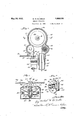
Fig. 2 is a section on the line Fig. 3 is a section similar to that shown I 2-2 o f Fig." 1 sh owing the means for locking the platform" 7 r p 'fto be described 'An opening 15 may be pro in F l'butgon a somewhat larger scale showlngthe caster arrangement;
Fig.4 Isa section on the line 4+4: of Fig. 1; t
Fig. 5 is a sectionon the line 5 5 of Fig.
1 showing the head inlsection;
5 showing the rocker arm and actuating. mechan1sm,and
Fig.6. is a sectionon the line 6-67 ofFigu Fig. 7 is a section onthe linei-7 "7 of.Fig. 4
6 showing a vertical section through the" rocker arm and rocker armfcrank. Pfi- The machine consists generally; of a base arranged to rest upon the fioor and house-the drivingmotor, an operating head' supported from the base'by suitableoiuprights, and'fa platform arranged to movebetween anoper atlve position restingupon' the floor and, an
inoperative position above the base. "The operating head is. driven from the motor in the base bymeans of a belt passing'through.
the supporting upright. Movementof the platform fromthe operative to' the inoperative position causes a .pluralityof casters to be forced out of the base lifting theamachine and pp ng itupon the casters.-
Movement -of the platform fromtheinoper- -ativeto the operative position causes there-f traction of the casters letting the machine downs'olidlyyonto the base; Meanjs jare pro-' vided for locking the platform in its. ioperati-ve position. 1
"Referringnow.to" the drawingsrFigszfl f v.1; to, 4, the numeral 10 indicates generally.the 7 base offlthe 'ma'chinearranged to support the remainder "of the operating. me chanismfi- Whilethisbase may be-of any desired shape I I have found it convenienttogiv'e ita. b'ox* V like 'shape, iii.,order to-completel-y. eove'rfthe 1 motor; and provide its front'top portion with a downwardly inclined face, as .indicate'di at=l1.- If desired,.this fac e 1 1 m'ay:be proa" such as rubber or th'e?like uponlwhichthe;
A driving motor 22 having a pulley" 23*arranged to drive the belt 24: is supported on the motor board 20. It will be seen that the.
In order to provide a place for the user of the machine to stand and to stabilize the machine against forces which will presently become apparent, the platform indicated generally by 25 is provided. The platform consists of two parallely disposed sideportions 26 and a top portion 27 having a horizontally" disposed part 28 and aninclinecl part 29. The platform may bev covered on its top with a corrugated soft material such asrubber 30, if. desired. Side arms 31 attached to .the' platform on either side by means of screws 32, lie along the sides of the base 10 and serve to support theplatform 25 thereon. "A crank 33 having an eccentric pin 34: is rotatably positioned in each side of the base 10 through :11 center pin-35 havinga bearing in the side walls of the bases The arms 31 are positioned upon the center pins 35 at each side of the base 10 through screws 36, the crank 33 andv center pin 35 being the operator may grasp the platform at the hand'holes 37 and raise it: from the oper-' ative position shown in full lines in Fig. 1
.to the'inoperative position shown in dotted lines in the same figure.
CIn order to provide a simple and easy way' of moving the machine from place to'place in the house and permit it to be moved to an inconspicuous place; There arranged to have casters projected downward from [the base I of the machine when the platform is moved from'its operative to its inoperative position.
It should be observed that-in thisoperation' the platform is'mo-ved outjofc'ontact with the fioor'and the castersare simultaneously pro jected from the base, thus-.permitting-the sockets 41 are positioned on the outer end of machine to be rolled along the'floor. Inorder to-accomplish this I have provided caster arms 38, two of which are: attached on each side of the base to pins 39 positionedin the side ofthebase. The caster arms are ajr ranged to rotate about the pins 39 and are held in position by'cotter pins 40., Caster arranged to rotate with rotation'ofthe armssame lane. 31. Itwill be seen that by this arrangement p assa /e the caster arms 38 and arrangedto support casters of any suitable/type indicated generally by 42. Slots 43 having slidable engagement with the eccentric pin3d of the crank '33, are positionedon the innerend of each caster arm. When the platform 25 is rotated from'itsoperative position to its inoperative position the crank 33 will be .rotated moving the eccentric pin 34 to the upper position in slots a3 and raising the inner ends of the caster arms 38. When this occurs the caster sockets 41 will be moved downward projecting the casters 42 through openings 44 in the motor board 20, as shown in dotted lines in Fig. 3; Projection of the casters 42 cause.
the lower edges 18 of the base to be lifted free from thcfloor as indicated in dotted lines in Fig. The whole machine may then be rolled along a level surfaceas will be obvious. I V 7 In order that the platform 25 may serve to stabilize the base 10 and hold it fixedly to the floor under the weight of the user during the operation of the machine, I have provided means for fixedly securing the platform to the base when the'platform is in its operativ-e position. "To this end a crank 45 hav-.
ing a finger knob 46 isrotat'ably positioned in the front wall of the base 10 through a pin 47 fixedly connected to the crank. The inner end of the pin 47 is fixedly connected to a I cross-bar 48 which is provided with a crank pin .49 on each end.
The crank pins 49 en- v gage slots 50 and 51 formed on the inner end i of the rods 52 and 53 the rods being posi tioned on substantially the same horizontal center line. The 'slot, 50 extends upward from the center line and the slot 51 extends downward therefrom in substantially the crank pins :9 :within the slots 50 and 51.
Cotter pins 54 maintain the The. rods 52 and 53 are slidably positioned in bearings 55and '56 attached to the front wall of the base 10, and have'their outer ends 57 and-.58slidably'pcsitioned in openings 59 and 60in the side wall of the base 10. Referring ,to' Figs. 1:and 2,, it will be seen that when the crank 45 is turned in a clockwise direction the bar 48 will be similarly turned, thepins 7 {L9 moving along the slots 50 and 51 and drawing the rods 52 and 53inward, whereby the v ends of thelatter 57 and 58 will be drawn out 7 of the openings 61 and 62 of thearms31. In
like manner when the crank 45- is turned in a counter-clockwisedirection the rods 52 and 53 will be projected outward into the open-.
bemoved over the floor-with ease; 1
While the upright portion ofthe 'machinef. may be of any desired shape I have arranged.
to provide two pipes or tubular members,
indicated generally by 63 and 64,'having their lower ends positioned in thethreaded open-' ings 14 of the base 10, insuch wise as to receive the parallel flights of the belt 24 coming-- from the pulley 23.- A head, designated generallyby 65, is positioned on the upper end of the tubular uprights, as shown inFig.
5. The lower end of the'head 65is provided withtwosplit collars 66and-6'Z, the collar 66 a being arranged to'slide over theftop 0f the cylindrical upright'63 andthe collar 67 being arranged to slideover the top of' the upright 64.1 Each of the collars 66- and 67 are provided with a projection 68 having a} tappedand threaded opening69 and a pro ection 70 through which the'bolt'7l may-pass. The bolt 71 is provided with a shank 72 ar-' ranged to bearagainst theprojection 70 whereby rotation of the bolt'will cause the collar to be drawntogether, tightening the collar about the upper end of the upright 63 or 64. The bolts 71 are provided with extensions 7 3 upon which various accessories used with the machine suchias the-strap or belt may be hung, the extensions also serv-' ing as handles to be grasped in moving-the device around. Screw threaded sleeves 74 and 75 are positioned about the uprights 63 and 64 near their upper ends and thread thereon as at 76. The collars 66 and 67 slide down over the end of the uprights'63 and 64 until they come in contact with the upper edges of the screw sleeves 74 and75. The
The operating head, 65 which may beadand78, a v shaped front wall 79, and a removable rear wall is positioned upon the uprights 63 and 64 as'already indicated. A: web 81is formed on the inner face'of the head 65 and 'serves to support a bearing 82 within which a shaft 83 is journaled, A pulley 84' is fixedly positioned on the rear end of the shaft 83 by means ofa key 85 and nut 86 bearing82 and shaft 83 being so positioned as to support the pulley 84 vertically above the and place it tioned. within-the operating head :65 below the pulley 84 and to each side thereof and serve to direct the belt 24 inwardso that the it two flightsthereof'will operate thehollow' uprights 63 andf64 in substantially parallel mitting' the? uprights to be placed close to-.
gether" l -P ys 87 and 88' are sup" a 7 5 the front of the operating'head 65 as shownported upon shafts 8.9- and 90 threaded into in-Fig.. 5.2 The forward end of thevshaft 83 isprovided with a crank 91 and pin 92. The
crank pin 92 has rotatable engagement with I engagement with an offset sleeve- 94, oifset iv a bearing block .93 which inturn has slidable from the center .of rotation of a rocker arm 95.. B'ythis arrangement rotary motion of the shaft 83 will be translated into horizontal oscillating motion at the sleeve 94. The rockerarm 95 is positioned in the front 7 91 :of theoperating head'65 in a slot 96.. Apin 97.passing throughpars 98 and 99 of the front 79, and through the rockerjarm 95, permits the arm to rotate about "itsdcenter atwhich point it is suspended by the pin-97, i
held in position by means of aset'screw 100. Obviously, oscillating horizontal motion of V I the sleeve 94 will cause oscillating movement of the ends'101 and 102 of the rocker arm;95.; V
A recess 103-is providedlinthetop of the bearing block93 and has an opening 104 to; the; eccentric pin 92. This'recess is arranged;
to hold a quantity of cotton or otherab-f sorbent. material 105 which is saturated with 100 011 whereby constant lubrication. of thebearto be attached to the ends 101 and: 102 ofthe rocker arm-95.: It is through this strap that the oscillating movementof thjeiarm 95 is transferred to the; user: Since; this strap forms no part 'ofmy invention it has not been. described. or illustrated,.suifice it to say that depressions 106 are. provided along the-rocker to be attached at different distances from the lug isass'ured. A strap. orx bandywhich is l passed-around the body of the user is adapted a center 97'to Varythe throw of each oscillation, In use'the strap. applicator is wrapped: about a certain part of thebody. The user then draws away from the ma chine placing a, tension on the strap whereby the oscillatlons are 't'ransmittedto the body.-;
' Manifold advantages of my improvedcon- I V I I structionwill have become-apparent. The
greater partofthe weight of the machi'ne lies within'the confines ofthe base 10; .plnopera. threaded on the-rear end of thexshaft 83, the
tion, this base is arranged to rest squarely I 25 iii 'itsflgfyperative' position i is securely fastened to the; base: 10.. The operator stands Y upon this plat-form. when using the machine a very low center. of 'graIvityf The platform I:
arm to permit theends ofband or applicator, a I i andconsequeutly holds'the, Wholemachine down upon thefloor so that great strain im- V.
posed upon the enos lOl 3116.102 of the arm 95 do not tip the machineover. In some uses of themachme one foot of the operator will be placed-upon the platform 25 and'one 1 foot upon the inclined of the base, thus "throwing the full Weightof the body. backward inst the applicator. It will be clear tl at even in this position a portion of the bodys weight rests on the platformand base and prevents the tension on the arn'r 95 from tippingthemachineover. l loweverpvhenthe machi evis not'in use the lever 15 is rotated,
" releasing the platform 25 which may thenv be; raised toits inoperative position. When this is done the casters 42 are automatically ing thebelt. It Will be seen that because of the .motor being positioned Within the base otherwise possible.
10, it-is possible to suhstantially reduce the size of the operating head 65 beyond that All of the moving parts of the' machine with the exception of the arm 95 are completely enclosed; There are no exposed parts from, which the user may contract grease or dirt. Parts normally dangerously attractive to children such 'as the bolt 24, are completely enclosed. "It should be observed that a large percentage of the users of these machines are a H women who employ them in the home to keep theirweight: down. In many instances their duties involvethe care of children, which must be done, among other times, when the machines are in use.
as Well a'stopresent no point-from which they collect dirt and grease.
'lVhil-e I havethus described and illus- H trated a specific embodiment of 'my lllVQYl.
" out tion I am aware that numerous alterations? and changes may be made therein, Without materially departing from the spirit of the lnvention and I do not wish to be limited except as requiredby theprior art and the scope of the appended claims, in which I claim-z 1. A'health exerciser comprising a base,
7 arranged to rest upon the floor and having its topiormed to serve as a platform for the user, a head, an arm adapted "to be oscillated, positioned upon said head, hollow upright mean sextending upwardly from the base for supporting said head upon 'saidbase with the armdisposed ina predetermined desired relation tothe platform, amotor positioned with- It is, therefore, -im-' portant that such a machine be so constructed. as to be harmlessto children playing about in said base and enclosed thereby, and means extending through said hollow upright 'sup arm totransmit motion thereto.
,2. A health exerciser comprising, abuse '-arranged to normally rest upon the floor, an
operatinghead adapted to be supported above vporting means connecting said motor and said said base, a motor mounted on a fixed support within said base and having a pulley on its armature shaft, an arm positioned upon said head arranged to be oscillated about a central point, a pulley in said head, means operated by the pulley for oscillating the arm, a i
belt passing over said pulleys, at least one vertically positioned tubular upright ar ranged to support said head upon said base and enclose said belt, andmeans for adjusting the elevation of thehead relative to the base whereby thetension on said belt maybe varied. j V 1 2 3; A health exerciser comprising, a base arshaft of said motor, an operating head adapted to be supported above said base, anarm positioned upon said headarranged tobe osranged to normally rest upon the floor, a'driv ingmotor mounted on a fixed support in said base, a pulley positionedupon' the armature cillated, means including a pulley positioned in the head for oscillating said arm, a belt connecting said motor pulley and said vlast' namedpulley, at least one tubular upright arranged to support'saidhead upon saidb'ase and enclose said belt, and a sleeve threaded upon said tubular upright serving normally to support the head thereon but also arranged when turned to raise or lower said head upon said upright and accordingly adjust the tension' of the belt;
4;. A health exerciser having an operating head, a supporting base adapted to. normally ,restuponthe floor, at least one upright supporting said head upon said base, an oper-Q ating mechanism positioned upon said head,
and a motor arranged to drive saidmechw nism,one or more transporting members positioned in said base,a platform for the user movable from an extended operative position to a retracted inoperative position, and means operated in such movement of said platform forprojectmg said members from said'bas'e whereby said base is lifted. fromlits normal position in contact with the floor andsup-s ported upon said'transporting members to permit easy movement of the health exerciser from place to place. I
5. In a health exerclser having an1operat-j ing head, a base, andmeans'for supporting thehead upon-the base, a pluralitvof caster arms .pivotally positioned intermediate their ends within said base, casters positioned on one end of said caster arms arranged. to be projected and retracted by movement of the opposite ends of said arms, a platform forthel user movable from an extended operative position to a retractedinoperative'position, and: V
i it
I means operated in such movement of said platform for simul aneously moving the free ends of said caster arms whereby said'casters' aresimultaneously and uniformly-fprojected or retra'cte'd'to move saidbase between its normal position upon the fioor'andaposition supported upon said casters. y c
6. In a health exerciserhavingan ,operatinghead, and means, for supporting the head .upon a base having the top front portion thereof formedoutwardly and downwardly inclined relative to the head to serve as one. platform for resting onelfoot of the user or c for the user to stand .upon, and a hinged platform'upon which the user nay'stand ori -estv the other foot, connected to the base and arranged to'move between an operative positionin contact withthe floor in front of the base when in use and an inoperativeposition relative to the head to provide a platform for the user, a second'platform upon WlllCh.
the user may stand, arranged to move between an operative position in contact with the floor in front of the base in a predetermineddesired relation to the aforesaid plat- 7 form and an inoperative position above the base, and means forpivotally supportlng the platform upon the base. V
8; In a health exerciser of the character described having an operating head, abase,
and means for supporting the headupon the. v V I over. the base to an operative positi on V resting.
base, a plurality of casters positioned within the base adapted to be moved between a proj ected position wherein the'base is supported thereon anda retracted position wherein the base rests upon the floor, a platform attached i to said base adapted to movebetween an operative position in contact with the floor andan inoperative position above the base, said i'on'the' floor in front of thebase and in a prede- V i platformbeing arranged to permit the user to stand. thereon when in its operative posi{ tion, and means for causing sa1d casters to be 1 i. 13101801366]. when sa1d platform is moved from its operative to its inoperative position and retracted when said platform is moved from its inoperative to its operative position.
9. In a health exerciser of the character described having an operating head, a base, and means for supporting the head upon the p base, a platform upon which the user may stand, pivotally connected tothe base and arranged to swing between an operative position incontact with the floor infront of the 3 the pivoted bits P i QPOsitio-n; P
base when in use andan inoperative'position above the basewhen notin use, and means for fastening the platform in its operative posi tion' whereby to prevent relativemovement between the base, and platform and prevent? tipping-of the device. I, J- r "fl 10. In ahealthfexerciser of, the character described, having an operating head, a base, and means for supporting the head upon the base,-a plurality of casters positioned within' the base adapted to be moved between apijo jected position whereinthe base is'suppo'rted thereon and aretracted position wherein the base'rests upon the floor, a platform. attached to said base adapted to move between an oper ative position in con-tac't ;wit h".the floor in front of the base and an inoperative position above the base, said platform being arranged;
permitusertostand thereon when in its operative position, means for causing said casters to be pro ected when said platform is moved from its operative to its inoperativepositionand retracted when saidplatformis I moved from its; inoperativeto,.itsf'operative position, and means for locking said plat-= formin its operativejpositionq 1 11. A machine of the-character described 1 comprising a hollow base arranged to" rest" ing the head, a motor mountedinsaid base.
'uponthe, floor, an operating, head abovethe base, a hollow; support extending upwardly" :from the rear portion of the basefor support below the hollow support,;means extending upwardly from the motor: through the hollow" support tothe head totransmit drive tothe latter,- said, base havingTthe; rear ,portion thereof highenough to'provide enclosure f J for the 'motor'but having the fronttop poriform for the user to stand upon or resta foot} base to swingfrom an. inoperativeposi tion on the floorfin fro'nt of, theibaselan d in apre eluding "a platform .pivotally mounted on the base to. swing from an inoperative. 'po 'sition over the base to an operative-position resting.
termined relation to the inclined platform provided on the latter, and ineansforlocking l j i I atform the base in head for operating an, exerciser applicator, a
tion inclined downwardlytofiserveas a plate I 105 12.- A machine as set. forth in claim'll in.- v r j eluding aplatformpivotally mounted on the 14. In amachine-of the character described r 1 comprising; a hollow substantially rectanglexlar base, an upright on the base supporting a pair oflevers pivotallyjinounted 'on eachof thefopposedside walls of thebase carrying icasters on the freeendsthereofapproximate i "ly the four'corners'of the baseyeach pair of levers having their other ends extending a;
"ward each other, a platform having arms reaching alongside the base andpivot'edto the 'side walls thereof-to permit Swinging movea nientofule'plat from a P'OQtionTesfing on the floor in front ofthebase' to a raised inoperative position over the base, and means hit-V111 connection with the ad oi-nin ends'of each pair of levers at theopposite sides ofthe I base for communicating oscillatory move 1o ment to said levers in the swinging movement of the platform to raised positiomwhereby to pro ect the casters on the levers below, the
plane of thebase, so that the casters assume levers on the adjacent side walls, said motor I having detachable con'n'ectionwith the afore said head operating means, and a support for the motor removably secured in the bottom of said tubular supports, said head-being arranged to be adjusted asto elevation with respected to the base whereby'to vary th'e tension ojf th e belt, a'ndme'ans forclamping-the split collar portions on said supports in the adjustedposition of the head, the said means comprising screws for drawingtogethe'r'the split portions of said collars, said screws being elongated at the head portions thereof and extending laterally from, opposite sides of the head and adapted to serve as handles in the transporting of the machine.
In witness of the foregolng nature.
of the base and constituting closure for the Y 7 open bottom of'said'baseu 16. A machineof the character described comprising in combination'ahollow base the top of which 1s formed suitably to serve as a platform for the user to stand upon, a motor mounted in the base andhaving ap'ulley on the-armature shaft thereof adjacent the rear 1 wallof thebase, apair of tubular head supporting members mounted on the base in parallel relation to one anothenhavingthe two flights of an endless belt extended therethrough for operative connection with said 1 pulley, and a head mounted on the upper ends of said members having a vibrating mem- 17 A machine as set whereinthe headis slidably received on the upper ends of the tubular supports-,the inachine including sleeves threaded on said supports below the headto support the's'ame thereon, said-sleeves being arranged to be turned in'ei ther direction to increase or deber carried thereon and a pulley for operating'the same disposed therein with the belt I operatively engaging the same.
forth in claim 16,
crease the tension of the belt by adjusting the elevation of the head as a whole with respect to the base. Y
.18," A machine as set forth in claimb 16 wherein the 'head has two split collar portions slidably adjustable on thenpper ends of said tubular supports, said head being ar-' ranged to be adjusted as to elevation with respect to the base'wh'ereby to varythe tension ofthe belt, and means for clamping the split collar portions 011" said supports in the adjusted position of the head.
19. A achine as set forth in' 'cl'aim 16 I wherein the head has twojsplit collar portions slidably adjustable on the upper ends JMIGHAEL w. McARDLE. Y
Priority Applications (1)
| Application Number | Priority Date | Filing Date | Title |
|---|---|---|---|
| US413614A US1859976A (en) | 1929-12-12 | 1929-12-12 | Health exerciser |
Applications Claiming Priority (1)
| Application Number | Priority Date | Filing Date | Title |
|---|---|---|---|
| US413614A US1859976A (en) | 1929-12-12 | 1929-12-12 | Health exerciser |
Publications (1)
| Publication Number | Publication Date |
|---|---|
| US1859976A true US1859976A (en) | 1932-05-24 |
Family
ID=23637932
Family Applications (1)
| Application Number | Title | Priority Date | Filing Date |
|---|---|---|---|
| US413614A Expired - Lifetime US1859976A (en) | 1929-12-12 | 1929-12-12 | Health exerciser |
Country Status (1)
| Country | Link |
|---|---|
| US (1) | US1859976A (en) |
-
1929
- 1929-12-12 US US413614A patent/US1859976A/en not_active Expired - Lifetime
Similar Documents
| Publication | Publication Date | Title |
|---|---|---|
| US3674155A (en) | Tool storage device | |
| US1709410A (en) | Kinesitherapy apparatus | |
| US1899255A (en) | Exercising machine | |
| US3013287A (en) | Floor polisher | |
| US1859976A (en) | Health exerciser | |
| US2167386A (en) | Clay-working machine | |
| US2457984A (en) | Floor nailing machine | |
| US2401002A (en) | Machine for working wood and the like | |
| US1969247A (en) | Exerciser | |
| US3184190A (en) | Workshop tool stand | |
| US1975382A (en) | Exercising apparatus | |
| US1573998A (en) | Stone gatherer | |
| US2655376A (en) | Skipping bar | |
| US1089801A (en) | Fracture-box. | |
| US1803297A (en) | Wringer | |
| US1320808A (en) | Clamp-machine | |
| US1696609A (en) | Clothes returner for ironing machines | |
| US1808824A (en) | Garment bagging machine | |
| US1608965A (en) | Power table frame | |
| US2229618A (en) | Centrifugal casting machine | |
| US3283856A (en) | Tobacco lifting machines | |
| US1600619A (en) | Sawing machine | |
| US1191243A (en) | Bag-filling machine. | |
| US1949148A (en) | Mattress tufting machine | |
| US1858922A (en) | Massaging apparatus |