US1859971A - Apparatus for icing layer cakes - Google Patents
Apparatus for icing layer cakes Download PDFInfo
- Publication number
- US1859971A US1859971A US307415A US30741528A US1859971A US 1859971 A US1859971 A US 1859971A US 307415 A US307415 A US 307415A US 30741528 A US30741528 A US 30741528A US 1859971 A US1859971 A US 1859971A
- Authority
- US
- United States
- Prior art keywords
- head
- frosting
- cake
- icing
- cakes
- Prior art date
- Legal status (The legal status is an assumption and is not a legal conclusion. Google has not performed a legal analysis and makes no representation as to the accuracy of the status listed.)
- Expired - Lifetime
Links
- 239000000463 material Substances 0.000 description 37
- 239000010410 layer Substances 0.000 description 17
- 238000003892 spreading Methods 0.000 description 7
- 229910052782 aluminium Inorganic materials 0.000 description 3
- XAGFODPZIPBFFR-UHFFFAOYSA-N aluminium Chemical compound [Al] XAGFODPZIPBFFR-UHFFFAOYSA-N 0.000 description 3
- 238000009877 rendering Methods 0.000 description 3
- 230000001360 synchronised effect Effects 0.000 description 3
- 235000005749 Anthriscus sylvestris Nutrition 0.000 description 2
- 229910052751 metal Inorganic materials 0.000 description 2
- 239000002184 metal Substances 0.000 description 2
- 238000000034 method Methods 0.000 description 2
- XUKUURHRXDUEBC-KAYWLYCHSA-N Atorvastatin Chemical compound C=1C=CC=CC=1C1=C(C=2C=CC(F)=CC=2)N(CC[C@@H](O)C[C@@H](O)CC(O)=O)C(C(C)C)=C1C(=O)NC1=CC=CC=C1 XUKUURHRXDUEBC-KAYWLYCHSA-N 0.000 description 1
- 229920002160 Celluloid Polymers 0.000 description 1
- 241001255830 Thema Species 0.000 description 1
- 229910052729 chemical element Inorganic materials 0.000 description 1
- 238000004140 cleaning Methods 0.000 description 1
- 239000011248 coating agent Substances 0.000 description 1
- 238000000576 coating method Methods 0.000 description 1
- KUNSUQLRTQLHQQ-UHFFFAOYSA-N copper tin Chemical group [Cu].[Sn] KUNSUQLRTQLHQQ-UHFFFAOYSA-N 0.000 description 1
- 238000000151 deposition Methods 0.000 description 1
- 230000000694 effects Effects 0.000 description 1
- 238000005461 lubrication Methods 0.000 description 1
- 150000002739 metals Chemical class 0.000 description 1
- QVRVXSZKCXFBTE-UHFFFAOYSA-N n-[4-(6,7-dimethoxy-3,4-dihydro-1h-isoquinolin-2-yl)butyl]-2-(2-fluoroethoxy)-5-methylbenzamide Chemical compound C1C=2C=C(OC)C(OC)=CC=2CCN1CCCCNC(=O)C1=CC(C)=CC=C1OCCF QVRVXSZKCXFBTE-UHFFFAOYSA-N 0.000 description 1
- 239000002356 single layer Substances 0.000 description 1
- 238000009987 spinning Methods 0.000 description 1
- 238000005507 spraying Methods 0.000 description 1
- 239000002699 waste material Substances 0.000 description 1
Images

Classifications
-
- A—HUMAN NECESSITIES
- A21—BAKING; EDIBLE DOUGHS
- A21C—MACHINES OR EQUIPMENT FOR MAKING OR PROCESSING DOUGHS; HANDLING BAKED ARTICLES MADE FROM DOUGH
- A21C15/00—Apparatus for handling baked articles
- A21C15/002—Apparatus for spreading granular material on, or sweeping or coating the surface of baked articles
Definitions
- This invention relates to, a devicejfor depositing and spreading icing orfilling on cakes and the like.
- the object of this-invention is to provide apparatus for automatically distributing frosting on cakes";
- a further objeot ofi the invention is to;
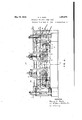
- FIG. 1 is a plan view of a table showing the arrange-' ment of means for filling and icing cakes
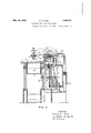
- Figure 2 isa"fragmental front elevation of thetable and the two operatingheads of the device
- FigureB is a rear elevation of the machine
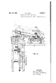
- Figure 4 is a sectional view through the machine, taken on the line/1+4 of Fig. 3
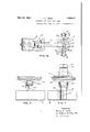
- Figure 5 is an enlarged sectional view taken on the line 55,Fig.
- Figure 6 is an enlarged plan view of the icing head andits supporting means;
- Figures9, 10, and 11 are views similar to Figs; 5, 6, and 8 respectively, showing a modified arrangement of the .head fonfrost-
- the reference numeral 1 denotes a" table on which the operative elements; of thema ator handles them during the filling and icing process, and a belt?) servesrto remove the completed cakes.
- a'pipe' L17 Connected by a'pipe' L17 to said tank is a plunger pump 8 which,"assisted'by* thehead 6a, removes the'filling material-from the tank 6 and-forces it to the head 4 through the flexiblepipe line 9.
- valve 10 ispo'sitioned illus ⁇ , trated to control the flow' of the said material valve :10 and the plunger of the pump '8 are operated by the double track cain 11,"and this allows a simple adjustment of the cam engaging link 12 on the plunger rod 13 to properly 05 synchronize themovement of the said valve and plu'nger
- the rod 1Oaridesthecam 11 and serves to throw-the valve 10,
- the said adjustment 111 also establish theqtravel rof the pump plunger, Whichinturn; determines ash from thetank 6 to ,thenhead'f'j. Both; the 9 the amount of material expelled from the head 4.
- thesaid shaft is driven by means of a sprocket wheel 15 meshing with sprocket chain 16. Motion is transmitted to the said chain through mechanical connec-' tion, such as sprocket wheel 150:, to the revolving shaft 50 which is driven bya belt 51 coming from a suitable source of power.
- this shaft is belted, or rotatably chain connected, to the shaft 24; of the endless belt conveyor 2.
- a long chain or belt 52 serves to transmit the rotation of shaft '50 to the driving'elements of head 5. That is,
- the tubular arm 17 supports the. head 4, and it is fixed to a frame 18 which is mounted to slide vertically in the frame 19..
- the latter frame is fixed to the table 1. Normally the position of the' head israised, as shown in dotted lines in Fig. 4,
- the lowering of the said head is accompanied ,by the engagement of the two'clutch me'mbers'24 and 26, and this engagement causes the pulley 23 to revolve which, olue to the driving belt 32 imparts a spinning movementto the head 41approxi
- the structure of the two heads 4 and 5 is very similar, the chief distinction being that theicing'head 5 has one-or more vertical spreading strips withwhich to ice the sides of the cake. After the filling head 4 has completed its operation, another layer of cake is, superimposed on the cake layer A.
- the Snap'd cake B is "then placed beneath the icing head 5 which isshownin detail in Fig tires 5, 6, and 7. i 1
- the structure of the-head is unique inop'eration'; the structure-is furtherdesirable in; that it is readily taken down for cleaning.
- the icing flows through the tubular arm 17 to the space 176; above the rotary portion ofthe head. .It is preferableto form the entire mechanism of aluminum; but as aluminum does not slide-well'on aluminum unless an abundance .of oil is used, 311619348 01]. cannot be used near the icing or. filling material, it
- a bronze ring 33 is arranged on the arm 17 whereit abuts asteel Q ring 346 fixed'to. rotary .portion 34*of' the head 5-.
- These-two rings of unlike metals may bedrawn into close. engagementand will revolve with little or no lubrication. This serves togive a tight j ointure between the sta- 'tionary and rotary wportionsv of athe head proper, and no leakage of the filling or icing material occurs.
- -A shaft 35 having athreaded engagement with the head portion 34, 'ex-.
- the wing nutor hand wheel 37 may be tightened after the .desired tightnessbetween the fixed and. rotatable membersof the head hasv been obtained. by rotating the plate 361-Thet tworaces of ball bearings 55'and 56,'positioned as'shown,
- the parts, as'seen, may be easily disassembled for cleansing.
- the head portion legs 34a and 34b, and at-theouter end ofeach leg is a circular aperture.forthe reception of 1 tube members 38 and 39 respectively:
- Suitable means,'such as clamps 40, may be em- 34 includes two hollow ployed to retainthe members'38: and 39 in place. It will be noticedithat the interior of the arm 17 and the two legs34a and 34b, and
- the side or end tubes 38 and 39 present a con- 'tinuous opening in which the. icing material rests;
- the pipes leading from thesupply tankjand pump, and the hollow regions last mentioned, are completely filled with frosting before the head ejects anymaterial; on thecake.”
- res1l ient spreading members are preferably composed ofawhighly flexible material, such as high grade rubber, celluloid strips, or a relatively stifiifabric.” As their function is to distributeevenly the icingmaterial depositedon the cake, they must be. very. resilient in order to follow the general contourlofthe cake sur face. Asseen in Fig. "8 of the drawings, the
- strips 41 and 42 are desirably fixed to the por tions 34a and 34bby means of screws 47 and wing nuts 48.
- the portions 41a? and 42a of the strips 41 and 42 have'slots 49"tl1rough which the screws 47fpass, and on the 4 under side of said portions'the metal strips 50 having slots 51 serve as a washer for the several wing nuts 48; As may readily be seen, the
- .edge 52 of the strips 41 and 42 may be moved to cover part ofthe openings 45. Thi's'serves as a means for adjusting the cross sectional area of said openings 45. When aifrosting of A less viscosity is being used the members-4l and 42 may bemoved to cover aportion'of the orifices 45, and in this'way the proper amount of material'may be made to flowtherefrom.
- the openings are shown herein as a plurality of -orifices which needinot'of'necessity be a1igned,b1j1t the'usef wot a divergent slot may probably be employed as an equivalent.
- Orifices .46 in the vertical members 38 and 39 allow the icingmaterial to reach thc sides of cake, 'I
- the orifices in'fthe I member are vertically spaced between the pathsgenof the cake when the headrotates and emits 'erated. by the orifices in themember 39. This allows theicing to'completelyco-verltheslde 1 V A said icingmaterial. As previously explained.
- theicing material is pumped into'the'hollow regionsot the headandits member 34a,34b, 38,.and'39, f v p a "on table 1, the head lowers as the plunger and when a cake B is placed under the head moves to effect the ejecting of the desired members 241and26 are engaged to rotate the said head during the time the frostingis be-g ing ejected, an'dthe spreading strips servejto 'evenly distributethefrostingl" f
- the head 4-whichis used to pertormithe I fillingqoperation is practically, the same as v the head 5.
- the clutch a
- the head portion(SQ hasthe same general shape as the'head
- the orifices'of the'lat'-' head'allowedto'remain in its'loweredopera- 'ter are replaced 7 by a 10562 which eiitends across the two legs GOaYand'GOQ andfit isof in close alignment in place] of the slot, "but either the orifices or the lilfi' 62 should be r ed strips 68 as shown in Fig. 11'.
- Fig. 11 shows the cake D passed half way under the head portion 60 and shows how the frosting 68 is smoothed uponthe cake, 'What. I claim is:
- a machine for frosting cakes and the like'a rotary head serving as a. reservoir for frosting, driving means for rotating the 'same, said head-having orifices therein to emit I frosting material, and feeding means for 1ntermittently supplying'said material to the head, together with synchronized means for to, said head having orifices therein, the areas rendering said head-driving means and said 2.
- driving means for rotating the 'same said head-having orifices therein to emit I frosting material
- feeding means for 1ntermittently supplying'said material to the head, together with synchronized means for to, said head having orifices therein, the areas rendering said head-driving means and said 2.
- a rotary head serving as a reservoir for 1 frosting,'means for rotating the same, saidhead having opemn'gs therein, thevarea of said openings increasing in area propor- I tionat ely to their distance from their center of rotation, and means to. automatically supply frosting to the head and thereby expel it from saidopening at fixed intervals.
- a rotary head serving asa reservoir for frosting, means for rotating "the same, said head having orifices therein to emit fr0st-' ing material, and flexible spreader strips arranged to rotate with said head.
- said head having orifices thereinsto emit frosting material, a tank for frosting material,la pump ,aflixed to said tank, a control valve in said pump, pipe connections from said pump to said operating head, driving means for rotating said head, feeding means for forcing frosting material fromsa'id tank to said head, together with synchronized means *for rendering said head-driving means and said feeding means effective.
- a rotatable head mounted vertically slidable thereon, said head zhaving orifices therein to emit frosting .material, a container for frosting material, .tubular connections between said head and said contamer, means-for feeding .the said materlal 7 from' the container to the said head, automatie'means for lowering the head into operative position, and mechanical elements to rotate the said-head inits lowered position, together'with synchronized means for rendering said feedingmeans, said automatic means, and said'mechanical elementsefliec;
- automatlc means for loweringrthe head into operative position, and mechanical elements to rotate the said head in its lowered position.
- arotatablehead mounted there on, said head having orifices therein, the areas of said orifices increasing in proportion to their distance from their center of rotation, flexible spreader strips arranged on the said head to brush the cake,'accont'ainer for frost- 3 ing material, means for feeding said imaterialto the said head, andjmechanical ele ments to rotate head.
- a table,- conveyor belts operatively ar 7 ranged at each end thereof, a tank to contain filling mate-rial, connections from said tank to a rotatable'head mountedvertically slidabled on said table, afsecond tank to contain icing material, connections from'said tank to a second rotatablelhead mounted verti- Cally slidable on said table, means,for lowering said ,headsinto operative position, means I for rotating thesame in their lowered position, and adjustable meansto feed the material from.
- tubular side members In a head for frostingcakes and the a like a rotary head, tubular side members .7
Landscapes
- Life Sciences & Earth Sciences (AREA)
- Engineering & Computer Science (AREA)
- Food Science & Technology (AREA)
- Confectionery (AREA)
Description
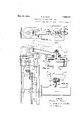
May 24, 1932. H. E. KECK APPARATUS FOR ICING LAYER CAKES Original Filed Sept. 21, 1928 6 Sheets-Sheet INVENTUR Harry' E ,Kec k by a ZJ 4MU his afforneg May 24, 1932. H. E. KE CK 1,859,971
APPARATUS FOR ICING LAYER CAKES Qriginal Filed Sept. 21, 1928 6 Sheets-Sheet 2 FIE-2.13.
IN VE N TOR his af-forneg.
May 24, 1932. H, E, KECK 1,859,971
' APPARATUS FOR ICING LAYER CAKES originalFiled Sept. 21, 1928 6 Sheets-She et 3 I l I I I FIG..4.
IN VE N THE Ham, E. Keck his attorne May 24, 1932. HIE KECK 1,859,971
APPARATUS FOR ICING LAYER CAKES Original Filed Sept. 21, 1928 6 Sheets-Sheet 4 2 FIG. 5.
L [I i INVENTUR MN Harn E- Keck bq 144mm 45 40% his attorney May 24, 1932.
H. E. KECK 1,859,971
APPARATUS FOR ICING LAYER CAKES Original Filed Sept. 21,1928 6 Shets-Sheet s INVEN TOR .3 Harry E- Ke K his aftormez May 24, 1932. H. E. KECK APPARATUS FOR ICING LAYER CAKES Original Filed Sept. 21, 1928 6 Sheets-Sheet 6 MK m J. .m #5 m 4 h S a f fag Patented May 24, 1 932.
rarer oF iee HARRY EL xnck, or rr'rrsnnnen, rnnnsvnvmn J i '7 APnARArUs FoR Ic NG'LAYEn. crimes n Application filed Se tember 21,1928, Serial No. 307,415; vmm ma September 26,1931,
This invention relates to, a devicejfor depositing and spreading icing orfilling on cakes and the like. a
Inorder to obtain an icing that will properly -fiow through spraying nozzles for automatic application to the} surface of a cake, it is'ne'cessarythat the icing be a -boiled icing. Filling; material, used 'between two or; more layers of cake, is generally very viscous, and forthis reason has never been satisfactorily distributed on cakes by the use of automatic machines. Heretofore, it has been necessary to spread filling material, or uncooked frosting vby hand,and it has been found that this method resultsin a great waste of material and labor. The object of this-invention is to provide apparatus for automatically distributing frosting on cakes";
A further objeot ofi the invention is to;
provide an apparatus which will deposit filling material on a cake layeryand which will thereafter distribute assembled layer cake.
frosting on the In the accompanying drawings Figure-l is a plan view of a table showing the arrange-' ment of means for filling and icing cakes Figure 2 isa"fragmental front elevation of thetable and the two operatingheads of the device; FigureB is a rear elevation of the machine Figure 4 is a sectional view through the machine, taken on the line/1+4 of Fig. 3;; Figure 5 is an enlarged sectional view taken on the line 55,Fig. 1, showing to advantage the detailed structure of the icing head Figure 6 is an enlarged plan view of the icing head andits supporting means; Figure 7 is .an end elevation of the same, the rotary head portion'is turned through a 90degree angle from the position shown in ig-.-6-;2Figure8 is a sectional viewthrough the rotary apart 7 ofthe head ,.takenon the line :8 8,Fig.;6";
ing' square cakes.
and Figures9, 10, and 11 are views similar to Figs; 5, 6, and 8 respectively, showing a modified arrangement of the .head fonfrost- The reference numeral 1 denotes a" table on which the operative elements; of thema ator handles them during the filling and icing process, and a belt?) servesrto remove the completed cakes.
The machine will be described as itisused in the assembling and icing ofcakes, but it isto be understood that should it be desir ableto frost cakesof a single layer the fill} ing portion of the said machine may remain idle, and only the icing head causedto operate. In large bakeries, where a-great variety of cakes are made,- it may be desirable to utilize a machine having the-icingjhead alone; i I "Arranged to overlie the table are tworotatable heads 4 and 5. Headt deposits and spreads the filling material ona layer ofveake as: positioned :thereunder.r-'The operator then places another cake layer thereon and places plytank, the'fillin g head l being associated With a tank 6 which' retains. the filling 'material, mixed and ready for use. Each tank, a V
such as tank 6, is arrangedlwith'ai heavy head 6a which fits snuglyfwithin'the walls of the tank: and rests on the material contained therein; Connected by a'pipe' L17 to said tank is a plunger pump 8 which,"assisted'by* thehead 6a, removes the'filling material-from the tank 6 and-forces it to the head 4 through the flexiblepipe line 9. In order that the correct amount'o'f material'may be deposited on v I the cake, valve 10 ispo'sitioned illus}, trated to control the flow' of the said material valve :10 and the plunger of the pump '8 are operated by the double track cain 11,"and this allows a simple adjustment of the cam engaging link 12 on the plunger rod 13 to properly 05 synchronize themovement of the said valve and plu'nger The rod 1Oaridesthecam=11 and serves to throw-the valve 10, The said adjustment 111 also establish theqtravel rof the pump plunger, Whichinturn; determines ash from thetank 6 to ,thenhead'f'j. Both; the 9 the amount of material expelled from the head 4.
'As may be seen in Figure 4, the cam 11 is fixed to shaft 14 which is driven by any suit-. able connections to a source of motion. In
' the drawings thesaid shaft is driven by means of a sprocket wheel 15 meshing with sprocket chain 16. Motion is transmitted to the said chain through mechanical connec-' tion, such as sprocket wheel 150:, to the revolving shaft 50 which is driven bya belt 51 coming from a suitable source of power.
As illustrated this shaft is belted, or rotatably chain connected, to the shaft 24; of the endless belt conveyor 2. A long chain or belt 52 serves to transmit the rotation of shaft '50 to the driving'elements of head 5. That is,
the chain 52 causes the shaft 53 to revolve similarly to the shaft 50 on the filling head end "of the machine. The tubular arm 17 supports the. head 4, and it is fixed to a frame 18 which is mounted to slide vertically in the frame 19.. The latter frame is fixed to the table 1. Normally the position of the' head israised, as shown in dotted lines in Fig. 4,
during the time the head is in its lowered position; Arranged in the frame 18, and mounted on the vertical'shaft 22 is a. pulley 23. To the same'shaft is'fixed the disk clutch portion 24. i Ona similar shaft 25 is keyed the lower clutch portion 26 which rotates c011- tinuously due to the bevel gear 27 meshing .with the bevel gear 28 on shaft29. The large I spurigear- 30 which is fixed to the shaft 14 meshes 'with the gear 31 and serves to rotate the clutch portion 26' at a relatively great speed. As all of the automatic movements of the head 4 and its associated elements originate at'the shaft 14 it may readily be seen; that the timing of the various movements may easilybe resolved or adjusted. I r A layer of cake A is placed or d livered on the table beneath the head 4 when the same is in its raised-position. As the shaft 14 re- 7 v'ol'ves, the cam 21 allows the-rider arm 20 todrop, and consequently lowers the head 4 to the cake layer A. As the filling head 4 7 reaches this posit-ion, the cam 11, being prop erly timed, causesthe valve 10 and pump 8 to function. As a result, a charge of filling inaterial is squirted through the head 4 and upon the cake layer A. The lowering of the said head is accompanied ,by the engagement of the two'clutch me'mbers'24 and 26, and this engagement causes the pulley 23 to revolve which, olue to the driving belt 32 imparts a spinning movementto the head 41approxi The structure of the two heads 4 and 5 is very similar, the chief distinction being that theicing'head 5 has one-or more vertical spreading strips withwhich to ice the sides of the cake. After the filling head 4 has completed its operation, another layer of cake is, superimposed on the cake layer A. The semble'd cake B is "then placed beneath the icing head 5 which isshownin detail in Fig tires 5, 6, and 7. i 1
' The structure of the-head is unique inop'eration'; the structure-is furtherdesirable in; that it is readily taken down for cleaning. The icing flows through the tubular arm 17 to the space 176; above the rotary portion ofthe head. .It is preferableto form the entire mechanism of aluminum; but as aluminum does not slide-well'on aluminum unless an abundance .of oil is used, 311619348 01]. cannot be used near the icing or. filling material, it
shouldbe noted that a bronze ring 33 is arranged on the arm 17 whereit abuts asteel Q ring 346 fixed'to. rotary .portion 34*of' the head 5-. These-two rings of unlike metals may bedrawn into close. engagementand will revolve with little or no lubrication. This serves togive a tight j ointure between the sta- 'tionary and rotary wportionsv of athe head proper, and no leakage of the filling or icing material occurs. -A shaft 35, having athreaded engagement with the head portion 34, 'ex-.
tends upward through opening l7a,iand' through the-upper wall ofarm 17 and the threaded bearing plate 36. The wing nutor hand wheel 37 may be tightened after the .desired tightnessbetween the fixed and. rotatable membersof the head hasv been obtained. by rotating the plate 361-Thet tworaces of ball bearings 55'and 56,'positioned as'shown,
merely'serve to reduce the frictional losses." 1
The parts, as'seen, may be easily disassembled for cleansing. I The head portion legs 34a and 34b, and at-theouter end ofeach leg is a circular aperture.forthe reception of 1 tube members 38 and 39 respectively: Suitable means,'such as clamps 40, may be em- 34 includes two hollow ployed to retainthe members'38: and 39 in place. It will be noticedithat the interior of the arm 17 and the two legs34a and 34b, and
the side or end tubes 38 and 39 present a con- 'tinuous opening in which the. icing material rests; The pipes leading from thesupply tankjand pump, and the hollow regions last mentioned, are completely filled with frosting before the head ejects anymaterial; on thecake."
To then-nder surface of the legs 34a and 342) are aflixed flexible spreading'strips 41 and 42; and arranged in suitablesupporting means, as shownin ofthe drawingsare similar vertical strips 43 and These res1l ient spreading members are preferably composed ofawhighly flexible material, such as high grade rubber, celluloid strips, or a relatively stifiifabric." As their function is to distributeevenly the icingmaterial depositedon the cake, they must be. very. resilient in order to follow the general contourlofthe cake sur face. Asseen in Fig. "8 of the drawings, the
strips 41 and 42 are desirably fixed to the por tions 34a and 34bby means of screws 47 and wing nuts 48. The portions 41a? and 42a of the strips 41 and 42 have'slots 49"tl1rough which the screws 47fpass, and on the 4 under side of said portions'the metal strips 50 having slots 51 serve as a washer for the several wing nuts 48; As may readily be seen, the
.edge 52 of the strips 41 and 42 may be moved to cover part ofthe openings 45. Thi's'serves as a means for adjusting the cross sectional area of said openings 45. When aifrosting of A less viscosity is being used the members-4l and 42 may bemoved to cover aportion'of the orifices 45, and in this'way the proper amount of material'may be made to flowtherefrom.
The manner in which thefrostin g ishes posited on the cake 'isi'of great importance, It the coating'varies in thicknesson different "cakes the product is:not uniform, and the result would reflect in the good willof the pur-= chasers." Also, it-"is desirable to put a coat- 7 ing on the cake of sucha thickness thatrthe costlyifrosting will'not be wasted; Fort-he above reasons the arrangement of orifices 45' legs 34a and 34b: is
between, the. similar circles'described by the orifices in the leg 345. This interrelation of the orifice positions permits the frosting or filling material to cover all points of the up-v per-surface of the *cake. The openings are shown herein as a plurality of -orifices which needinot'of'necessity be a1igned,b1j1t the'usef wot a divergent slot may probably be employed as an equivalent. The real theory is that the material emitting area increases in proportion to the distance from the center of rotation, and'this may be accomplishedin several ways.- it is found desirable tofhave the orifices 45, or other openings, place d adjacent the spreading strips, such po'sitionm'ay possibly, however, be variedsucces'sfully by subsequentexperiments.' 1
Orifices .46 in the vertical members 38 and 39 allow the icingmaterial to reach thc sides of cake, 'I The orifices in'fthe I member are vertically spaced between the pathsgenof the cake when the headrotates and emits 'erated. by the orifices in themember 39. This allows theicing to'completelyco-verltheslde 1 V A said icingmaterial. As previously explained.
before thehead 5 is ready tooperate theicing material is pumped into'the'hollow regionsot the headandits member 34a,34b, 38,.and'39, f v p a "on table 1, the head lowers as the plunger and when a cake B is placed under the head moves to effect the ejecting of the desired members 241and26 are engaged to rotate the said head during the time the frostingis be-g ing ejected, an'dthe spreading strips servejto 'evenly distributethefrostingl" f The head 4-whichis used to pertormithe I fillingqoperation is practically, the same as v the head 5. As the filling material is placed only on top of the cake layer A, it is obvious amount of frosting through the severaliori- K I I .fices upon the cake." Of course, the clutch; a
that the-side tubes such as 38 and 39 are not needed. In other respects thestructur e, and
operation of the filling and icing *heads',4
and 5 respectively, are'the same. It should be understood, however, thatthe icing head layer cakes." i r FiguresQ, 10,-and 11 show afslightly modi-r ingand icing squareca'kesi Obviously a {1'0- tarydiead cannotjbe'used in" icing square cakes. but theprinciples disclosed inconjunction "with the revoluble heads maybeemployed in frosting squarecakes. In order to adapt the machineas a'wholefor icing a square cake, it is simply'necessa-ry to remay be employedas a-unit machine, or it may, be tandemed with a filling head to form two cooperating units on a machine-to fill andice move thebelt 32 and the rotary head portion r 34. A generally similar head portion 60 is mounted in the place oftheremoved head v portion 34; Sincethe' substituted 'head GVO should extend across a square cake'D, as shown-in Fig-10, it is desirable-to have means,
such as set screws or'pins 61,,mutually engage f the said headimember 6O and th e stationary head portion f 17 'to prevent rotation of the former. 'I'ffit is not neecssary' that the head elements should rise and if allfthe arm 20 may be removedfroni i f the ,tive position. a
p The head portion(SQ hasthe same general shape as the'head The orifices'of the'lat'-' head'allowedto'remain in its'loweredopera- 'ter are replaced 7 by a 10562 which eiitends across the two legs GOaYand'GOQ andfit isof in close alignment in place] of the slot, "but either the orifices or the lilfi' 62 should be r ed strips 68 as shown in Fig. 11'.
The sideistrip's e4 aiid65'are fiiiie'dni side fiuniform width throughoutfits flengthl ori- 7' l 5 ficesof'unifo'rm crossjs'ection may be arranged" *j feedmg means effective.
1. In a machine for frosting cakes and the like'a rotary head serving as a. reservoir for frosting, driving means for rotating the 'same, said head-having orifices therein to emit I frosting material, and feeding means for 1ntermittently supplying'said material to the head, together with synchronized means for to, said head having orifices therein, the areas rendering said head-driving means and said 2. Ina machine for frosting cakesand the like a rotary head serving as a reservoir for frosting, means for rotating the same,.said
head having openings therein to emit frosting material, the area of said openingsin creasing in proportion to their distance from the center of rotation of the head, and means for supplyingsaid frosting material to the head. i
3. In a machine for frosting cakes and the like a rotary head serving as a reservoir for 1 frosting,'means for rotating the same, saidhead having opemn'gs therein, thevarea of said openings increasing in area propor- I tionat ely to their distance from their center of rotation, and means to. automatically supply frosting to the head and thereby expel it from saidopening at fixed intervals.
4. In a machine for frosting cakes and the like a rotary head serving asa reservoir for frosting, means for rotating "the same, said head having orifices therein to emit fr0st-' ing material, and flexible spreader strips arranged to rotate with said head.
6. In a machine for frosting cakes andthe like a table, a spreading head slidably' mountedior. vertical movement thereon,
said head having orifices thereinsto emit frosting material, a tank for frosting material,la pump ,aflixed to said tank, a control valve in said pump, pipe connections from said pump to said operating head, driving means for rotating said head, feeding means for forcing frosting material fromsa'id tank to said head, together with synchronized means *for rendering said head-driving means and said feeding means effective.
7 In a machine for frosting cakes and the like a table, a rotatable head mounted vertically slidable thereon, said head zhaving orifices therein to emit frosting .material, a container for frosting material, .tubular connections between said head and said contamer, means-for feeding .the said materlal 7 from' the container to the said head, automatie'means for lowering the head into operative position, and mechanical elements to rotate the said-head inits lowered position, together'with synchronized means for rendering said feedingmeans, said automatic means, and said'mechanical elementsefliec;
tive. r
8. In a machine. for frosting cakesrand the like a table a rotatable head slidably mounted for vertical movement thereon, said 1 head having orifices therein to overlie the top and sides of a cake, a container for frosting material, tubular connections from said head to said-container, automatic means for lowering the head into operative 'position,=.and
mechanical elementsto rotate thesaid head in its lowered position. I I I I 9. In a machine'for frosting cakes and the like'a table, a rotatable head slidably mounted for vertical movement thereon, said head having orifices therein and resilient spreader strips'thereon to overlie the top and sides of i a cake, a container -for frosting material,
tubular connectionsfrom said head'to said container, automatlc means for loweringrthe head into operative position, and mechanical elements to rotate the said head in its lowered position. b
10. In a machine for frosting cakes and the like a table, arotatablehead mounted there on, said head having orifices therein, the areas of said orifices increasing in proportion to their distance from their center of rotation, flexible spreader strips arranged on the said head to brush the cake,'accont'ainer for frost- 3 ing material, means for feeding said imaterialto the said head, andjmechanical ele ments to rotate head. J
11. In-a machine for filling and frosting cakes, a table,- conveyor belts operatively ar 7 ranged at each end thereof, a tank to contain filling mate-rial, connections from said tank to a rotatable'head mountedvertically slidabled on said table, afsecond tank to contain icing material, connections from'said tank to a second rotatablelhead mounted verti- Cally slidable on said table, means,for lowering said ,headsinto operative position, means I for rotating thesame in their lowered position, and adjustable meansto feed the material from. the tanks to their respective heads, openings in said head fto expel the materialtherefrom, and -the areas of said openings mcreasmg in cross section proportionately toftheir distance from their center frosting to said head,frosting'emitting-openings in the head to emit frosting material; I
' adjustable spreader strips adjacent the open:
ings and means for: Varying the area of said openings. I
13. In a head for frostingcakes and the a like a rotary head, tubular side members .7
extending downwardly from said head,
means for supplying frosting to .the head and its side members, frosting emitting openings on the head and side members, spreader strips arranged adjacent the openings, and
means for varying the efli'ectual area of the" said openings.
In witness whereof I hereunto set my hand.
' HARRY E.
Priority Applications (1)
| Application Number | Priority Date | Filing Date | Title |
|---|---|---|---|
| US307415A US1859971A (en) | 1928-09-21 | 1928-09-21 | Apparatus for icing layer cakes |
Applications Claiming Priority (1)
| Application Number | Priority Date | Filing Date | Title |
|---|---|---|---|
| US307415A US1859971A (en) | 1928-09-21 | 1928-09-21 | Apparatus for icing layer cakes |
Publications (1)
| Publication Number | Publication Date |
|---|---|
| US1859971A true US1859971A (en) | 1932-05-24 |
Family
ID=23189659
Family Applications (1)
| Application Number | Title | Priority Date | Filing Date |
|---|---|---|---|
| US307415A Expired - Lifetime US1859971A (en) | 1928-09-21 | 1928-09-21 | Apparatus for icing layer cakes |
Country Status (1)
| Country | Link |
|---|---|
| US (1) | US1859971A (en) |
Cited By (8)
| Publication number | Priority date | Publication date | Assignee | Title |
|---|---|---|---|---|
| US2503673A (en) * | 1947-07-21 | 1950-04-11 | Ruth Lindquist | Cake decorator and finishing machine |
| US2674223A (en) * | 1952-04-09 | 1954-04-06 | William A King | Layer cake icing machine |
| DE1262014B (en) * | 1959-08-20 | 1968-02-29 | Lebkuchen Und Suesswarenfabrik | Device for applying, spreading and shaping plastic masses emerging under pressure |
| US3473508A (en) * | 1966-12-01 | 1969-10-21 | Florentine U Stewart | Apparatus for applying frosting to cakes |
| US3631818A (en) * | 1969-11-28 | 1972-01-04 | Fairmont Foods Co | Pizza sauce apparatus |
| US3730135A (en) * | 1970-07-20 | 1973-05-01 | United Biscuits Ltd | Extruding circular layers |
| EP0328170A3 (en) * | 1988-01-14 | 1990-04-25 | Unilever N.V. | Shaping device |
| US5855670A (en) * | 1996-09-27 | 1999-01-05 | The Pillsbury Company | Liquid distribution apparatus for a dough processing line |
-
1928
- 1928-09-21 US US307415A patent/US1859971A/en not_active Expired - Lifetime
Cited By (8)
| Publication number | Priority date | Publication date | Assignee | Title |
|---|---|---|---|---|
| US2503673A (en) * | 1947-07-21 | 1950-04-11 | Ruth Lindquist | Cake decorator and finishing machine |
| US2674223A (en) * | 1952-04-09 | 1954-04-06 | William A King | Layer cake icing machine |
| DE1262014B (en) * | 1959-08-20 | 1968-02-29 | Lebkuchen Und Suesswarenfabrik | Device for applying, spreading and shaping plastic masses emerging under pressure |
| US3473508A (en) * | 1966-12-01 | 1969-10-21 | Florentine U Stewart | Apparatus for applying frosting to cakes |
| US3631818A (en) * | 1969-11-28 | 1972-01-04 | Fairmont Foods Co | Pizza sauce apparatus |
| US3730135A (en) * | 1970-07-20 | 1973-05-01 | United Biscuits Ltd | Extruding circular layers |
| EP0328170A3 (en) * | 1988-01-14 | 1990-04-25 | Unilever N.V. | Shaping device |
| US5855670A (en) * | 1996-09-27 | 1999-01-05 | The Pillsbury Company | Liquid distribution apparatus for a dough processing line |
Similar Documents
| Publication | Publication Date | Title |
|---|---|---|
| US1859971A (en) | Apparatus for icing layer cakes | |
| US2260686A (en) | Coating machine | |
| US3481283A (en) | Package forming and filling apparatus | |
| US3623210A (en) | Method of and apparatus for applying a sheath to a hypodermic needle secured in a vial | |
| US2657647A (en) | Confection machinery | |
| US2166268A (en) | Apparatus for forming coated paper plates | |
| US1686968A (en) | Pan-greasing machine | |
| US2995107A (en) | Apparatus for applying edible particles such as seeds to bakery products | |
| US2834051A (en) | Mold charging mechanism | |
| US2256617A (en) | Dough extruding machine | |
| US3008834A (en) | Method of packaging articles | |
| US2494236A (en) | Pie-making machine | |
| US2261138A (en) | Mechanism for waxing cartons or the like | |
| US3164490A (en) | Automatic coating depositor | |
| US3246625A (en) | Apparatus for greasing baking pans | |
| US2936798A (en) | Packaging machine for flowable material | |
| US1635406A (en) | Conveyer | |
| US932609A (en) | Can coating or lacquering machine. | |
| US3358719A (en) | Drip collector for receptacle filling machines | |
| US1382141A (en) | Ice-cream-brick-packing machine | |
| US1455065A (en) | Tube-painting machine | |
| US1896210A (en) | Filling and measuring machine | |
| US1080469A (en) | Vacuum syruping-machine. | |
| US4171933A (en) | Pumping mechanism | |
| US1746396A (en) | Compound liner |