US1859963A - Clutch - Google Patents
Clutch Download PDFInfo
- Publication number
- US1859963A US1859963A US485670A US48567030A US1859963A US 1859963 A US1859963 A US 1859963A US 485670 A US485670 A US 485670A US 48567030 A US48567030 A US 48567030A US 1859963 A US1859963 A US 1859963A
- Authority
- US
- United States
- Prior art keywords
- drum
- clutch
- shoe
- shoes
- load
- Prior art date
- Legal status (The legal status is an assumption and is not a legal conclusion. Google has not performed a legal analysis and makes no representation as to the accuracy of the status listed.)
- Expired - Lifetime
Links
Images
Classifications
-
- E—FIXED CONSTRUCTIONS
- E05—LOCKS; KEYS; WINDOW OR DOOR FITTINGS; SAFES
- E05F—DEVICES FOR MOVING WINGS INTO OPEN OR CLOSED POSITION; CHECKS FOR WINGS; WING FITTINGS NOT OTHERWISE PROVIDED FOR, CONCERNED WITH THE FUNCTIONING OF THE WING
- E05F15/00—Power-operated mechanisms for wings
- E05F15/40—Safety devices, e.g. detection of obstructions or end positions
- E05F15/41—Detection by monitoring transmitted force or torque; Safety couplings with activation dependent upon torque or force, e.g. slip couplings
Definitions
- My invention has for its object the provision ofan extremely simple and highly centrifugal force friction clutch and,
- This improved clutch while intended for general use, is especially well adapted as a ⁇ driving Connection between an electric motor and positive operatlng connections for opening and closing garage-doors and the like,-where the action'of the load is stiff and l difficult to start due to the weightl thereof and in such cases the clutch will permit the l .15 Ymotor to build up a speed and gradually pick up the load.
- This action of the clutch permits the motor to overcome its static fricl tion and the inertia of the load with a smooth action.
- the invention further provides a clutch that is so evenly balanced in its action as to make the same especially well adapted for usein the operating connections formechanism wherein, it is essential that vibration,
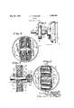
- Fig. 1 is a fragmentary view'in elevation showing the improved clutch arranged to connect the rotor shaft of an electric motor to a shaft to be driventherefrom;
- Fig. 2 is a view partly in Aelevation and partly in section taken on the line 2 2 of Fig. 1, on an enlarged scale; f
- Fig. 3 is a View principally in sect-ion taken onthe line 3-3 ofFig. l2;
- Fig. 4 is a viewy correspondingpto Figp?) but showing a different type of weight in the shoes. d A
- the numeral 5 indicates an electric motor and the numeral 6 indicatesa shaftv axially aligned with the rotor shaft of said motor.
- a flexible coupling 12, ofwell-known 4commercial' formh connects the rotor shaft of the motor ⁇ tothe 4,shaft 6.
- Thiscoupling 12 includes a fibre disk l'having on each vface a diametrically extended tongue 14 andthe two tongues 14 extend at right angles to each other.
- Onepof the tongues :14 loosely vextends into a groove in the outer endof a hub 15 rigidly secured by a set-screw tothe outer end'of the rotor shaft of the Vmotor 5 and the other tongue 14v loosely extends into a groove in the outer end of the hub 9.j
- ⁇ Cast on theinner face of theV clutch member 7 is a vpair of parallel perpendicular flanges 16 which are laterally spacedto form, together with said clutch member, a diametrically extended channeled way or shoe guide 17 the ends of which terminate substantially 17 at diametrically opposite points from the shaft 6.
- Each shoe 18 is in theform of a block, theouter end of which'is on acurve having the sameradiusas the internal sur- 't face of the drum 8 ⁇ for frictional contact therewith ⁇ throughout the entire area thereof.
- the inner ends .of the shoes 18 are notched to afford vclearance for the shaft' and permit the required radial movements of said shoesin the way 17;
- the drum 8 is preferably mademfrom cast 'the shoes 18 is such that they: freely move in f thevwayr17 and betweenthefclutch member v at the periphery of said member.
- the weights 19 are embedded inthe shoes 18 so that they dol not come in contact with either the. clutch member 7, drum 8- or the flanges 16. l
- Figs. 2 and 3 show each shoe 18provrided with two weights 19 cach'of which is in the f formi cfa round metalrbar mounted in a borelike cavity 20 which entends into said shoe from one edge thereof, and is securely held therein by friction or otherwise.
- Weights 19 are. of the same weight and their positions in the shoes 18--are exactly the same so that the action of said shoes on the drum 8, at diametrically opposite points under'the action'of centrifugalforce, is the same; or, inJ other words, these equally balanced shoes ⁇ 18L move at the same rate of speed and' force during the setting and. re-
- each shoe 1-8 is laterally spaced' radially fromthe aX-is of the shaft 6 and their axes are in the plane ofrotation of the clutch andl at right angles to the direction of travelY of said' shoesin the way 17.
- Fig. 4 shows a' structure identical with that shown' in Figsizl, 21 and 3y and ythelparts thereof havethesame reference characters except as tothe weights which are designated by the numeral V20;
- the weights 20,. shown in Fig. 4, are variable and shiftable in the shoes 18.
- These weights 20 eachy include a body madeV up of a multiplicity ofV shot loosely held confined in a cavityr- 21 formed inthe respective shoef18 and closed by a stopper 22 ⁇ preferably of the same materialV as the shoe.
- the shiftableweights 2() move outwardin the cavities ⁇ 21 underL centrifugal force lduring the rotation ofthe clutch ⁇ member17 by the rotor shaft of the motor 5 and tightly press the shoes 18 against the drum 8.y
- These weights 20 may be varied, at will, by removing part of the shot or adding other shot thereto. By forming the weights 20 each from the same number of shot, said weights will be equally balanced.
- Thel two cavities 21in each shoe 18 have'their axes spaced equidistances from the centers of said shoe both as to thickness and width thereof.
- therclutch is ⁇ de-l signedy to permit thev motor to build upa i speed and then pick upzthe load ⁇ gradually,
- a clutch comprising a driving member and a driven member, onek of Which is a drum and the other of which is provided vvitha single channeled shoe into the drum and substantially the full diameter thereof, and a pair of loose shoes loosely held by the guide for contact with the drum at diametrically opposite points and subject to centrifugal forceduring rotation of the respective member.
- a clutch comprising a driving member and a driven member, one of which is a drum and the other of Which is provided With a shoe guide extending into the drum, a loose shoe loosely held by the guide Vfor contact with the drum and subject to centrifugal Vforce during rotation of the respective member, and a cylindrical Weight in the shoe which extends radially thereof.
- a clutch comprising a driving member and a driven member, one of which is a drum and the other of Which is provided with a shoe guide extending into the drum, a loose shoe loosely held by the guide for contact with the drum and subject to centrifugal force during rotation of the respective member, and a pair of Weights inthe shoe laterally spaced eircumferentially of the drum and positioned equal distances from the transverse center of the shoe.
- a clutch comprising a driving member and a driven member, one of Which is a drum and the other of which is provided With a shoe guide extending into the drum, a" loose block-like shoe loosely held by the guide for a shiftable Weight in each chamber subjectv kto centrifugal force during rotation of the guide Which extends chamber subject lto centrifugal force during rotation of the respective member.
- a clutch comprising a driving member and aT driven member, one of which is a drum and the other of ⁇ which; is provided With a ⁇ shoe guide extending into the drum, a loose j shoe loosely held by theguide for contact with the drum and subject .to ⁇ centrifugal* force during rotation of the' respective mem ber, said shoe having tvvo closed internal chambers laterally spaced circumferentially of the drum and positioned equal distances from the transverse center of the shoe, and
- a clutch comprising a driving member and a driven member, one of which is a drum and the other of Which is vprovided With 'a pair of laterally spaced parallel flanges arranged to form a single radial shoe guide Which extends into the drum and substantiallyl the full diameter thereof, and a 'pairof loose block-like shoes loosely ⁇ held by v.the guide for contact with the drum at diametrically opposite points and subject to 4fcenl trifugal force lduring rotation of. the respective member.
- a clutch comprising a driving member and a driven member, one of which 1s a drum and the other of which is a disk forming one of the heads of the drum, each of said members having an external hub for securing the 100 same to a shaft, said diskV having on its inner face a pair of laterally spaced parallel flanges arranged to form a single radial shoe guide which extends into the drum and substantially the full diameter thereof, and a pair i of loose block-like shoes loosely held by the contact With the drum and subject to cen-l trifugal force during rotation Vof the Vrespective member, said shoe having a closed internal cylindrical chamber which extends radi- ⁇ ally thereof, and a shiftable Weight in the so Y
Landscapes
- One-Way And Automatic Clutches, And Combinations Of Different Clutches (AREA)
Description
Patented May 24, 19.32-
UNITED STATES .PATENT oFFcE LEROY T. rUTsoHER, or MINNEAPoLIs, MINNEsOTA, AssIGNon To EDWIN n. BENMAN, Y OF MINNEAPOLIS, MINNESOTA f f CLUTCH Application led October 1, 1930,v Serial No. 485,670.l
My invention has for its object the provision ofan extremely simple and highly eficient centrifugal force friction clutch and,
to this end,`it consists of the novel construction and arrangement of parts thereinafter described and defined in the claims.
This improved clutch, while intended for general use, is especially well adapted as a` driving Connection between an electric motor and positive operatlng connections for opening and closing garage-doors and the like,-where the action'of the load is stiff and l difficult to start due to the weightl thereof and in such cases the clutch will permit the l .15 Ymotor to build up a speed and gradually pick up the load. This action of the clutch permits the motor to overcome its static fricl tion and the inertia of the load with a smooth action.
The invention further provides a clutch that is so evenly balanced in its action as to make the same especially well adapted for usein the operating connections formechanism wherein, it is essential that vibration,
26 produced by setting and releasing the clutch, is reduced to a'minimum. v
In the accompanying drawings, whichillustrate the invention,` like characters indicate like parts throughout the several views.
Referring to the drawings:
Fig. 1 is a fragmentary view'in elevation showing the improved clutch arranged to connect the rotor shaft of an electric motor to a shaft to be driventherefrom;
Fig. 2 is a view partly in Aelevation and partly in section taken on the line 2 2 of Fig. 1, on an enlarged scale; f
Fig. 3is a View principally in sect-ion taken onthe line 3-3 ofFig. l2; and
Fig. 4 is a viewy correspondingpto Figp?) but showing a different type of weight in the shoes. d A
The numeral 5 indicates an electric motor and the numeral 6 indicatesa shaftv axially aligned with the rotor shaft of said motor.
The improved clutch vcomprisesa driving member in the form of a disk 7 and a driven member 8 1n the form offa -drum havmg'an annular internal shoe-'engaging surface.
Formed lwiththe outer, face of the clutch y member 7`V is an outwardly projecting hub 9 and formedfon theouter face of the back of Y ,the drum-8 is a hub 10. :Bothhclutchmem- `hers 7 and 8 are mounted on the shaft 6 which holds the same inV true axialalignment rand against angular 'or wobble movement in Y respect to each other. TheV clutchV member 7 1s loose on the shaft Gand the drum 8 is rigidly secured thereto by a set-screw 11 that "has.'threadedfengagement with'the Vhub 10 and impingesagainst said shaft, see Fig-.3.
y A flexible coupling 12, ofwell-known 4commercial' formh connects the rotor shaft of the motor` tothe 4,shaft 6. Thiscoupling 12 includes a fibre disk l'having on each vface a diametrically extended tongue 14 andthe two tongues 14 extend at right angles to each other. Onepof the tongues :14 loosely vextends into a groove in the outer endof a hub 15 rigidly secured bya set-screw tothe outer end'of the rotor shaft of the Vmotor 5 and the other tongue 14v loosely extends into a groove in the outer end of the hub 9.j
`Cast on theinner face of theV clutch member 7 is a vpair of parallel perpendicular flanges 16 which are laterally spacedto form, together with said clutch member, a diametrically extended channeled way or shoe guide 17 the ends of which terminate substantially 17 at diametrically opposite points from the shaft 6. Each shoe 18 is in theform of a block, theouter end of which'is on acurve having the sameradiusas the internal sur- 't face of the drum 8` for frictional contact therewith `throughout the entire area thereof. The inner ends .of the shoes 18 are notched to afford vclearance for the shaft' and permit the required radial movements of said shoesin the way 17;
The drum 8 is preferably mademfrom cast 'the shoes 18 is such that they: freely move in f thevwayr17 and betweenthefclutch member v at the periphery of said member. A pairof 50 A i loose` shoes ,18'are'loosely mounted 'in the way 7 and the back of the clutch member8 but at the same time, are held thereby against such Y angular movements in respect thereto that tional contact with the drumv 8. shown,
the weights 19 are embedded inthe shoes 18 so that they dol not come in contact with either the. clutch member 7, drum 8- or the flanges 16. l
Figs. 2 and 3 show each shoe 18provrided with two weights 19 cach'of which is in the f formi cfa round metalrbar mounted in a borelike cavity 20 which entends into said shoe from one edge thereof, and is securely held therein by friction or otherwise. The
leasing of the clutch, .and hence, prevent vi brations in the clutch that'would` otherwise be producedk byfthe'acontact 'of thehshoesy 18 with the vdrum. 8 andv thereleasing of the same therefromy at different times and: under unequal pressure. Furthermore, by holding` thefclutchk members 7 and 8 in true axial alignment, which is' accomplished as shown by mounting said' members on the same shaft,
lmaterially assists the equally balanced shoes 18V in accomplishing the result desired. The Weights 19 in each shoe 1-8 are laterally spaced' radially fromthe aX-is of the shaft 6 and their axes are in the plane ofrotation of the clutch andl at right angles to the direction of travelY of said' shoesin the way 17.
Fig. 4 shows a' structure identical with that shown' in Figsizl, 21 and 3y and ythelparts thereof havethesame reference characters except as tothe weights which are designated by the numeral V20; The weights 20,. shown in Fig. 4, are variable and shiftable in the shoes 18. These weights 20 eachy include a body madeV up of a multiplicity ofV shot loosely held confined in a cavityr- 21 formed inthe respective shoef18 and closed by a stopper 22 `preferably of the same materialV as the shoe.
The shiftableweights 2() move outwardin the cavities` 21 underL centrifugal force lduring the rotation ofthe clutch`member17 by the rotor shaft of the motor 5 and tightly press the shoes 18 against the drum 8.y These weights 20 may be varied, at will, by removing part of the shot or adding other shot thereto. By forming the weights 20 each from the same number of shot, said weights will be equally balanced. Thel two cavities 21in each shoe 18 have'their axes spaced equidistances from the centers of said shoe both as to thickness and width thereof.
Operation ofclatch Under normal conditions the impro-ved clutch will carry a load up to the speed of themotor in the same manner as an ordinary direct connected drive.
However, in case the loadis, stiff: or difficult to'start due tofweight, therclutch is` de-l signedy to permit thev motor to build upa i speed and then pick upzthe load` gradually,
and as previously state-d, this tends first,to overcome the static frictionofthe. motor and' thereafter,.when the speedof. the motor" has been built up, overcome the inertia lofthe load with aV result that the load. is'easily started with asmooth action. y Y A very important feature is thatit tends-to keepthe starting current of the motor down so that Vthere is nofexcessive starting current on a heavy' loadvwhich protects the motor and permits the proper, fusing` thereof. i
The action of the clutch The driving clutch member 7 being'fast on the rotor shaftrof the motor 5 is free to.
turn `within the drum 8 when the motor 5 vis at rest or,xwhen turned by hand power is transmitted from the drivingy member through the shoes 18 to the drum 8. When the current is applied to the motor5 the clutch member 7 .and shoes 18 rotate within the drum 8 for lan instant before the speed reaches a Vpoint atY which theshoes18engage of. this iut-Ch" .ion
the' drum 8. As the speed of the motor 5 increases, whichr ity does very quickly, the cen-v trifugal force of the shoes18 overcomes the restraining force of the load. If the load can be started readily the speed continues tofincrease until. a maximum speed'. and centrifu gal force ofthe clutchis in action.
son and requires high initial torque to set it in motion the actionv is different. In this case, since the characteristic lof the loadprevents the drumfrom turning freely, the-fric- -tionV betweenthe shoes 18 and. the d'rum8` slows the motor down to a speed lat which the centrifugalforce of the shoes 18 is overcome and. allows the clutch/to slipor release. The motor 5 then comes up to speed. again and theshoes 18r engage the `drum 8.` This However, if the load is stiff for some reaaction takes place very rapidly and since the shoes 18 come in contact with thel drum 8 very quickly a highv torque is transmitted tothe load. rllhe intensity of this action iss.
increased until the heat generated by the friction of the shoes 18 on the drum 8 increases a coefficient of friction by said shoes and drum to a point Where the entire kinetic energy of the motor 5 is transmitted to the load. The result is a starting torque many times greater than full load torque suiicient to start even the most obstinate load.
On a heavy load the action continues until the load is started or until the load overcomes the centrifugal force and holding power of the clutch, Without damaging the clutch or equipment.
What I claim is:
l. A clutch comprising a driving member and a driven member, onek of Which is a drum and the other of which is provided vvitha single channeled shoe into the drum and substantially the full diameter thereof, and a pair of loose shoes loosely held by the guide for contact with the drum at diametrically opposite points and subject to centrifugal forceduring rotation of the respective member.
2. The structure defined in claim 1 in which the shoe is block-like and its Width is slightly less than that of the guide.
3. A clutch comprising a driving member and a driven member, one of which is a drum and the other of Which is provided With a shoe guide extending into the drum, a loose shoe loosely held by the guide Vfor contact with the drum and subject to centrifugal Vforce during rotation of the respective member, and a cylindrical Weight in the shoe which extends radially thereof.
4l. The structure defined in claim 3 in` short of the outer end of the shoe and isy covered thereby.
5. A clutch comprising a driving member and a driven member, one of which is a drum and the other of Which is provided with a shoe guide extending into the drum, a loose shoe loosely held by the guide for contact with the drum and subject to centrifugal force during rotation of the respective member, and a pair of Weights inthe shoe laterally spaced eircumferentially of the drum and positioned equal distances from the transverse center of the shoe.
6. The structure delined in claim 5 in Which the Weights are independently variable.
7 A clutch comprising a driving member and a driven member, one of Which is a drum and the other of which is provided With a shoe guide extending into the drum, a" loose block-like shoe loosely held by the guide for a shiftable Weight in each chamber subjectv kto centrifugal force during rotation of the guide Which extends chamber subject lto centrifugal force during rotation of the respective member. p
8. A clutch comprising a driving member and aT driven member, one of which is a drum and the other of` which; is provided With a` shoe guide extending into the drum, a loose j shoe loosely held by theguide for contact with the drum and subject .to `centrifugal* force during rotation of the' respective mem ber, said shoe having tvvo closed internal chambers laterally spaced circumferentially of the drum and positioned equal distances from the transverse center of the shoe, and
respective member.
9. The structure defined in claimV 8 -in Which each Weight is' individually variable.`
lO. A clutch comprising a driving member and a driven member, one of which is a drum and the other of Which is vprovided With 'a pair of laterally spaced parallel flanges arranged to form a single radial shoe guide Which extends into the drum and substantiallyl the full diameter thereof, and a 'pairof loose block-like shoes loosely` held by v.the guide for contact with the drum at diametrically opposite points and subject to 4fcenl trifugal force lduring rotation of. the respective member. Y Y
ll. A clutch comprising a driving member and a driven member, one of which 1s a drum and the other of which is a disk forming one of the heads of the drum, each of said members having an external hub for securing the 100 same to a shaft, said diskV having on its inner face a pair of laterally spaced parallel flanges arranged to form a single radial shoe guide which extends into the drum and substantially the full diameter thereof, and a pair i of loose block-like shoes loosely held by the contact With the drum and subject to cen-l trifugal force during rotation Vof the Vrespective member, said shoe having a closed internal cylindrical chamber which extends radi-` ally thereof, and a shiftable Weight in the so Y
Priority Applications (1)
| Application Number | Priority Date | Filing Date | Title |
|---|---|---|---|
| US485670A US1859963A (en) | 1930-10-01 | 1930-10-01 | Clutch |
Applications Claiming Priority (1)
| Application Number | Priority Date | Filing Date | Title |
|---|---|---|---|
| US485670A US1859963A (en) | 1930-10-01 | 1930-10-01 | Clutch |
Publications (1)
| Publication Number | Publication Date |
|---|---|
| US1859963A true US1859963A (en) | 1932-05-24 |
Family
ID=23929014
Family Applications (1)
| Application Number | Title | Priority Date | Filing Date |
|---|---|---|---|
| US485670A Expired - Lifetime US1859963A (en) | 1930-10-01 | 1930-10-01 | Clutch |
Country Status (1)
| Country | Link |
|---|---|
| US (1) | US1859963A (en) |
Cited By (7)
| Publication number | Priority date | Publication date | Assignee | Title |
|---|---|---|---|---|
| US2543873A (en) * | 1947-03-20 | 1951-03-06 | John E Scruby | Centrifugal clutch |
| US2718294A (en) * | 1951-07-27 | 1955-09-20 | Fairbanks Morse & Co | Automatic, centrifugal clutch mechanisms |
| US2910160A (en) * | 1955-11-12 | 1959-10-27 | Meder Max | Centrifugal force coupling |
| US3026055A (en) * | 1958-02-21 | 1962-03-20 | American Enka Corp | Clutch for thread collecting machines |
| US3190422A (en) * | 1961-04-07 | 1965-06-22 | Daimler Benz Ag | Centrifugal clutch with vibration damper |
| US3687254A (en) * | 1970-09-16 | 1972-08-29 | Roy H Bystrom | Centrifugal clutch |
| US20080156609A1 (en) * | 2007-01-03 | 2008-07-03 | The Hilliard Corp. | Tunable centrifugal clutch |
-
1930
- 1930-10-01 US US485670A patent/US1859963A/en not_active Expired - Lifetime
Cited By (8)
| Publication number | Priority date | Publication date | Assignee | Title |
|---|---|---|---|---|
| US2543873A (en) * | 1947-03-20 | 1951-03-06 | John E Scruby | Centrifugal clutch |
| US2718294A (en) * | 1951-07-27 | 1955-09-20 | Fairbanks Morse & Co | Automatic, centrifugal clutch mechanisms |
| US2910160A (en) * | 1955-11-12 | 1959-10-27 | Meder Max | Centrifugal force coupling |
| US3026055A (en) * | 1958-02-21 | 1962-03-20 | American Enka Corp | Clutch for thread collecting machines |
| US3190422A (en) * | 1961-04-07 | 1965-06-22 | Daimler Benz Ag | Centrifugal clutch with vibration damper |
| US3687254A (en) * | 1970-09-16 | 1972-08-29 | Roy H Bystrom | Centrifugal clutch |
| US20080156609A1 (en) * | 2007-01-03 | 2008-07-03 | The Hilliard Corp. | Tunable centrifugal clutch |
| US7717250B2 (en) * | 2007-01-03 | 2010-05-18 | The Hilliard Corporation | Tunable centrifugal clutch |
Similar Documents
| Publication | Publication Date | Title |
|---|---|---|
| US1618644A (en) | Centrifugal clutch | |
| US1805692A (en) | Automatic slip coupling | |
| CN105992886B (en) | Drive for a dog clutch and method of controlling the drive | |
| US2000713A (en) | Clutch | |
| US1859963A (en) | Clutch | |
| US10830289B2 (en) | Electromagnetic clutch of a brushless control-by-wire centrifugal ball arm engagement device | |
| US3028737A (en) | Couple | |
| US834499A (en) | Clutch device. | |
| US2471747A (en) | Centrifugally operable clutch | |
| US2626033A (en) | Centrifugal servo clutch | |
| US2753031A (en) | Centrifugally responsive couplings | |
| US1859334A (en) | Centrifugal clutch | |
| US2166961A (en) | Torque transmitting device | |
| US2386071A (en) | Clutch construction | |
| US1801590A (en) | Clutch and operating device | |
| US1849177A (en) | Automatic operating device for clutches | |
| US2397869A (en) | Driving mechanism | |
| US3833101A (en) | Typewriter motor clutch | |
| US2485211A (en) | Time delay centrifugal clutch | |
| JPS5913129A (en) | Dry type multiple-disc clutch | |
| US1817542A (en) | Centrifugal clutch | |
| US1261594A (en) | Dynamo-electric clutch. | |
| SU632849A1 (en) | Centrifugal friction clutch | |
| US2745975A (en) | Centrifugally controlled magnetic couplings | |
| US2089870A (en) | Automatic clutch |